MDI window
Locations:
Project Tree > CNC Machine Branch Right Mouse Shortcut Menu > MDI
Project tab >  (MDI)
(MDI)
Toolbar short cut: ![]()
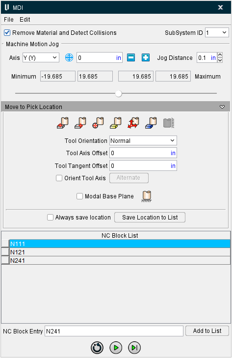
The features on the MDI window enable you to manually enter and process blocks of G-Code data. The MDI, or "Manual Data Input" function provides a quick and easy way of verifying that the machine/control combination responds to G-Code data commands as expected.
Menu Bar

File Menu
The features in the File menu enable you to import, export or print NC blocks created in the NC Blocks table.
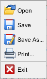
Open — Opens a file selection window enabling you to specify a text, or .mcd, file to populate the NC Blocks table.
Save — Saves (updates) an existing text (.mcd) file with the current NC blocks.
Save As — Opens a window enabling you to save the contents of the NC Blocks table to a new file.
Print — Opens a window enabling you to print the NC Blocks table.
Exit — Closes the MDI window.
Edit Menu
The features in the Edit menu enable you to manipulate blocks in the NC Block table.
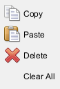
Copy — Use to copy the highlighted block(s) in the NC Block table to the Windows clipboard.
Paste — Use to paste a copied block(s) after the highlighted block in the NC Block table.
Delete — Use to delete the highlighted block(s) from the NC Block table
Clear All — Use to clear all blocks from the NC Block table.
Main Window
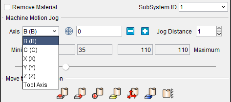
Remove Material and Detect Collisions — Use to activate/de-activate Vericut material removal.
When toggled "Off" (no check):
-
Material removal is not done
-
Neither Machine nor project collision checking is done
-
No over-travel limit checking is done.
When toggled "On" (check), all of the above will be performed.
SubSystem ID — Use this feature to specify which machine subsystem the G-Code data command is to be applied to.
Machine Motion Jog
The Machine Motion Jog features enable you to incrementally jog the position of the Vericut machine in the same way that you can jog the real machine.
Axis — Indicates the current axis that the "Jog" feature will apply to. To change the current axis, simply select it from the pull-down list. The Axis list includes all of a machine’s moving axes as well as the Tool Axis. The name used for a particular Machine axis will be shown in parentheses as shown in the example below:
![]() (Machine CSYS) /
(Machine CSYS) / ![]() (Local CSYS) — This icon toggles between machine coordinate system and local coordinate system enabling you to specify the coordinate system that you want the Jog motion to be relative to. Left click on the icon to switch between modes.
(Local CSYS) — This icon toggles between machine coordinate system and local coordinate system enabling you to specify the coordinate system that you want the Jog motion to be relative to. Left click on the icon to switch between modes.
When in local coordinate system mode, it is assumed that the axis motion follows the format of “Axis + Position”. For example, if current axis is the “U” axis and its position is “10mm”, then the motion command is “U10”. If your control uses a different format than described above, an undesirable simulation will occur.
When in machine coordinate system mode, jog motion bypasses the control, so the local coordinate is not updated. When you switch from machine coordinate system mode to local coordinate system mode while jogging, the previous “local” position in the control will be used, which does not reflect the current local position.
The current axis position (linear or rotary), with respect to the Axis "zero" position, is displayed in text field next to Axis.
Use the ![]() (increase) and
(increase) and ![]() (decrease) buttons to jog the machine the specified "Jog Distance" each time you press them. You can also press and hold the button down to repeatedly move the specified distance.
(decrease) buttons to jog the machine the specified "Jog Distance" each time you press them. You can also press and hold the button down to repeatedly move the specified distance.
Jog Distance — Use to set the distance the axis position will move by a single click on increase/decrease buttons.
📝 NOTE: Moving the machine axes with Machine Motion Jog will not produce a block in the NC Blocks table until the Save Location as NC Block button is pressed.
Machine Travel Limits Slider
The Machine Travel Limits Slider enables you to move a specified machine axis through the entire range of travel. As you move the slider in the MDI window, you will see the specified axis moving in a Machine view in the graphics area. Collisions will be displayed in the graphics area. Collision and other error messages will be displayed in the Logger.
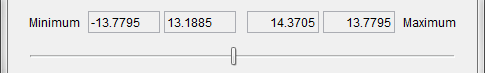
The numbers in the four boxes, from left to right, represent the following:
-
The value of the Minimum Travel Limit
-
The distance between the Minimum Travel Limit and the current axis position.
-
The distance between the Maximum Travel Limit and current axis position.
-
The value of that Maximum Travel Limit.
The Minimum and Maximum Travel Limit values are automatically set for the selected axis based on the travel limit settings on the Machine Settings window: Travel Limits tab.
The axis that you want to move is specified using the Axis feature describe above in the Machine Motion Jog section.
Use the slider to move the specified axis. You can click on the slider and drag it to the left (toward the Minimum travel limit) or to the right (toward the Maximum travel limit). You can also click on the slide bar to the left (toward the Minimum travel limit) of the slider or click on the slide bar to the right (toward the Maximum travel limit) of the slider. Each time that you click on the slide bar, the slider will move approximately 10% of the total distance between the travel limits in the selected direction.
The slider will become disabled in the following situations:
-
The travel limit specified for the axis on the Machine Settings window: Travel Limits tab is invalid or does not exist
-
Travel limit record, on the Machine Settings window: Travel Limits tab, for the specified axis has the Ignore option is toggled “on” (checked).
-
The specified axis is the Tool Axis.
In each situation, the row above the slider (with the four boxes) will be replaced with a message explaining the reason why the slider is disabled.
Move to Pick Location
The Move to Pick Location features enable you to position a tool component at a specific point by picking on stock, or machine models and components, displayed in the Vericut Graphics Area.
![]() Pick Point — enables you to position the tool at any point in a Workpiece or Machine view. Vericut will use the selected point and a vector normal to the surface of model or stock at the selected point. Moving the cursor in the view over model will display the point and vector associated with the current position. Click the left mouse button to select the point.
Pick Point — enables you to position the tool at any point in a Workpiece or Machine view. Vericut will use the selected point and a vector normal to the surface of model or stock at the selected point. Moving the cursor in the view over model will display the point and vector associated with the current position. Click the left mouse button to select the point.
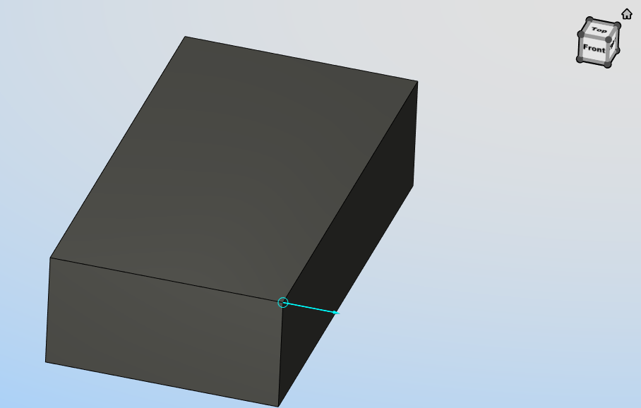
 Pick Vertex — enables you to easily position a tool on one of the six key points associated with the triangles representing the faces of an uncut model (machine, fixture components or stock model before cutting). For each triangle, the points consist of the three vertices and the midpoint of each of the triangle's three sides. Vericut selects the point closest to your mouse pick. Moving the cursor in the view over model will display the nearest triangle side and point. Click the left mouse button to select the point. Vericut will use the selected point and a vector normal to the surface of model or stock at the selected point. If the mouse pick is over the cut stock, Pick Vertex works in the same way as the Pick Point feature described above.
Pick Vertex Example
 Pick Circle — enables you to position a tool at a point along the axis of a cylinder. This feature requires two picks. The first pick designates the plane that the point is to be in. The second pick is the cylindrical feature whose axis the point lies along. Vericut will use the point where the axis of the cylindrical feature intersects the plane. The associated vector is defined by the cylindrical axis.
 Pick Model Origin — enables you to position the tool at a point represented by the origin of a model's coordinate system. The vector is defined as the model coordinate system's Z-axis. Placing the cursor over any model will display the model's coordinate system. Select the model using the left mouse button.
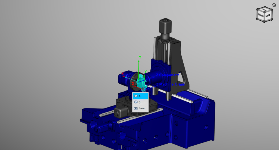
 Pick CSYS Origin — enables you to position a tool at a point represented by the origin of any displayed coordinate system. Vericut uses the coordinate system axis closest to the pick point as the vector. Move the cursor near one of the coordinate system's axis and an arrow representing the vector will display along the axis. Click with the left mouse button select the origin point and vector.
Pick CSYS Origin Example
Notice the directional arrow overlaps the Y-axis of the CSYS indicating that it will be used as the vector.
 Pick Component Origin — enables you to position the tool at a point represented by the origin of a component's coordinate system. The vector is defined as the component coordinate system's Z-axis. Placing the cursor over any component will display the component's coordinate system. Select the component using the left mouse button.
![]() Pick Next Side Plane — when active, this feature enables you to select a plane to position the side of the tool to. Activate "Pick Next Side Plane" mode by:
Pick Next Side Plane — when active, this feature enables you to select a plane to position the side of the tool to. Activate "Pick Next Side Plane" mode by:
-
Use the Pick Base Plane feature, described below, to select a base plane.
-
Toggle Modal Base Plane, described below, "On".
- Set Tool Orientation, described below, to Tangent.
- Position the tool using any of the above methods. At this point the Pick Next Side Plane icon should be active.
📝 NOTE: The order in which these steps are carried out is important.
After completing the above steps, the tool is positioned tangent to the surface at the pick point. This tangent plane can be driven along for the next motion if the next pick is in "Pick Next Side Plane" mode. After the motion to the "next side plane" is completed, the previous "side plane" is replaced by current "next side plane" and tool is ready to be driven to the next "Pick Next Side Plane" location. You can continue driving the tool along in this manner as long as you continue selecting "Pick Next Side Plane" locations.
Tool Orientation — Use to specify the tool vector orientation in relation to the picked vector (using any of 6 methods specified above). Choose either Normal or Tangent. Normal specifies that tool vector is set to the pick vector value. Tangent specifies that tool vector will be aligned tangent to the plane created by crossing last tool vector and pick vector. The tool position will be offset by maximum tool radius from the plane. Using a Tangent orientation with the Pick Point method will position the tool tangent to a wall by using one mouse click on the wall. Tool Tangent Offset can be applied in addition to tool radius offset.
Tool Axis Offset — Use to specify a value representing a distance offset the tool along the tool axis vector. A positive value moves up the tool axis from the tool pick point. A negative value moves down the tool axis from the pick point.
Tool Tangent Offset — Use to specify a value representing an offset of the tool in radial direction (perpendicular to the tool axis), in addition to tool radius, when Tangent tool orientation is active. This offset can be used to prevent scratching a part when positioning tool tangent to wall (positive value), or for cutting a wall (negative value).
Orient Tool Axis — Use to change tool axis orientation. When the box is checked and machine has 5 axis capabilities, the tool axis will be set based on pick vector value and Tool Orientation method. If the box is not checked, the tool axis vector remains unchanged while changing to the position to pick point.
Alternate — Use this button to orient the tool using alternative rotary axes solution. When tool axis vector is resolved on a pick, the shortest route for rotary axes is applied. To find what the alternative solution is, use this button. This button is active only after a change to the tool axis vector. Subsequent use of this button toggles from one possible solution, to another.
Modal Base Plane — Use this check box to specify a modal base plane is to be used as the reference for Tool Axis Offset. If box is checked, tool positions for all pick generated motions are offset relative to the specified modal base plane. Use Pick Base Plane, described below, to select the plane. If the box is unchecked, tool positions for all pick generated motions are offset relative to current pick point.
 Pick Base Plane — Use to select a modal base plane (see above) to establish a common base for Tool Axis Offset. This icon is in same group with other Move to Pick Location icons (deactivates the others when pressed) but it is a one shot pick (becomes inactive after each successful pick).
Always Save Location — Use this feature to simplify NC block generation. When the check box is checked, an NC block is created in NC Block Entry text field for every resolved pick location and is saved in NC Blocks List. If the box is not checked, you must use the Save Location to List button, at each pick location, to create an NC block and store it in NC Block List. This feature is not applicable when Machine Motion Jog is being used since a single jog does not create any NC Block information to save.
Save Location to List — Use to create an NC block from the current pick location and saves it in NC Block List.
📝 NOTE: The Save Location to List button does not execute the block in NC Block Entry text field. It simply creates the NC block and stores it in the NC Block List.
In Machine Motion Jog mode, it is important to create NC blocks for each desired machine position before jogging the machine to the next location. In this case, after using Save Location to List to create the block and store it in the NC Block List, make sure that the newly added block is highlighted and then press Play Selected NC Blocks to process the NC block and update the control with the machine component's current location.
In Move to Pick Location mode, the machine moves to the pick location (at the mouse click) and this location is processed through the control, and all other possible translations, before actual machine axes are defined and positioned.
NC Blocks List — the list contains a sequence of NC blocks that have been created. The list enables you to select a block, or sequence of blocks, in order to delete, copy and paste, or execute the selected block(s). A right mouse click displays a pop-up menu with features that enable you to edit, or execute, blocks in the list. Edit the content of a block by double clicking on the block to put it in "edit" mode, then make the necessary changes.
↘️ Shortcut: Right-click in the NC Block List to display the following menu:
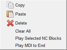
📝 NOTE: Copy, Paste, Delete, and Clear All are described in the Edit Menu section above. Play Selected NC Blocks and Play MDI to End are described below.
Manipulating blocks in the in the NC Block List:
-
Use the "Shift" key to select a consecutive range of blocks. Click on the first block in the range so that it becomes highlighted, and then while holding down the "Shift" key, click on the last block in the range. All of the blocks between the first and last should now be highlighted.
-
Use the "Ctrl" key to select multiple individual blocks. Click on the first block so that it becomes highlighted, and then while holding down the "Ctrl" key, select additional blocks. Each block will become highlighted when it is selected.
- Re-order blocks in the NC Block List by left-clicking on the square button at the beginning of the row and drag the row (while keeping the left mouse button depressed) to the desired position.
NC Block Entry — is a text buffer where an internally generated NC block is displayed, or an NC block can manually be entered. Use the Add to List button to add the block displayed in the NC Block Entry text field to the NC Block List.
Add to List — Use to add the contents of the NC Block Entry text field to the NC Block List.
 (Reset Model and MDI) — Resets the Vericut model in the graphics area and highlights the first block in the NC Block List.
 (Single MDI Step) — Use this icon to execute a single NC block, or a selected sequence of blocks, in NC Block List.
When an NC block in the MDI window calls a subroutine like the M06 command in the example below, three additional icons are displayed as shown.

In addition, a message is displayed below the logger explaining the presence of the three additional icons.
The additional icons (MDI Step Controls) enable you to specify what you want Vericut to do with the subroutine that is being called. You can choose to "step into" the subroutine, "step over" the subroutine, or "step out" of the subroutine if you have already stepped into it.
The function of the three MDI Step Control icons is identical to the Subroutine Option icons that display when you right-click on the (Step / Subroutine Options) icon in the main Vericut window. The three MDI Step Control icons are described below:
 (Step Into Subroutine) — When you come to a subroutine, step into the subroutine, and continue stepping.
 (Step Over Subroutine) — When you come to a subroutine, do not step into it, execute the subroutine, and continue stepping on the next line of the calling program.
 (Step to End of Subroutine) — If you are inside a subroutine, finish executing the current subroutine, and continue stepping on the next line of the calling routine.
Tip: Position the cursor over the icon and a tip appears to remind you of each icon’s function.
 (Play MDI to End) — Use this icon to execute all blocks in the NC Block List
See Manually Moving the Machine via MDI in the Using the MDI window section of Vericut Help for additional information.
📝 NOTES:
-
Use of Machine Motion Jog and Play MDI to End require a Machine Simulation license.
-
Do not attempt to use MDI before machine construction is complete. If the Stock, Tool, and all motion components are not present in the machine definition, the machine may not respond to motion commands as expected.
- After adding motion type components to a machine, always press (Reset Model) before using MDI to test machine movements.
- Calls to subroutines and NC macros are not supported while in Move to Pick Location mode. Use a short test NC program file instead. Calls to subroutines and NC macros are supported while in Machine Motion Jog mode.
Using the MDI window
Manually Moving the Machine via MDI
After you define an NC machine and control, you can manually move the machine using commands typed in an "MDI console" window-similar to how an operator tests machine motions on the shop floor. This procedure can be especially helpful to test or prove-out newly constructed machines.
📝 NOTE: If you made any changes to the machine/control configuration, be sure to press (Reset Model) in the Vericut main window before manually moving the machine.
To manually enter and process a single block of machine code data:
-
Use one of the following methods to display the MDI window:
In the Project Tree, right click on a CNC Machine Branch and select MDI from the menu that displays.
OR Click on the(MDI) icon in the Vericut Toolbar.
OR Click on Project tab > MDI in the Vericut menu ribbon. -
In the MDI window, enter the block of data to in the NC Block Entry* text field at the bottom of the window.
- Press Add to List to add the block to the NC Block List.
- Press the (Play MDI to End) icon to process the data block. You can process as many blocks of data as you wish in this manner.
To use Machine Motion Jog
-
Use one of the following methods to display the MDI window:
In the Project Tree, right click on a CNC Machine Branch and select MDI from the menu that displays.
Click on the (MDI) icon in the Vericut Toolbar.
Click on Project tab > MDI in the Vericut menu ribbon. -
In the MDI window, select the machine axis that you want to jog, from the Axis pull-down list.
- Specify the distance that you want the machine to move each time you jog in the Jog Distance field.
- Use the
 (decrease) and
  (increase) buttons to jog the machine the specified "Jog Distance" each time you press them. You can also press and hold the button down to repeatedly move the specified distance.
Moving the machine axes with Machine Motion Jog will not produce a block in the NC Blocks List. Press the Save Location to List button to add the position to the NC Blocks List.
📝 NOTE: Using Machine Motion Jog requires a Machine Simulation license.
To use the Machine Travel Limits Slider
-
Use one of the following methods to display the Machine Settings window:
Click on the (Machine Settings) icon in the Vericut Toolbar.
Click on Machine/Control tab > Machine Settings in the Vericut menu ribbon. -
Click on the Travel Limits tab.
- Ensure that Minimum and Maximum travel limit values are specified for each of the machine’s axes.
-
Use one of the following methods to display the MDI window:
In the Project Tree, right click on a CNC Machine Branch and select MDI from the menu that displays.
Click on the(MDI) icon in the Vericut Toolbar.
Click on Project tab > MDI in the Vericut menu ribbon. -
In the MDI window, select the machine axis that you want to move, from the Axis pull-down list.
-
Use the Machine Travel Limits Slider to move the specified axis.
You can click on the slider and drag it to the left (toward the Minimum travel limit) or to the right (toward the Maximum travel limit).
You can also click on the slidebar to the left (toward the Minimum travel limit) of the slider or click on the slidebar to the right (toward the Maximum travel limit) of the slider. Each time that you click on the slidebar, the slider will move approximately 10% of the total distance between the travel limits in the selected direction. -
The axis motion will be displayed in a Machine view in the graphics area. Collisions will be displayed in the graphics area. Collision and other error messages will be displayed in the Logger.
📝 NOTE: Using Machine Motion Jog requires a Machine Simulation license.
To use graphic pick locations to create NC Blocks
-
Use one of the following methods to display the MDI window:
In the Project Tree, right click on a CNC Machine Branch and select MDI from the menu that displays.
Click on the(MDI) icon in the Vericut Toolbar. ,br>Click on Project tab > MDI in the Vericut menu ribbon. -
In the MDI window, click on the icon representing the Pick Location method that you want to use.
Tip: Hold the cursor over the icon to see what method that the icon represents. -
Pick a feature in the Vericut graphics area that is appropriate for the Pick Location method selected.
- Press the Save Location to List button to add the position to the NC Blocks List.
Tip: You can toggle Always save location "On" to automatically save each pick location as a block in the NC Block List.
To process one, or more blocks In the NC Block table:
-
Use one of the following methods to display the MDI window:
In the Project Tree, right click on a CNC Machine Branch and select MDI from the menu that displays.
Click on the(MDI) icon in the Vericut Toolbar.
Click on Project tab > MDI in the Vericut menu ribbon. -
In the MDI window, add blocks to the NC Block List using any of the methods described above.
To process a single NC block, or a selected sequence of blocks:
-
Select one or more blocks, in the NC Block List, so that they become highlighted.
-
Press
(Single MDI Step) process the highlighted blocks.
To process all blocks in the NC Block List:
Press the (Play MDI to End) icon to process all blocks in the NC Block List.
📝 NOTE: Using Play MDI to End requires a Machine Simulation license.
Press the (Reset Model and MDI) icon to reset the Vericut model in the graphics area and highlights the first block in the NC Block List.
To process a block in the NC Block List that calls a subroutine:
-
Use one of the following methods to display the MDI window:
In the Project Tree, right click on a CNC Machine Branch and select MDI from the menu that displays.
Click on the(MDI) icon in the Vericut Toolbar.
Click on Project tab > MDI in the Vericut menu ribbon. -
In the MDI window, add blocks to the NC Block List using any of the methods described above.
- When a block in the NC Block List calls a subroutine (for example a tool change command), the three additional icons will automatically display enabling you to specify how you want to handle the subroutine.
Press the (Step Into Subroutine) icon to step into the subroutine, and continue stepping through the blocks in the subroutine. You can see the blocks in the subroutine in the NC Program panel (Info tab > NC Program).
Once you have stepped into the subroutine, you can press the (Step to End of Subroutine) icon to finish executing the current subroutine, and continue stepping on the next line of the calling routine.
If you do not want to step though the subroutine, press the (Step Over Subroutine) icon to execute the subroutine and continue stepping on the next line of the calling program.
Tip: Position the cursor over the icon and a tip appears to remind you of each icon’s function.