Tool Use
Locations:
Info tab >  (Tool Use)
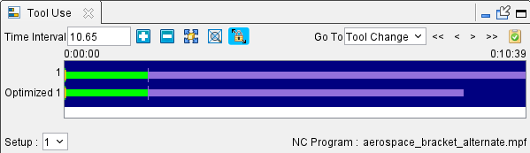
The Tool Use command button opens the Tool Use graph which shows the machining time, in minutes, spent by each simulated tool. The text displayed to the left of the graph line(s) is the sub-system ID. Each tool that cuts the part is shown in the graph with its cut color. Tool changes are indicated by a spike in the graph line. Positioning the mouse cursor on or above a graph line displays data about that tool.
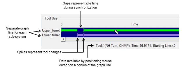
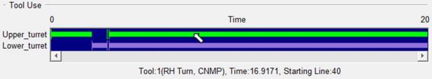
A 4-axis turned part has 2 graph lines; one for each turret. Machines with additional heads/sub-systems will have a graph line displayed for each. A gap in a graph line indicates idle time spent waiting for a turret/sub-system to synchronize. Positioning the mouse cursor above a gap in the graph displays the amount of idle time.
Zoom In/Out — Use the plus and minus buttons to zoom in or out respectively to better facilitate tool use viewing.
Fit — Use this button fit all of the results into the window.
Zoom in Box — Select this option to zoom in to a specific highlighted region that is designated by clicking within the display field. This function can also be accessed by holding down the right mouse button and then dragging a bounding box around the desired area.
Auto Zoom to Fit — Toggle this feature on (highlighted) automatically fit the tool use data in the viewing area. This feature is automatically toggled off (not highlighted) whenever the other zoom or fit features are used.
Go To — Use this dropdown menu and buttons to navigate to specific events in the Tool Use viewing area. Dropdown options include: Tool Change, Error, Warning, and NC Program. Button options include: Go To First, Go To Previous, Go To Next, and Go To Last.
NC Program Review — Use to active NC Program Review features.
There is also a Time display that shows how far into the simulation you are when the tool use occurs.
Tool Use graph features
Sample Tool Use graphs:
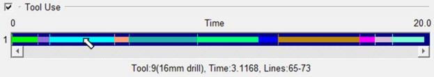
Tool Use graph from a milling NC Program:
Tool Use graph from 4-axis merged turning NC Program:
Tool Use Right Mouse Button Menu
Right-clicking in the Tool Use viewing area produces the following menu:
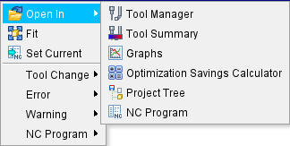
Open in — Generates a menu of options to view the selected tool. Options where to open include Tool Manager, Tool Use, Tool Summary, Optimization Savings Calculator, Project Tree, and NC Program.
Fit — Use this option fit all of the results into the window.
Set Current — Marks the currently highlighted portion of the Tool Use viewing area as the set option.
Tool Change — Use this menu to navigate between Tool Change sections. The expanded menu contains Go To First, Go To Previous, Go To Next, and Go To Last options.
Error — Use this menu to navigate between Errors in Tool Use. The expanded menu contains Go To First, Go To Previous, Go To Next, and Go To Last options.
Warning — Use this menu to navigate between Warnings in Tool Use. The expanded menu contains Go To First, Go To Previous, Go To Next, and Go To Last options.
NC Program — Use this menu to navigate between NC Program changes in Tool Use. The expanded menu contains Go To First, Go To Previous, Go To Next, and Go To Last options.
Cutting Conditions Graph
When toggled "On", the Cutting Conditions graph is displayed which shows changes in the selected cutting condition features. The picture below shows the Cutting Conditions graph display for vericut.vcproject Setup 1, with the Feed Per Minute and Spindle Speed features toggled "On".
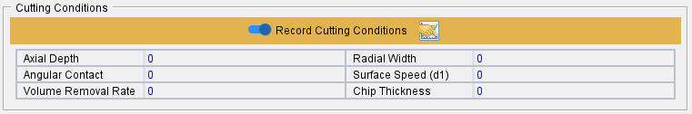
Select any of the following "cutting condition" features to be displayed in the Cutting Conditions graph. Each feature can be toggled On/Off at any time and the graph will be immediately updated.
Depth — The depth of cut.
Width — The width of cut.
Volume Removal Rate — Volume removal rate based on programmed values.
Chip Thickness — Chip thickness based on programmed values.
Feed Per Minute — Feed per minute based on programmed values.
Feed Per Tooth — Feed per tooth based on programmed values.
Feed Per Revolution — Feed per revolution based on programmed values.
Spindle Speed — Spindle speed.
Surface Speed — Surface speed.
Contact Area — The area of the tool that is in contact with the material.
OP Volume Removal Rate — Optimized volume removal rate, as calculated by Optimization.
OP Chip Thickness — Optimized chip thickness, as calculated by Optimization.
OP Feed Per Minute — Optimized feed per minute, as calculated by Optimization.
Op Feed Per Tooth — Optimized feed per tooth, as calculated by Optimization.
OP Feed Per Revolution — Optimized feed per revolution, as calculated by Optimization.
Show Tool Change — Use to show tool changes in the Cutting Conditions graph. Tool changes are represented by a vertical line, in the cut color, at the point of the tool change.