SubSystem Motion, SubSystem Motion panel
Location:
Info tab >  (SubSystem Motion)
Toolbar short cut: ![]()
The features on the SubSystem Motion panel are intended to assist you in debugging problems associated with the configuration of complex machines. In this context, “complex machines” means a multi-channel machine, or a machine which, at times, drive components other than their default components. This is a read only window. The information contained in the SubSystem Motion panel is updated as each block is processed.
The Subsystem Motion panel is one of the dockable panels enabling you to dock it inside the Vericut main window if you choose. See Personalizing the Vericut Main Window section of Vericut Help for additional information.
📝 NOTE: When the Subsystem Motion panel is docked, make sure that you click in the panel so that it becomes the "active" panel before using F1 to get help specific to the panel. Otherwise F1 will go to the Vericut Help Library.
 (Close) — Located at the end of the tab, this icon enables you to close the Subsystem Motion panel.
 (Close) — Closes the Subsystem Motion panel. This icon is only displayed when the Subsystem Motion panel is not docked.
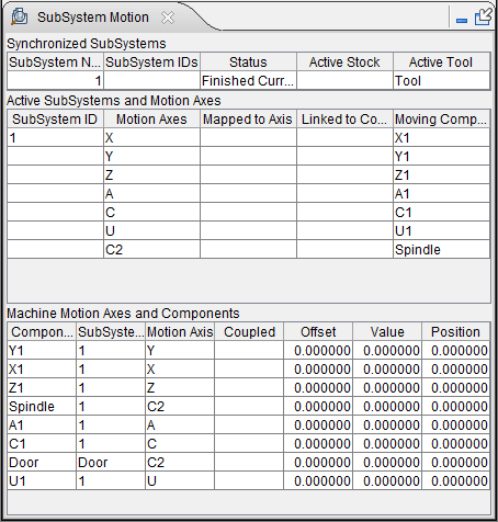
The panel is divided into 3 sections:
Each of these sections is described in detail in the sections that follow.
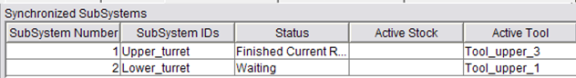
Synchronized SubSystems (Channels)
The Synchronized SubSystems (Channels) section of the window is only applicable if the current machine is a multi-channel machine. This section displays the different channels that are defined (referenced by a generic SubSystem Number), the SubSystem ID (or control) that they are associated with, and the current Status of this SubSystem. This section also displays the Active Stock component and the Active Tool.
All of this information can be found elsewhere in Vericut, but is repeated here because it forms the foundation from which other information will be built. The relationship between the Channel and the Subsystem is defined on the Control Settings window: Sync tab (Configuration tab > Control Settings).
The status of each SubSystem is also shown in both the Call Stack panel (Info tab > Call Stack), and in the NC Program panel (Info tab > NC Program).
The following Status conditions may be displayed:
Finished Current Record — This channel is waiting for more input.
Processing Current Record — This channel has data, and waiting for the other channels to get data before proceeding.
Waiting — This channel is sitting at a Sync Code, waiting on the other channels.
End Of File — This channel has reached the end of the file.
Active SubSystems and Motion Axes
Subsystems within Vericut are used to define inputs for separate controls, and are also used to define an additional 12 axes. For a multi-channel machine, only those controls defined in the channel section will be referenced in the Active SubSystems and Motion Axes section of the window. For a single channel machine, only the active control will be displayed in the Active SubSystems and Motion Axes section of the window. Each of the columns in the Active SubSystems and Motion Axes section of the Subsystem Motion panel are described below.
SubSystem ID — This column displays the SubSystem IDs that are being driven by each of the channels defined above in the Synchronized SubSystems (Channels) section of the window. Typically, these SubSystem IDs will match the SubSystem IDs listed in the Synchronized SubSystems (Channels) section of the window.
If the ChangeSubsystemID macro has been called, then the SubSystem ID that is being driven in the Active SubSystems and Motion Axes section of the window may be different then the SubSystem ID defined in the Synchronized SubSystems (Channels) section of the window.
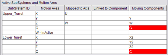
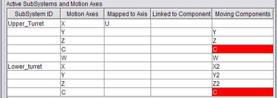
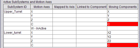
Motion Axis — This column displays all of the axes that exist for each SubSystem ID and whether the axes are currently active, or inactive. Axes that are currently inactive are marked as “Inactive” as shown in the picture below. Axes that do not exist for a specific SubSystem ID are not displayed.
📝 NOTE: Common mistakes include having multiple channels drive the same component, and incorrectly thinking that an axis is either active, or inactive, at a specific time for a specific channel, when in reality it is not the case.
Mapped to Axis — A common feature that exists on many machine/control configurations is to map one axis to drive another axis, for example the X-axis now drives the U-axis. One way to implement this within Vericut is to use the macro: SetAxisRegisterName. The Mapped to Axis column shows when this feature has been set for a specific axis on a specific channel. When it has, the register name will be shown.
The picture below shows that the X-axis has been mapped to the U-axis register for the Upper Turret.
📝 NOTE: The register name for a motion component is shown in its Component Type. For example: a Component Type of “Z Linear” is a linear component type being driven by the Z register.
Link to Component — A common feature that exists on many machine/control configurations is to link one axis to drive another axis, for example the Z-axis now drives the W-axis. One way to implement this within Vericut is to use the macro: SetAxisCompLink. The Linked to Component column shows when this feature has been set for a specific axis on a specific channel. If it has, the component name, and the Link formula will be shown.
The picture below shows that the Z-axis has been linked to the W component with a link formula of (2* $) for the Upper Turret.
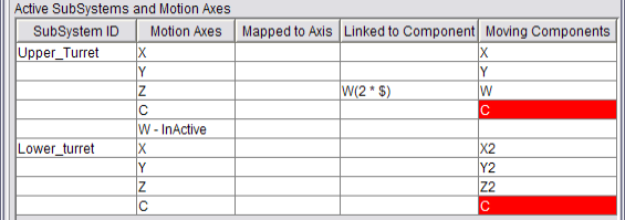
Moving Components — A component driven by a given axis can change based on the SubSystem ID, the Axis Mapping, the Link, the Couple Axis, and changes to the component tree. This column shows which component(s) are ultimately being driven by each axis. In this column, if the same component name is displayed more than once, then this is probably a problem and the cell will be highlighted red as shown in the picture below.
Both the Upper and Lower Turrets are driving the common C-axis. This should have been inactivated during the Start of Processing event for both channels.
Machine Motion Axes and Components
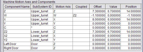
The Machine Motion Axes and Components section of the Subsystem Motion panel shows all of a machine’s motion components and various attributes and values for each component. The information in this section provides a low level picture of the machine. This information is not related to any control, and is only looking at the settings on the machine. The order of the components shown in the table is identical to the order in which they appear in the Machine branch of the Project Tree. Each of the columns in the Machine Motion Axes and Components section of the Subsystem Motion panel are described below.
Component Name — This column displays the name of the machine component.
Subsystem ID — This column displays the SubSystem ID of the subsystem (up to 12 axes) associated with the machine component.
📝 NOTE: This is a machine setting that is set using Project Tree, Configure Component menu: Component tab (for all motion components) and displayed in the Machine branch of the Project Tree. This value does not change.
Motion Axis — This column displays the Register associated with this machine component. For example: a Component Type of “Z Linear” is a linear component type being driven by the Z register.
📝 NOTE: This is a machine setting that is based on the Component Type set in the Project Tree, Configure Component menu: Component tab (for all motion components) and displayed in the Machine branch of the Project Tree. This value does not change.
Coupled — If a slave component is being coupled to a master axis, then the slave axis component name will be shown here for the corresponding master component.
One way to implement this within Vericut is to use the macro: CoupleAxisOn. The Coupled column shows when this feature has been set for a specific axis on a specific channel. When it has, the name of the slave component will be shown.
The picture below shows that the W-axis has been coupled to the Z2-axis Upper Turret.
📝 NOTE: When coupling has been established, it only applies to the machine, and not specific to any control.
Offset — The Offset column represents the actual “offset” value stored for the machine component.
Value — The Value column represents actual value stored for the machine component.
Position — The Position column represents the actual position of the machine component (the sum of the value in the Offset column and the value in the Value column).