Cutcom Sketch (Cutcom Sketch window)
Location:
Info tab >  (Cutcom Sketch)
Toolbar short cut: ![]()
The Cutcom Sketch window is a Cutter Compensation debugging tool that enables you to visually analyze:
-
The uncompensated tool path
-
The compensated tool path
The following simple example will show the features of the Cutcom Sketch window.
G41 X1 D1

  X3

G40 X4
Cutter Compensation looks at the entire motion from compensation on (G41) to compensation off (G40) and displays the information in the Cutcom Sketch window.
It is important to know that the sketch shows the true results both in the standard one-step look-ahead mode and in the full look-contour mode of cutter compensation.
The data file on which this visual tool is based is constantly updated during the cutter compensation mode; therefore it cannot be used before the cutter compensation mode ends. From the File menu the current sketch can be saved (under a different name) and later viewed in the Cutcom Sketch window. The file “cutcom_debug.swp” will be overwritten by the latest cutter compensated motion fragment.
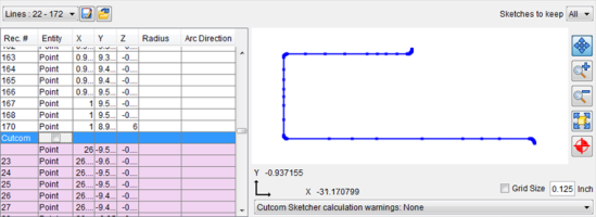
The blue line represents the uncompensated tool path, and is always displayed.
Toggle on (checked) Cutcom to display the uncompensated tool path (blue) and the actual compensated tool path (magenta) as shown in the picture below.
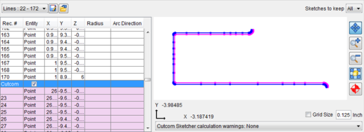
The pull-down list in the lower-right corner is used to list and highlight “bad”, or ill-defined, arcs (those with a non-positive radius, or those with a distance from an endpoint to the center different from radius). Note that “bad” arcs cannot be displayed as circular arcs by the sketcher, and are shown as linear segments.
![]() Save File — Save the current file.
Save File — Save the current file.
 Open File — Opens a file selection window enabling you to select another file.
Sketches to keep — Select from one of the following values: ALL saves all cutcom sketches, 0 saves and displays no cutcom sketches, or 1 saves and displays only the last cutcom sketch.