Comparator (Comparator window)
Location:
Analysis tab >  (Comparator)
Toolbar short cut: ![]()
The Comparator command button opens the Comparator window enabling you to select a DXF file containing a two-dimensional drawing, representing the design model, which you can overlay on the Stock model or the Cut Stock or to overlay a polar or rectangular grid over a workpiece or machine view to emulate an optical comparator chart.
Use this feature to measure distance and angular relationships of features on your part like you would with an optical comparator.
The grid can be displayed in any view but only in one view at a time. The grid is always displayed in the "active" view. The grid is always displayed parallel to the screen and its center (0,0) position is related to the origin of either the Attach Component for a Workpiece view and the Machine Origin for a Machine view.
The grid will be displayed as long as the Optical Comparator window is open. Closing the Optical Comparator window removes the grid from the display.
The following icon puts the Comparator window in DXF Comparator mode: ![]()
The following grid icons are used when the Comparator window is in Optical Comparator mode:
![]() — Displays a full polar grid.
— Displays a full polar grid.
![]() — Displays a polar grid with one linear grid quadrant.
— Displays a polar grid with one linear grid quadrant.
![]() — Displays a grid that is half polar and half linear.
— Displays a grid that is half polar and half linear.
![]() — Displays a linear grid with one polar quadrant.
— Displays a linear grid with one polar quadrant.
![]() — Displays a full linear grid.
— Displays a full linear grid.
 (Color Palette) — The Color Palette icon enables you to specify a color for the Optical Comparator grid.
The right side of the Color Palette icon shows the current color for the DXF Comparator overlay or the Optical Comparator grids. To change the color for the optical comparator grid, click on the (Color Palette) icon to display the color palette window shown below.
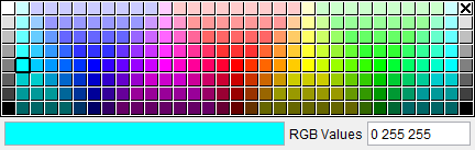
Click on a color in the color palette window, to specify the color for the optical comparator grid. The color palette window will close and the right side of the  (Color Palette) icon in the DXF Comparator window will update to reflect the selected color.
To close the color palette window without changing the color, click on the  in the upper right corner of the color palette window.
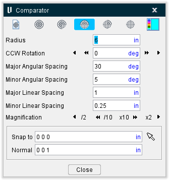
Use the following options to specify the size and position of the grid as well as define the spacing between major and minor grid lines. Units are the same as the workpiece or machine depending on the type of view that is "active".
Radius — Specify the radius of the grid that you want to display.
CCW Rotation — Use to rotate the grid about its center point. Enter an angle value in the text field. A positive number rotates the grid the specified number of degrees in a counterclockwise direction from its default (zero) position. A negative number rotates the grid the specified number of degrees in a clockwise direction from its default (zero) position.
You can also rotate the grid about its center by selecting one of the arrow buttons. Selecting either the < or > button rotates the grid clockwise or counterclockwise from its current position by the value specified for Minor Angular Spacing. Selecting either the << or >> button rotates the grid clockwise, or counterclockwise, from its current position by the value specified for Major Angular Spacing.
Major Angular Spacing — Specify the number of degrees between the "major" grid lines of a polar grid.
Minor Angular Spacing — Specify the number of degrees between the "minor" grid lines of a polar grid.
Major Linear Spacing — Specify the distance between "major" grid lines of a linear grid.
Minor Linear Spacing — Specify the distance between "minor." grid lines of a linear grid.
Magnification — Use this option to quickly change the size of the grid by either a factor of 2, or a factor of 10. Selecting either the < or > button reduces or enlarges the size of the grid by a factor of 2. Selecting either the << or >> button reduces or enlarges the size of the grid by a factor of 10.
Snap to — Use this option to center the grid on a specific feature of the workpiece or machine. Click on the text field so that it is highlighted. Select a feature in the graphics area and the grid center will move to that location. You can also enter the X, Y, and Z coordinates of the workpiece/machine coordinate system in the text field. Selecting the Snap to button (or <Enter> on the keyboard) moves the grid to the specified location.
Normal — Use this field to set the default CSYS for the Comparator.
OK — Saves the current settings and dismisses the Optical Comparator window.
Apply — Applies all of the current settings to the displayed grid without dismissing the Optical Comparator window. You can also use the
Cancel — Dismisses the Optical Comparator window without saving the settings.
DXF Comparator mode
Vericut Users:
Location:
Analysis tab >  (Comparator) > (DXF Comparator tab)
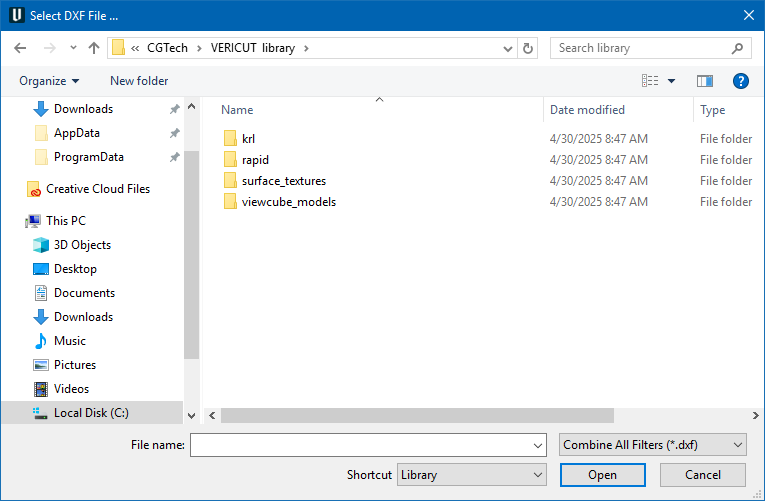
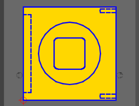
The DXF Comparator tab on the Comparator window opens the DXF Comparator File selection window enabling you to select a DXF file containing a two-dimensional drawing, representing the design model, which you can overlay on the Stock model / Cut Stock. Use this feature to compare the design to the cut stock.
📝 NOTE: Prior to selecting the DXF Comparator option, position the stock model/cut stock in the same orientation as the two-dimensional drawing contained in the DXF file. Typically you will select the Top, Right, Left, Front, Back, or Bottom orientation.
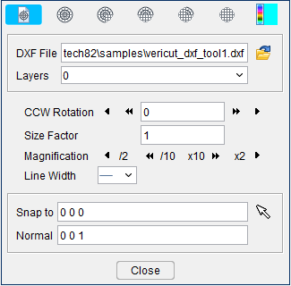
After you select a DXF file, the center of Comparator window display changes as shown in the picture below:
The overlay can be displayed only in the Workpiece view. The overlay is always displayed parallel to the screen and its origin (0, 0) position is positioned relative to the Workpiece Origin.
| Overlay on Stock Model | Overlay on Cut Stock |
|---|---|
 Placing the overlay over the Stock model enables you to compare each area to the design as the part is cut. Placing the overlay over the Stock model enables you to compare each area to the design as the part is cut. |
Placing the overlay of the Cut Stock enables you to compare the design with the finished part. |
The overlay will be displayed as long as the DXF Comparator window is open. Closing the DXF Comparator window removes the overlay from the display.
 (Color Palette) — The Color Palette icon enables you to specify a color for the overlay.
The right side of the Color Palette icon shows the current color for the overlay. To change the color for the overlay, click on the (Color Palette) icon to display the color palette window shown below.

Click on a color in the color palette window, to specify the color for the overlay. The color palette window will close and the right side of the  (Color Palette) icon in the DXF Comparator window will update to reflect the selected color.
To close the color palette window without changing the color, click on the  icon in the upper right corner of the color palette window.
Use the following options to specify the size, position, and scale of the overlay relative to the cut stock. Units are the same as the workpiece:
Center X — Use this feature to center of the overlay over the stock model/cut stock in the horizontal (X) direction. The value in the text field represents the current X location relative to the overlay’s origin.
You can move the horizontal position of the overlay’s origin by selecting one of the arrow buttons. Selecting either the < or > button moves the center of the overlay to the left or right of its current position by the value specified for Minor Linear Spacing. Selecting either the << or >> button moves the center of the overlay to the left, or right, of its current position by the value specified for Major Linear Spacing.
Center Y — Use this feature to center of the overlay over the stock model/cut stock in the vertical (Y) direction. The value in the text field represents the current Y location relative to the overlay’s origin.
You can move the vertical position of the overlay’s origin by selecting one of the arrow buttons. Selecting either the < or > button moves the center of the overlay down, or up, from its current position by the value specified for Minor Linear Spacing. Selecting either the << or >> button moves the center of the overlay down, or up, from its current position by the value specified for Major Linear Spacing.
Size Factor — Use this field to enter a number that will be used to magnify the size of the comparator overlay by. After entering the value, use the Enter key or the Apply button to apply the Size Factor to the overlay. Inputting the number 3, for example, will cause the comparator overlay to triple in size.
Magnification — Use this option to quickly change the size of the overlay. Selecting either the < or > button reduces or enlarges the size of the overlay by a factor of 2. Selecting either the << or >> button reduces or enlarges the size of the overlay by a factor of 10.
Line Width — Use this field to control the thickness of the comparator overlay. There are three possible sizes: thin, medium, and thick.
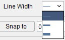
Snap to — Use this option to position the overlay’s origin on a specific feature of the stock model/cut stock. Click on the text field so that it is highlighted. Select a feature in the graphics area and the overlay’s origin will move to that location. You can also enter the X, Y, and Z coordinates (separated by blank spaces) of the desired location in the text field. Selecting the Snap to button (or
OK — Removes the overlay from the display and closes the Comparator window.
Apply — Applies all of the current settings to the displayed overlay without closing the Comparator window. You can also use the <Enter> key after changing an individual setting to immediately apply the change to the current overlay display.
Cancel — Removes the overlay from the display and closes the Comparator window.
Optical Comparator mode
Use the above grid features feature to measure distance and angular relationships of features on your part like you would with an optical comparator.
Comparator Grid Example
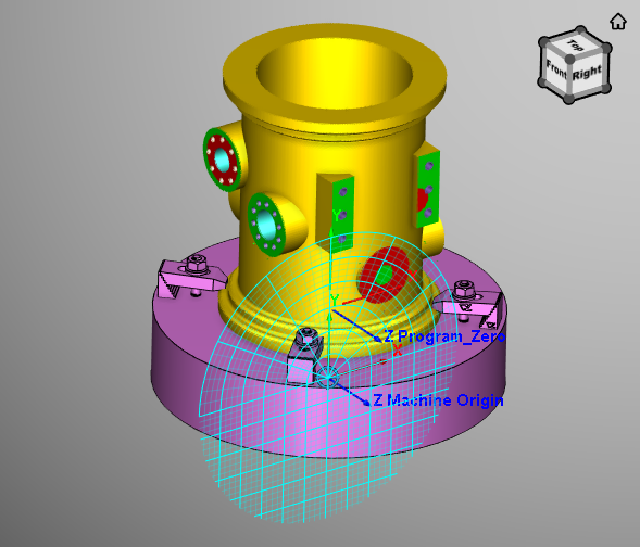
The grid can be displayed in any view but only in one view at a time. The grid is always displayed in the "active" view. The grid is always displayed parallel to the screen and its center (0,0) position is related to the origin of either the Attach Component for a Workpiece view and the Machine Origin for a Machine view.
The grid will be displayed as long as the Comparator window is open in Optical Comparator mode. Closing the Comparator window removes the grid from the display.
 (Color Palette) — The Color Palette icon enables you to specify a color for the grid. This feature applies to both DXF Comparator mode and Optical Comparator mode and is described in detail above.
Use the following options to specify the size and position of the grid as well as define the spacing between major and minor grid lines. Units are the same as the workpiece or machine depending on the type of view that is "active".
Radius — Specify the radius of the grid that you want to display.
Center X — Specify the horizontal position of the center of the grid. Enter a value in the text field. A negative number moves the center of the grid the specified number of units to the left of the coordinate system origin. A positive number moves the grid to the right.
You can also move the horizontal position of the grid center by selecting one of the arrow buttons. Selecting either the < or > button moves the center of the grid to the left or right of its current position by the value specified for Minor Linear Spacing. Selecting either the << or >> button moves the center of the grid to the left, or right, of its current position by the value specified for Major Linear Spacing.
Center Y — Specify the vertical position of the center of the grid. Enter a value in the text field. A negative number moves the center of the grid the specified number of units down from the coordinate system origin. A positive number moves the grid up.
You can also move the vertical position of the grid center by selecting one of the arrow buttons. Selecting either the < or > button moves the center of the grid down, or up, from its current position by the value specified for Minor Linear Spacing. Selecting either the << or >> button moves the center of the grid down, or up, from its current position by the value specified for Major Linear Spacing.
CCW Rotation — Use to rotate the grid about its center point. Enter an angle value in the CCW Rotation text field. A positive number rotates the grid the specified number of degrees in a counterclockwise direction from its default (zero) position. A negative number rotates the grid the specified number of degrees in a clockwise direction from its default (zero) position. Use the
You can also rotate the grid about its center by selecting one of the arrow buttons. Selecting either the < or > button rotates the grid clockwise or counterclockwise from its current position by the value specified for Minor Angular Spacing. Selecting either the << or >> button rotates the grid clockwise, or counterclockwise, from its current position by the value specified for Major Angular Spacing.
💡 Tip: Hold the cursor over any of the < or > buttons or the << or >> buttons in the Comparator window to display a tip explaining what the button does.
Major Angular Spacing — Specify the number of degrees between the "major" grid lines of a polar grid.
Minor Angular Spacing — Specify the number of degrees between the "minor" grid lines of a polar grid.
Major Linear Spacing — Specify the distance between "major" grid lines of a linear grid.
Minor Linear Spacing — Specify the distance between "minor." grid lines of a linear grid.
Magnification — Use this option to quickly change the size of the grid by either a factor of 2, or a factor of 10. Selecting either the < or > button reduces or enlarges the size of the grid by a factor of 2. Selecting either the << or >> button reduces or enlarges the size of the grid by a factor of 10.
💡 Tip: Hold the cursor over any of the < or > buttons or the << or >> buttons in the Comparator window to display a tip explaining what the button does.
Snap to — Use this option to center the grid on a specific feature of the workpiece or machine. Click on the text field so that it is highlighted. Select a feature in the graphics area and the grid center will move to that location. You can also enter the X, Y, and Z coordinates of the workpiece/machine coordinate system in the text field. Selecting the Snap to button (or <Enter> on the keyboard) moves the grid to the specified location.
OK — Saves the current settings and dismisses the Comparator window.
Apply — Applies all of the current settings to the displayed grid without dismissing the Comparator window. You can also use the <Enter> key after changing an individual setting to immediately apply the change to the current grid display.
Cancel — Removes the grid from the display and dismisses the Comparator window without saving the settings.