Stock/Model Info group
Location:
Tool Manager > X-Caliper tab > Stock/Model Info group
X-Caliper tab > Stock/Model Info group
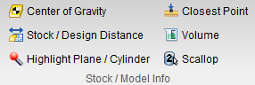
The command buttons in the Stock/Model Info group enable you to measure the distance between the Cut Stock and the Design model. To use this option the Design Visibility must be set to Workpiece View (Project Tree > Design > right click menu > Visibility).
📝 NOTE: Stock/Design Distance can only be used in a Workpiece view.
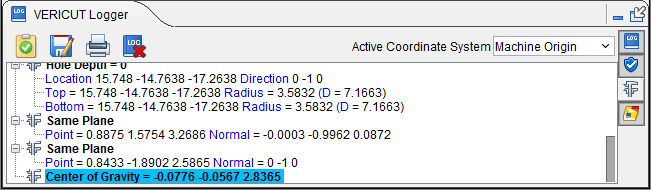
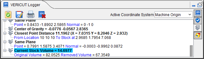
Center of Gravity — Reports X Y Z values of the calculated center of gravity point for the current cut stock model. If multiple cut stock models exist, user is prompted to select one. Center of Gravity is also a dimension that can be included in Vericut's Annotated Images. Information is also displayed in the Logger as shown below:
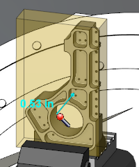
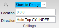
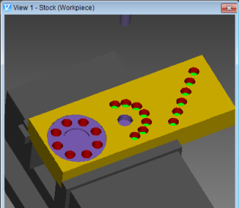
Stock/Design Distance — Specify whether to measure from the Cut Stock to the Design model, or to measure from the Design model to the Cut Stock. In the following picture the translucent green represents the Cut Stock and the solid magenta represents the Design model. Measurement is from the Stock to Design. Using the Stock/Design Distance command button, select a point on the Cut Stock model in the Workpiece view. This forms a measurement line and the From point and To point are symbolized as drawings on that measurement line.
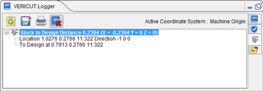
The information is then collected and displayed in the Vericut Logger panel as shown below:
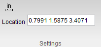
Information is also displayed in the Settings group as shown below:
-
Stock to Design/Design to Stock pulldown menu — Choose between these options to determine which direction the measurement will be taken in.
-
Location — Represents the XYZ coordinates of the point to measure from on the "From" component.
-
Direction — Represents IJK of the measurement direction vector toward the "To" component.
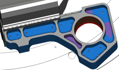
Highlight Plane/Cylinder — The Highlight Plane/Cylinder command button enables you to select a plane and have Vericut highlight all "cut" features that lie in the same plane. It also enables you to select a cylinder and Vericut will highlight all cylinders that have the same radius within the specified tolerance. Select Highlight Plane/Cylinder and then select any plane or cylinder on the stock workpiece in the Workpiece view window. The plane or cylinder and any related plane or cylinder will become highlighted in the color of your choice (specified in the X-Caliper Settings group).
-
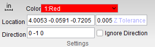
Color — Use to select the color to highlight the “same” planes/cylinders. Select the desired color from the pull-down color list.
-
Location — When selecting a plane, Location represents the XYZ coordinates of the screen pick.
When selecting a cylinder, Location represents the XYZ coordinates of the cylinder’s center. -
Direction — When selecting a plane, Direction represents the IJK values of the plane's normal vector at the location of the screen pick.
When selecting a cylinder, Direction represents the IJK values of the cylinder’s axis.
Data from the screen pick fills the Location and Direction data fields. -
Z Tolerance — When selecting a plane, use this field to specify a tolerance value for determining "same" planes. All planes, within ± the tolerance value, along the normal vector will be highlighted using the specified color.
When selecting a cylinder, use this field to specify a tolerance value for determining "same" cylinders. All cylinders, within ± the specified tolerance value, will be highlighted using the specified color. -
Ignore direction — Toggle on or off this option (checked or not checked) to ignore direction.
| Before selection: | After selection: |
|---|---|
 |
|
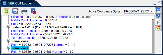
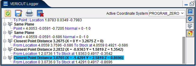
The information gathered is then displayed in the Vericut Logger panel as shown below:
📝 NOTE: Highlight Plane/Cylinder can only be used in a Workpiece view.
This information is also displayed in the X-Caliper Settings group as shown below:
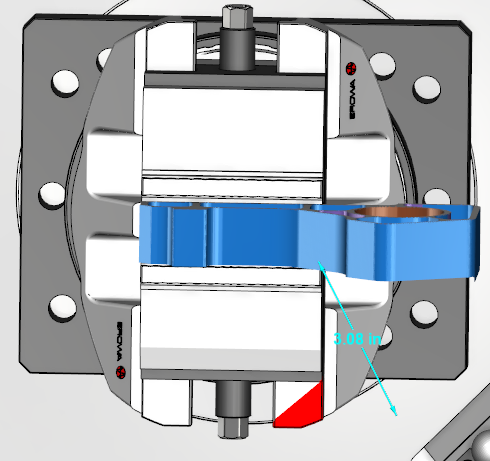
Sample Graphics display after using the Highlight Plane/Cylinder option on a cylinder:
Closest Point — The Closest Point command button is used to measure the shortest distance from an XYZ point location to the closest point on the model surface. In order to use the Closest Point option, Closest Point must be selected and then the XYZ coordinates of the “From” point must be entered into the Location text field in the X-Caliper Settings group. The Closest Point, "From" Location cannot be specified by selecting the location graphically.
Once the Location coordinates are input, hit the Enter key and a measurement line forms from the inputted coordinates to the closest point on the stock workpiece. The entry point, middle, and exit point are symbolized by the measurement line.
The information is then collected and displayed in the Vericut Logger window as shown below:
-
Closest Point — Represents the XYZ coordinates of the point at which the stock workpiece is closest to the From Location.
-
From Location — Represents the XYZ coordinates of the “From” point specified in the Location text field in the Settings group.
Measurement results are displayed in the Vericut Logger panel. Data output includes the From Location, the XYZ coordinates of the closest point on the model, and the measured distance between the From Location point and the Closest Point on the model.
Volume — The Volume command button calculates and displays the following volume values for a selected stock workpiece: current cut stock volume, original stock model volume, and volume of material removed from the original stock model. All volumes are in cubic units.
In addition to the total volume of the selected model, if the model consists of several disjointed pieces, the volume of a selected contiguous piece of material can also be analyzed. In this case, a bounding box is drawn around the selected piece to indicate what is being calculated. If the model is only one piece, no bounding box is drawn.
Select Volume and then click anywhere on a stock workpiece in the Workpiece view window to record the volume. The information collected will be displayed in the Vericut Logger panel as shown below:
📝 NOTE: Volume can only be measured in a Workpiece view.
Calculated volumes are displayed in the Vericut Logger panel. Data output includes the Current Stock Volume, Original Volume and Removed Volume.
-
Current Stock Volume — Displays the remaining total volume of the stock workpiece.
-
Original Volume — Displays the original total volume of the stock workpiece.
-
Removed Volume — Displays the total volume of material removed from the workpiece.
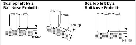
Scallop — The command buttons in the Scallop group are used to measure the height of a scallop formed by two parallel intersecting cylinders. Select the two parallel and intersecting cylinders on the Vericut model that form the scallop. X-Caliper identifies the cylinders being measured by displaying intersecting circles on the model as shown below:
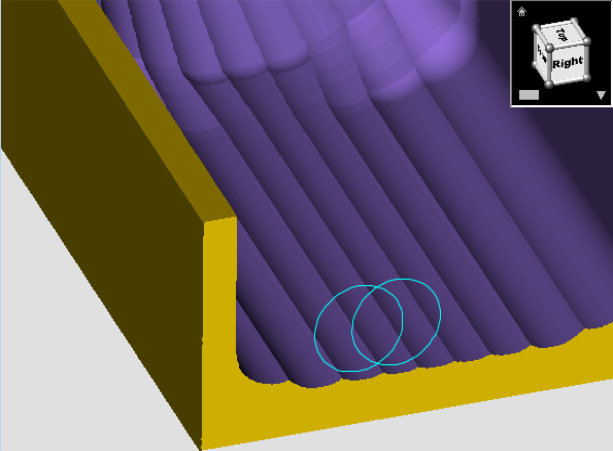
📝 NOTE: Machined features can only be measured in a workpiece view.
Use to define the two cylinders that will be used to calculate the Scallop Height. Select parallel cylinders on the Vericut model. After selecting Cylinder 1, Vericut displays a circle representing the cylinder in the graphics area and automatically transfers control to Cylinder 2. After selecting Cylinder 2, measurement results are displayed in the Vericut Logger panel as shown below:
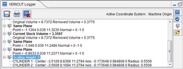
Data output includes Center point, Axis vector, and Radius values for each cylinder and the Scallop Height measurement.