Machine Settings (Machine Settings window)
Location:
Configuration tab >  (Machine Settings)
Toolbar short cut: ![]()
The Machine Settings command button opens the Machine Settings window enabling you to configure settings for an NC machine, such as: collision checking, travel limits, axis priority (for rapid motion), location tables, and when machine motions are simulated.
Machine Simulation On — When toggled "On", simulates machine tool motions when a 3-D machine is displayed in a machine view.
Light Environment — Use to specify which way is the light will shine within the program for a machine when a machine view displays walls in the background. (Ref. View tab > Attributes: Background). The axes direction is relative to the machine origin. Select the appropriate axis direction from the pull-down list.
Initialization File — Use this feature to specify the Machine Initialization File to be used. A Machine Initialization File is a text, or subroutine, file used to initialize variables used by the NC machine. The Machine Initialization File is processed at the same time as the "Start of Processing" event.
Click on the  (Add Machine Initialization File) icon to display the Machine Initialization Files file selection window and use it to specify the /path/filename of the Machine Initialization File to be used.
Use the ![]() (Clear Machine Initialization File) to clear the Initialization File text field.
(Clear Machine Initialization File) to clear the Initialization File text field.
Use the ![]() (Edit Machine Initialization File) to open the specified Machine Initialization File in a text editor window (ref. Text File in the Utilities tab section of Vericut Help for information on the text editor's features) to enable viewing and/or modifying it.
(Edit Machine Initialization File) to open the specified Machine Initialization File in a text editor window (ref. Text File in the Utilities tab section of Vericut Help for information on the text editor's features) to enable viewing and/or modifying it.
See Variables panel, in the Project Tree section of Vericut Help for information on monitoring and tracking Machine Variables.
See Initialization File in the Getting Started section of Vericut Help for additional information on Initialization Files.
Collision Detect tab — Features on this tab control when collisions between machine components are detected, which components are protected, and tolerances used for detecting collisions.
Travel Limits tab — Features on this tab define how far each machine axis can go, and control when travel limit errors are detected.
Axis Priority tab — Features on this tab control how machine axes move in rapid positioning mode (e.g. G0).
Subroutines tab — The features on this tab enable you specify machine related subroutines.
Machine Notes tab — Features on this tab are used to enter "message notes" and "comment notes" in the current machine file.
OK — Applies the changes and closes the Machine Settings window.
Apply — Applies the changes and leaves the Machine Settings window open.
Cancel — Closes the Machine Settings window without applying changes.
Machine Settings window, Collision Detect tab
Location:
Configuration tab >  (Machine Settings) > Collision Detect tab
Toolbar short cut: ![]()
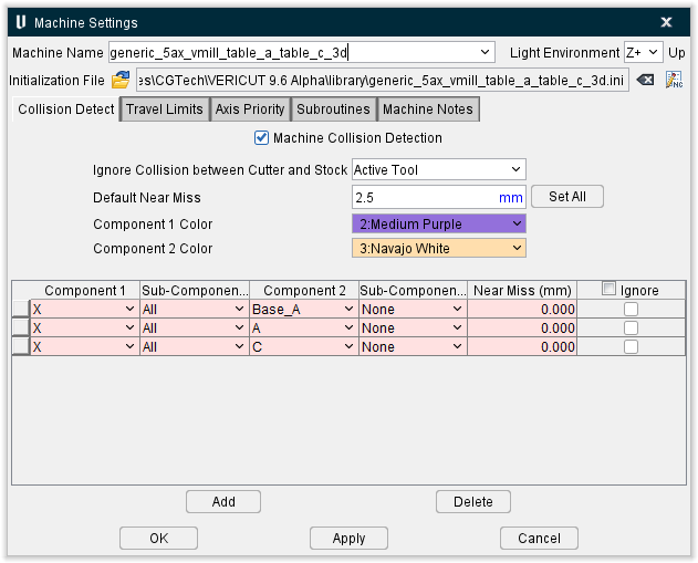
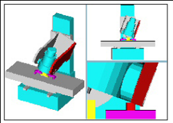
The features on the Collision Detect tab control when collisions between machine components are detected, which components are protected, and tolerances used for detecting collisions.

Colliding components are highlighted using the red Error color, and errors are issued to the Log file identifying collision causing block(s) and machine components.
Machine Collision Detection — When toggled "On", detects collisions between specified components.
Ignore Collision between Cutter and Stock — Controls when collisions between the cutter and the Stock component are ignored. This feature is useful when collision detection is desired between the stock and shank or holder portions of the tool assembly in the machine view, but not with the cutter. This feature is off by default. Options are:
-
No — (default) Does not ignore cutter-stock collisions. All collisions are reported.
-
All Tools — Ignores cutter-stock collisions for all tools, even inactive tools in multi-tool machines.
-
Active Tool — Ignores cutter-stock collisions for the active tool. However, collisions between stock and inactive tools are detected.
Default Near Miss — Specifies the default collision tolerance applied to all collision cases when Set All is pressed (see below).
Set All — Sets the default collision tolerance for all collision cases to the Default Near Miss value. You can edit the supplied tolerance for individual cases.
Component Colors — Use these fields to set the highlight color of the first and second component and any specified sub-components
Component/Component collision list
Lists the component-to-component collision cases that are checked when collision detection is turned on.
📝 NOTES:
-
Records displayed in pink are created, and modified, using the Machine Settings window: Collision Detect tab (Machine/Control tab > Machine Settings > Collision Detect tab) and saved in the machine file.
The Machine Settings window: Collision Detect tab and the Collision and Travel Limits window: Collision Detect tab (Project Tree: Collision branch right mouse button menu > Open) are linked so that whenever additions, or changes, are made in the Machine Settings window: Collision Detect tab they are also updated in the Collision and Travel Limits window: Collision Detect tab.
Pink records cannot be modified in the Collision and Travel Limits window: Collision Detect tab. -
Records displayed in white are part of the setup and can be created, or modified, in the Machine Settings window: Collision Detect tab or in the Collision and Travel Limits window: Collision Detect tab and are saved with the setup in the project file.
These two windows are linked so that whenever additions, or changes, are made to white records in one window they are updated in both windows when you select Apply or OK.
Component1/Component2 — These features are used to specify the component-to-component collision cases to check. Clicking on a component field in a record displays a pull-down list of components to choose from.
📝 NOTE: Do not configure for collision detection between components that move (slide or rotate) against each other, such as connected motion axes. In these cases, errors may occur each time the components move.
Sub-Component Range — Includes a range of Sub-Components of Component1/Component2 during collision checking.
-
None — Only Component1/Component2 will be included during collision checking.
-
All — All Sub-components of Component1/Component2 will be included during collision checking.
-
Down to
— Defines a range of Sub-components of Component1/Component2 to be included during collision checking that ends with (and includes) the specified Sub-Component.
E.G. For the below Project Tree: -
“X1” Down to “X3” means that “X1”, “X2”, and “X3” will be checked for collisions
-
“Base” Down to “Y2” means that “Base”, “Y0”, “Y1”, and Y2” will be checked for collisions
Near Miss — Use to specify a value that controls how close the components are permitted to be before reporting a collision. Enter a positive value to be alerted if components come near each other within the specified clearance, zero to indicate components may not touch.
Ignore — Then toggled “on” (checked), Vericut will ignore the specific collision record during collision checking. Ignore, when toggled “on”, only remains active for the current session. It is not saved in the project file.
Add — Adds a new collision case record to the list.
Delete — Deletes the selected collision case record from the list.
↘️ Shortcut: You can right-click in the Component/Component collision list to display the following menu.

These provide the same functionality described above.
Machine Settings window, Travel Limits tab
Location:
Machine/Control tab >  (Machine Settings) > Travel Limits
Toolbar short cut: ![]()
The features on the Travel Limits tab enable you to define travel limits for each machine axis, and control when, and under what conditions, travel limit checking is done and errors reported.
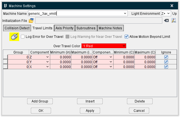
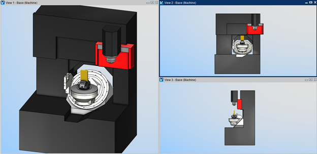
Overtravel errors cause the violating machine component to "light up" in the Overtravel Color and errors are output to the Log file identifying the problem component.
Log Error for Over Travel — When active, turns on overtravel detection (travel limit checking). Components that move beyond specified error limits are highlighted in the Overtravel Color and errors are issued to the Log file identifying error causing block(s) and machine components during simulation.
Log Warning for Near Over Travel — When active, it expands travel limit record table and turns on overtravel detection (warning limit checking). Components that move beyond specified Min/Max warning limits a warning are issued to the Log file identifying warning causing block(s) and machine components during simulation.
📝 NOTES: During simulation, Near Over Travel checking verification is automatically turn OFF depending for a single or all machine axis when one of these macros generates a motion. Then right after motion, verification is automatically turn back ON for next motions.
-
[X,Y,Z,A,B,C,U,W,V,W,A2,B2,B3]AxisMachineMotion
-
[X,Y,Z,U,V,W]AxisMotionLimit
-
ToolRetract
-
MachineRetract
-
TurretRetract
-
ReferencePoint
-
ReferencePointIndex
If machine axis travels beyond near travel limit and also over travel limit values, Vericut won’t generate unnecessary near travel warnings in the Log file in a case of errors.
During simulation, Near Over Travel checking verification is automatically turn OFF on a Tool Change Retract sequence for a single or all machine axis. Then right after motion, verification is automatically turn back ON for next motions.
Allow Motion Beyond Limit — When toggled "On", axes are allowed to freely travel beyond defined limits. When toggled "Off", an axis is never allowed to travel beyond the defined limit.
Overtravel Color — Use to specify the color in which components that move past their specified limits are shaded. Available shade colors are defined on the Configuration tab > Colors: Define tab.
Travel Limit Record Table
List of travel limit records in which each record consist of a group number, motion component (and its axis limits), travel limit condition and an ignore switch.
Group — Enables travel limit records to be grouped together. The default group ID is 0. You can change the group ID by clicking on the Group field of the highlighted record to put it in edit mode, and then enter the desired group number. A specific group of travel limit records is activated by using the TravelLimitsGroup macro. For information on the TravelLimitsGroup macro, and all Vericut macros, see Vericut Macros in the Vericut Help Library.
Component — Use to specify a motion component for travel limit checking. Click on the Component field of the highlighted record to put it in edit mode. Select the desired motion component from drop down list. The list contains of all motion components in the machine; linear, rotary or turret.
Minimum / Maximum — Use to specify the minimum, and maximum, travel limits for the motion axis selected in the list. Click on the Minimum/Maximum field of a highlighted record to put it in edit mode. Enter the desired axis limit.
The next three columns in the Travel Limit Record Table are used to specify conditions when the travel limit record is used. The condition can be set to "OFF" indicating no special condition for this record or set to a motion component on the machine.
When a motion component is specified, then the travel limit record is used if the axis of the conditional component is within the conditional minimum and maximum limit values.
Near Min. Warning / Near Max. Warning — Use to specify the minimum and maximum distance at which the program will alert you to a near over travel happening. This feature is used in conjunction with the Log Warning for Near Over Travel toggle at the top of the window. If that feature is toggled off (not checked) then these columns will not be present.
Component (C) — Use to specify a condition when the travel limit record is used. Set to "OFF" indicating no special condition for this record, or specify a conditional motion component on the machine. Click on the Component (C) field of the highlighted record to put it in edit mode. Select the conditional motion component from drop down list. The list contains of all motion components in the machine; linear, rotary or turret.
Minimum (C) / Maximum (C) — Use to specify the minimum, and maximum, travel limits for the conditional motion component (Component (C)). Click on the Minimum (C) / Maximum (C) field of a highlighted record to put it in edit mode. Enter the desired axis limit.
Ignore — When toggled "On", over travel checking is ignored for the corresponding axis.
Add Group — Use this feature to add a group of travel limit records. The number of travel limit records added will be equal to the number of motion components in the machine. The group number assigned will be the next available ascending group number in the list of travel limits.
For robots, associate A6 travel limits to the sum of A4+A6 angles — When toggled "on” (checked), the sum of angles associated to both A4 and A6 robot joints will be checked against travel limits set for A6 robot joint. It will also drive robot logic, to find the most appropriate solution for A6 rotation. This is useful for robot head having tubes coming from the creel house, which should not wrap around robot elbow.
Insert — Use this feature to add a travel limit record.
Delete — Use this feature to delete the selected travel limit record(s).
OK or Apply must be used to apply changes. If you use Cancel and have made changes but have not used OK or Apply, you will be queried whether or not you want to apply the changes before leaving.
Machine Settings window, Axis Priority tab
Location:
Machine/Control tab >  (Machine Settings) > Axis Priority
Toolbar short cut: ![]()
The features on the Axis Priority tab enable you to control how machine axes move in rapid positioning mode (e.g. G0). By default, machine axes are interpolated with equal priority to arrive at their destinations at the same time. You can change the priority to simulate non-interpolated rapid motion such as "dog leg" or "squared off" movement.
Each axis can have an unlimited number of priorities, each designated by a Group number. By default, each axis has a priority group designated as “0” which may not be deleted. All other groups can be added or deleted.
The priority group can be change at any time during the simulation using the AxisPriorityGroup macro. For information on AxisPriorityGroup, and all Vericut macros, see the Vericut Macros section in the Vericut Help Library.
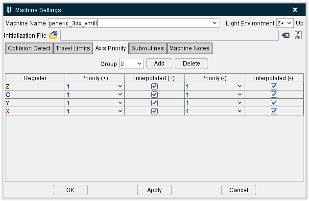
Group — The displayed value designates Axis Priority group currently being displayed. Click on the ![]() icon to display the list of Axis Priority groups that have been defined. Select the desired Axis Priority group from the pull-down list to change the group that is displayed.
icon to display the list of Axis Priority groups that have been defined. Select the desired Axis Priority group from the pull-down list to change the group that is displayed.
Add — Use to add a new Axis Priority group.
Delete — Use to delete the currently displayed Axis Priority group.
The Axis Priority list is a list of all applicable machine motion axes and the corresponding priorities for each.
Register — A list of all applicable machine motion axes.
Priority (+) — Use to specify the priority to be used when moving the specified motion axis in rapid when the tool is moving in the positive Z direction. A value of "1" moves that axis first. A "2" moves the axis with secondary priority (after those with priority "1"), and so on. Axes having the same priority move together.
Interpolated (+) — The checkbox settings in this column are used when the tool is moving in the positive Z direction. When toggled “on” (checked), axes that move together are interpolated such that they arrive at their destination at the same time. Clear this checkbox to have axes move based on their defined Rapid Rate (ref. Configure Component Menu > Component Type: All Motion Axes, in the Project Tree section of Vericut Help).
Priority (-) — Use to specify the priority to be used when moving the specified motion axis in rapid when the tool is moving in the negative Z direction. A value of "1" moves that axis first. A "2" moves the axis with secondary priority (after those with priority "1"), and so on. Axes having the same priority move together.
Interpolated (-) — The checkbox settings in this column are used when the tool is moving in the negative Z direction. When toggled “on” (checked), axes that move together are interpolated such that they arrive at their destination at the same time. Clear this checkbox to have axes move based on their defined Rapid Rate (ref. Configure Component Menu > Component Type: All Motion Axes, in the Project Tree section of Vericut Help).
Machine Settings window, Subroutines tab
Location:
Machine/Control tab >  (Machine Settings) > Subroutines
Toolbar short cut: ![]()
The features on the Subroutines tab enable you to specify the names of external files containing subroutines accessible by the NC machine.
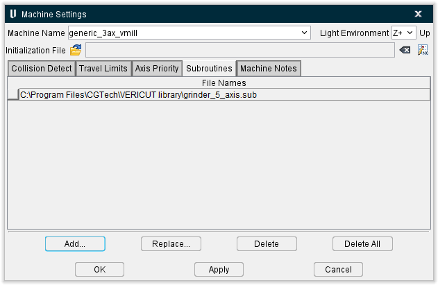
File Names list — List of external files containing subs accessible to Vericut.
↘️ Shortcut: Right-click in the File Names list area to display a pop-up window with the following features:

-
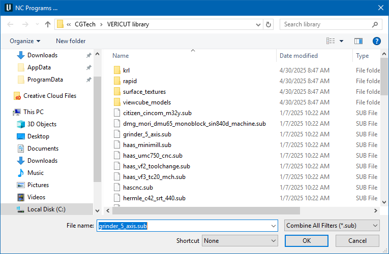
Add — Opens the NC Programs file selection window enabling you to add external subroutine files to the File Names list.
-
Replace — Opens the Machine Subroutine Files file selection window enabling you to replace the highlighted subroutine file in the File Names list with another.
-
Delete — Deletes the highlighted subroutine file from the File Names list.
-
Edit — Displays the of the highlighted subroutine file in a text editing window. Standard text editing features are provided, such as: copy/cut, paste, search, etc. For more information on using the editing features see Utilities tab > Text File.
Add — Opens the NC Programs file selection window enabling you to add external subroutine files to the File Names list. (Same as Add in the pop-up window described above)
Replace — Opens the Machine Subroutine Files file selection window enabling you to replace the highlighted subroutine file in the File Names list with another. (Same as Replace in the pop-up window described above)
Delete — Deletes the highlighted subroutine file from the File Names list. (same as Delete in the pop-up window described above)
Delete All — Deletes all subroutines files from the File Names list.
Machine Subroutine Files File Selection Window
- Select the
 (Folder) tab if the folder tree is not already displayed.
 -
Select the folder in the folder tree on the left side of the window containing the machine subroutine file(s) that you want to open. Use the
 (Up One Level) icon, located above the folder tree, to quickly move up one level in the folder tree structure.
You can also select the folder from the Shortcut pull-down list, located above the folder tree, if it is found there.
Finally you can select the (Favorite) tab to display your “Favorite” folder tree.
See Favorites panel in the Configuration tab section of Vericut Help for information on creating a Favorites folder.
The (Add a Favorite) icon is used to Opens the Add a Favorite window enabling you to add a “favorite” folder or “favorite” file to your Favorites panel. A ”favorite” is a link to a folder of files or a link to an individual file.
 -
Once you select the folder in the folder tree, the files in that folder are displayed in the center section of the file selection window. Use the Filter feature to specify the type of files that you want displayed.
-
Select one, or more, files that you want to add to the current Setup from those displayed in the center section of the file selection window so that they become highlighted.
Use the <Shift> key to select a range of files. Select the first file in the range, and then hold down thekey while selecting the last file in the range.
Press and hold the <Control> key while selecting multiple individual files. -
The right side of the file selection window shows the machine subroutine files that are currently associated with the current Setup. Use the
 to add the machine subroutine files highlighted in the center section of the file selection window to the Current Machine Subroutine Files list.
Use the to remove highlighted machine subroutine files from the Current Machine Subroutine Files list.
The files are added to the File Names list in the Machine Settings window: Subroutines tab in the order that they appear in the Current Machine Subroutine Files list. To change the order of the files in the Current Machine Subroutine Files list, click on the square button to the left of the file name and drag it to the desired position in the list. -
Click on the OK at the bottom of the window to add all of the files in the Current Machine Subroutine Files list to the File Names list in the Machine Settings window: Subroutines tab and close the file selection window.
- You can click on Cancel at the bottom of the window to close the file selection window without making any machine subroutine file changes.
Add, Modify, or Delete Machine Subroutine Files
Machine Subroutine Files are external files containing subroutines accessible by the NC machine.
To add a machine subroutine file to the machine file:
-
To add a machine subroutine file, in the Machine Settings window: Subroutines tab click on the Add button to display the Machine Subroutine Files file selection window.
You can also right-click in the File Names list area and select Add from the menu that displays, to display the Machine Subroutine Files file selection window. -
In the Machine Subroutine Files file selection window that displays, select the machine subroutine file(s) to be added, then click OK. If needed, refer to Machine Subroutine Files File Selection Window section of Vericut Help.
The new machine subroutine file name(s) are added to the File Names list on the Machine Settings window: Subroutines tab.
Make sure that you save the machine file to update the machine subroutines referenced by the machine file.
To replace a machine subroutine file in the File Names list with a different file:
-
To replace a machine subroutine file with another, in the Machine Settings window: Subroutines tab, click on the machine subroutine file in the File Names list that is to be replaced so that it becomes highlighted and then select Replace to display the Machine Subroutine Files file selection window.
You can also click on the machine subroutine file in the File Names list that is to be replaced so that it becomes highlighted and then right-click in the File names list area and select Replace in the menu that displays to display the Machine Subroutine Files file selection window. -
In the Machine Subroutine Files file selection window that displays, type, or select the /path/filename of the replacement NC program file, and then click OK. If needed, refer to Machine Subroutine Files File Selection Window section of Vericut Help.
The replacement machine subroutine file name is added to the File Names list on the Machine Settings window: Subroutines tab.
Make sure that you save the machine file to update the machine subroutines referenced by the machine file.
To delete a machine subroutine file from the File Names list:
To delete a machine subroutine file in the Machine Settings window: Subroutines tab, click on the machine subroutine file in the File Names list that is to be deleted so that it becomes highlighted and then select Delete to delete the file from the File Names list.
You can also click on the machine subroutine file in the File Names list that is to be deleted so that it becomes highlighted and then right-click in the File Names list area and select Delete in the menu that displays to delete the file from the File Names list.
To delete all machine subroutines from the Machine Settings window: Subroutines tab File Names list, click on the Delete All button. All machine subroutine files are removed from the File Names list.
Deleting subroutine files from the Vericut configuration does not delete the files from your computer.
Make sure that you save the machine file to update the machine subroutines referenced by the machine file.
To edit a machine subroutine from within Vericut:
-
To edit a machine subroutine, in the Machine Settings window: Subroutines tab right-click on the machine subroutine in the File Names list that is to be edited and then select Edit from the menu that displays.
-
The contents of the machine subroutine file will display in a text editor window. (see Text File in the Utilities tab section of Vericut Help for information about the text editor window). Edit the contents of the machine subroutine file as necessary. When finished editing, select the Save File icon (or Save As File icon) in the text editor main menu to save your changes.
- Select Exit in the text editor main menu to close the text editor window.
Also see Advanced Control Options window: Subroutines tab and Add, Modify, or Delete Control Subroutines, in the Machine/Control tab section of Vericut Help, for information about "control “subroutines.
Also see Configure NC Subroutines Branch menu in the Project Tree section of Vericut Help, for information about "NC subroutine" files.
Machine Settings window, Machine Notes tab
Location:
Machine/Control tab >  (Machine Settings) > Machine Notes
The features on the Machine Notes tab enable you to add Message Notes and Comment Notes to the machine file.
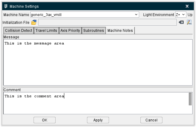
Message Notes are saved in the header of the machine file and are displayed in the Vericut message area (Logger) when the machine file is loaded.
Comment Notes are saved in the header of the machine file but do not display in the Vericut Logger.
There is a limit of 255 characters per line, but there is no limit to the number of lines that can be added.
Any Message/Comment Notes that currently exist in the machine file are displayed in the appropriate text field as shown below. Any note can be edited and re-saved in the machine file.
Existing Message/Comment Notes in the machine file:
In the machine file, each line of the note is added to the header in quotes, and is preceded by either the keyword MESSAGE (for message notes), or COMMENT (for comment notes).
How the above messages look in the machine file:
Adding /editing notes:
Add a note by typing the desired text, or edit the text of existing notes in the appropriate text field. When finished, press OK, or Apply, depending on whether or not you want to leave the Machine Settings window open. Then save the machine file using the Machine/Control tab > Save Machine (or Save As) feature in the menu ribbon, or use the ![]() (Save Machine) or
(Save Machine) or ![]() (Save Machine As) icon in the tool bar.
(Save Machine As) icon in the tool bar.