Die Sinking Simulation window
Locations:
Project Tree > Setup Branch Right Mouse Shortcut Menu > Die Sinking
Utilities tab >  (Die Sinking Simulation)
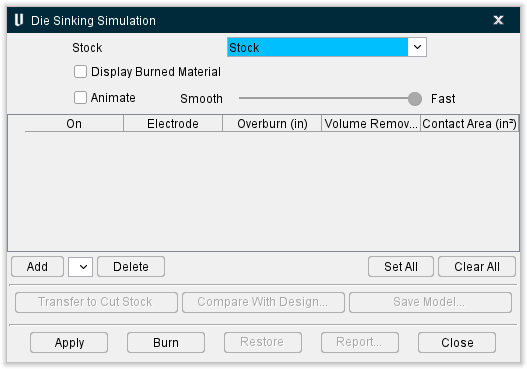
The features on the Die Sinking Simulation window enable you to select electrodes and simulate the die sinking process.
Simulation Display Features
Stock — Enables you to select the Stock component that is to be used for the simulation. Select the name of the Stock component from the pull-down list.
Display Stock — use to specify whether or not to display the Stock model during the simulation. The stock model can be displayed as Solid or Translucent. The stock model remains displayed during the Burn process unless Display Burned Material is toggled on. In this case the Stock model will be turned off when you select Burn and only the material removed by the simulated EDM burn will be displayed at the end of the burn process.
Display Electrodes — use to specify whether or not to display the Electrode model(s). Electrode models can be displayed as Solid or Translucent. Electrode models are always toggled off after Burn is selected.
Display Burned Material — use to specify whether or not to display the material that is removed by each electrode during the simulation. The "burned material" can be displayed as Solid or Translucent.
Animate — use to specify whether or not to display electrode animation during the "burn" process. Use the slider bar to control the speed of the animation. If toggled off, displays only the result of the burn process.
Electrode Table
Table of electrodes selected for use during Die Sinking Simulation.
On — Toggles on and off to activate/deactivate individual electrodes in the table. Only the active electrodes will be used during the "burn" process.
Electrode — The name of the electrode component.
Overburn — this column enables you to specify an "overburn" value for each electrode. The "overburn" value is applied as an offset to each electrode during "burn" processing.
Volume Removed — this column displays the volume of material that was removed by each active electrode during the burn process. The "volume removed" value is updated in the table as each electrode completes the burn process.
Contact Area — this column displays the area of material that was removed by each active electrode during the burn process. The "contact area" value is updated in the table as each electrode completes the burn process.
Click and drag the button in the first column of each row to change position of an electrode in the table. "Active" electrodes will be processed sequentially starting at the top of the table.
Add — use to add additional electrodes to the table. Select the electrode to be added from the pull-down list then select Add. The pull-down list will contain all electrode components found in the Component Tree that are not currently in the table.
Delete — use to remove the highlighted electrode from the table.
↘️ Shortcut: You can right-click in the Electrode table to display a menu containing Add and Delete. These provide the same functionality described above. Clicking on Add will display the pull-down list of available electrodes that you can choose to add to the table.
Set All — use to activate "all" electrodes in the table.
Clear All — use to deactivate "all" electrodes in the table.
Die Sinking Simulation features
Compare With Design — displays the AUTO-DIFF window enabling you to compare the stock model at the end of the burn process with the design model.
Save Model — enables you to save the stock model that resulted from the burn process as a Vericut solid (.vct) file.
Apply — Use to save the current Die Sinking Simulation settings.
Burn — Use to start the "burn" process.
Restore — Restores the stock model to the state it was in prior to the "burn" process.
Report — Use to create a Die Sinking Simulation Report. A sample Die Sinking Simulation Report can be found here.
Close — Closes the Die Sinking Simulation window.