Import CAD Tool window
Locations:
Project tab >  (Tools) > Import tab > (Import CAD Tool)
The features on the Import CAD Tool window enable you to read, extract, identify tool insert and holder solid models from a CAD system, and then import them into Vericut's Tool Manager. STEP, CATIA V5, CREO, NX, and Solidworks files are supported. The Import CAD Tool window also features a Tool Display Area on the right so that you can view imported tools.
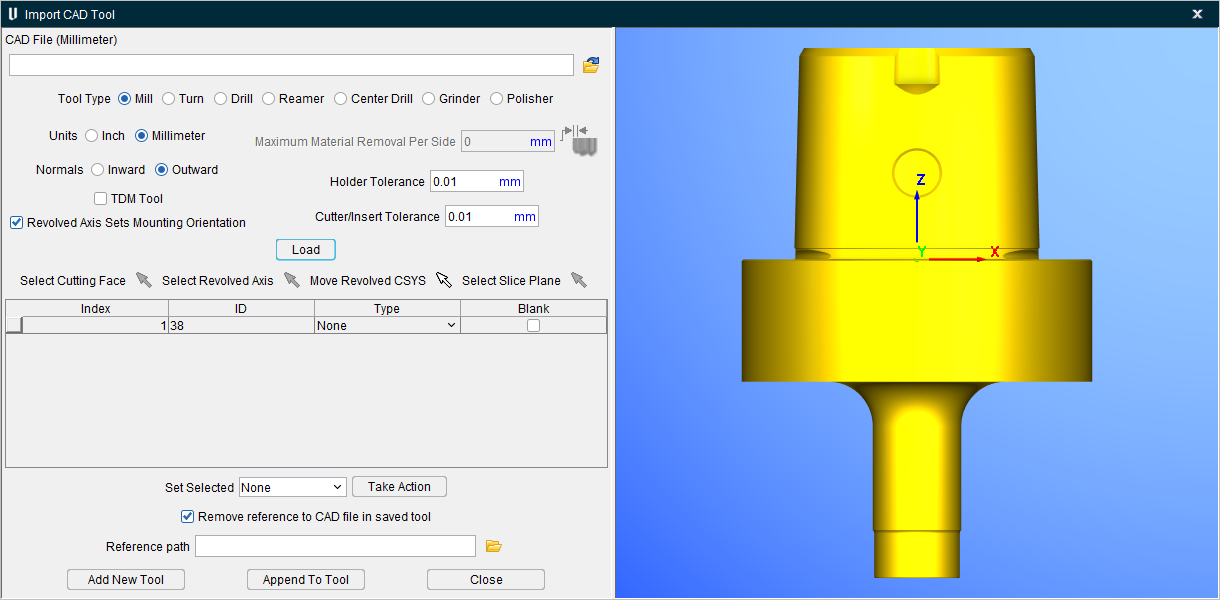
CAD File — Use to specify the CAD file containing the tool data. Enter the /path/filename in the CAD File text field or click on the  (Browse) icon and use the Select CAD File file selection window to specify the /path/filename. Once a CAD file is selected the units of that CAD file will appear in parentheses next to the CAD File text.
Tool Type — Select Mill, Turn, Drill, Reamer, or Central Drill to specify, the "type" of tool being imported into Tool Manager.
Units — Use to specify which "units" the tool is to be displayed for that particular tool into Tool Manager. Select Inch or Millimeter. This is not the incoming units of the CAD model file since that is determined by reading the unit setting in the CAD file.
Normals — Select Inward or Outward to specify the direction of surface normal vector relative to the material. Use Inward to specify that the surface normal vectors point inward towards the material, or Outward if the surface normal vectors point away from material.
TDM Tool — When toggled on (checked) enables reading TDM tools into CAD Tool Import.
The following rules must be followed when creating tools in TDM for import into the Import CAD Tool window:
-
All inserts for mill tools and turning tools will have their contours colored “green,” RGB = (0,1,0).
-
Contours representing the revolved profile for a mill tool, that is not a revolved insert, will have their color set to “red,” RGB = (1,0,0).
- All contours for inserts will lie on the insert face for both mill tools and turning tools.
Revolved Axis Set Mounting Orientation — When toggled on (checked) the milling tool will be oriented about the revolved axis. This is the default. When toggled off (unchecked) the milling tool will be oriented as it is defined in the STEP file.
Maximum Material Removed Per Side — Enables you to set a maximum amount of material to remove. This option is only enabled when Reamer is selected as the Tool Type.
Holder Tolerance — Enables you to specify the holder tolerance by entering the tolerance value into the Holder Tolerance text field.
Cutter/Insert Tolerance — Enables you to specify the cutter and insert tolerances by entering the tolerance value into the Cutter/Insert Tolerance text field.
📝 NOTE: By default, the values for the Holder Tolerance and Cutter/Insert Tolerance are read from the Preferences window in Tool Manager. If changes are made to these fields in the Import CAD Tool window, these changes will reflect anywhere the Holder Tolerance and Cutter/Insert Tolerance values are used. This includes various other.
Load — Reads the specified CAD File, identifies and extracts all solid bodies and then populates the table and displays all solid bodies in the Tool Manager Tool Display area.
Select Cutting Face ![]() — For each "Insert" type component, use the Select Cutting Face icon to initiate the picking sequence. Pick one or more surfaces representing the cutting face of the insert. When finished selecting the faces that represent the cutting face, click on the Select Cutting Face icon again to end the picking sequence. You can also end the cutting sequence by selecting the <Esc> key on your keyboard. This feature is only active when an "Insert" type component is highlighted in the Component Table.
— For each "Insert" type component, use the Select Cutting Face icon to initiate the picking sequence. Pick one or more surfaces representing the cutting face of the insert. When finished selecting the faces that represent the cutting face, click on the Select Cutting Face icon again to end the picking sequence. You can also end the cutting sequence by selecting the <Esc> key on your keyboard. This feature is only active when an "Insert" type component is highlighted in the Component Table.
📝 NOTE: This process should be repeated for each imported insert that is included in the tool assembly you are importing.
| Single Surface Cutting Face | Multiple Surface Cutting Face |
|---|---|
 |
 |
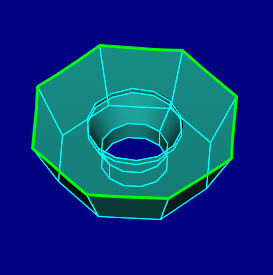
Select Revolved Axis ![]() — For each "Revolved" or “Holder” type component, use the Select Revolved Axis icon to display a coordinate system on the tool displayed in the Tool Manager Tool Display area enabling you to select the rotation axis of the revolved cutter. Vericut will then create a profile, similar to a profile created using the Profile Sketcher, for the revolved cutter. Vericut will then use the profile to calculate material removal. This feature is only active when a "Revolved" or “Holder” type component is highlighted in the Component Table.
— For each "Revolved" or “Holder” type component, use the Select Revolved Axis icon to display a coordinate system on the tool displayed in the Tool Manager Tool Display area enabling you to select the rotation axis of the revolved cutter. Vericut will then create a profile, similar to a profile created using the Profile Sketcher, for the revolved cutter. Vericut will then use the profile to calculate material removal. This feature is only active when a "Revolved" or “Holder” type component is highlighted in the Component Table.
Move Revolved CSYS ![]() — This feature enables you to move the “revolved CSYS” based on interactive mouse picks. The user will be prompted with 2 prompts to select surfaces to realign the coordinate system if it is oriented incorrectly in the imported model file.
— This feature enables you to move the “revolved CSYS” based on interactive mouse picks. The user will be prompted with 2 prompts to select surfaces to realign the coordinate system if it is oriented incorrectly in the imported model file.
-
Pick the XY Plane — select a surface that will align with the location of the XY plane.
-
Pick cylinder/cone face — select a surface that revolves around the center axis of the tool. This option can be used in conjunction with the Select Slice Plane if necessary or by itself.
Select Slice Plane ![]() — Sometimes using the Select Revolved Axis tool results in an unclear or asymmetrical profile as shown in the picture below. Notice the two areas circled in red. The two irregularities are caused by features on the Tool Holder.
— Sometimes using the Select Revolved Axis tool results in an unclear or asymmetrical profile as shown in the picture below. Notice the two areas circled in red. The two irregularities are caused by features on the Tool Holder.
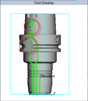
The Select Slice Plane feature enables you to rotate the “slice” plane about the selected revolved axis until the slice plane forms a clear and symmetrical image. See the pictures below.
|
|
|---|---|
Component Table
After specifying the CAD file, a record is created in the Component Table for each solid body contained in the file. You can re-order the records in the table by clicking on the button in the first column of the record and dragging it to the desired position.
Index — Represents the position of CAD solid body in the CAD File. For example, Index = 1 represents the first tool component in the CAD file, Index = 2 represents the second tool component in the CAD file, etc.
ID — CAD solid body ID
Type — For each body in the table, select its "Type".
-
None — The None type indicates that nothing is to be done with the model. Any body in the table designated as type "None" will NOT be transferred to Vericut's Tool Manager.
-
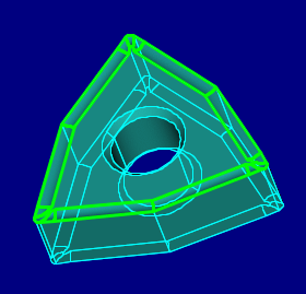
Insert — The Insert type is used for a model representing a relatively "flat" looking insert that is mounted in a holder. NOT something that is already "spun".
Use the Select Cutting Face feature to select curves that represent the "top" cutting edges of the insert.
The tool is imported as an "Insert Cutter" in Tool Manager.
The model is imported as a 3D polygon file (.ply extension).
The "Cutting Face" is imported as a 2D sweep profile. -
Holder — The Holder type is used for a model representing an object that holds another object (typically another holder, a cutter, or an insert).
The tool is imported as a "Holder" in Tool Manager.
The model is imported as a 3D polygon file (.ply extension). -
Shank — The Shank type is used for a model representing the portion of the tool assembly that extends above the cutter, and into the holder.
-
Revolved — The Revolved type is used for a model representing a typically "round" looking cutter which is "spun" around a centerline.
Use the Select Revolved Axis feature to select the rotation axis of the revolved cutter.
Vericut will “slice” through the model with a plane which passes through rotation axis and one of the other axes of the displayed coordinate system to create a profile.
The tool is imported as a "Revolved Cutter" in Tool Manager.
The model is imported as a 3D polygon shape/file (.ply extension). -
Blank — If unchecked, then the solid body is displayed in the Import CAD Tool window display area. If checked, then the solid body is NOT displayed.
📝 NOTE: The CAD File may contain multiple CAD solid bodies with the same ID. So, to uniquely identify the CAD solid bodies, the CAD solid body occurrence (Index) in the CAD File is used along with the CAD solid body ID to uniquely identify it.
Set Selected — This feature enables you to specify the Type or Blank features described above, to a selected group of solid bodies in the Component Table at once.
-
None — Use to set all of the selected bodies to Type: None.
-
Insert — Use to set all of the selected bodies to Type: Insert.
-
Holder — Use to set all of the selected bodies to Type: Holder.
-
Revolved — Use to set all of the selected bodies to Type: Revolved.
-
Blank Off — Use to toggle “off” (not checked) the Blank feature for all of the selected bodies.
-
Blank On — Use to toggle “on” (checked) the Blank feature for all of the selected bodies.
Take Action — Use to apply the Set Selected settings, above, to the bodies selected in the Component Table.
Example 1:
The following describes how to set a group of bodies in the Component Table to Type: Insert.
-
In the Component Table, select the bodies that you want to set as Inserts.
📝 NOTE: Hold the Shift key to select the first and last lines of the entire desired range in the Component Table. Hold the Ctrl key to select multiple, individual lines in the Component Table. -
Select Insert from the Set Selected pull-down list.
- Click on the Take Action button set the selected bodies in the Component Table to Type = Insert.
Example 2:
The following describes how to toggle “on” (checked) the Blank feature for a group of bodies in the Component Table so they are NOT displayed in the Tool Manager Tool Display area..
-
In the Component Table, select the bodies that you want to set as Blank.
-
Select Blank On from the Set Selected pull-down list.
- Click on the Take Action button set the selected bodies in the Component Table to Blank = checked (on). The selected bodies are now “blanked” (not displayed) in the Tool Manager Tool Display area.
Remove reference to CAD file in the saved tool — When toggled "off" (un-checked), the imported tool components are stored in the same CAD format that they were imported in. When toggled "on" (checked), the imported tool components are saved as Vericut Polygon files.
NOTES:
Import CAD Tool Import uses the same tolerance values as the rest of Tool Manager. The tolerance used depends on whether the Tool Manager internal to Vericut is being used or if stand-alone Tool Manager is being used.
-
When the Tool Manager internal to Vericut is being used, the Model Tolerance value for the current setup that is specified in the Settings window: Properties tab (Project tab > Settings) is used when creating the Vericut Polygon (.ply) files.
-
When stand-alone Tool Manager is used, the tolerance value is hard coded to either 0.025 for Metric units, or 0.001 for Inch units, depending on the specified unit type.
The unit type (Metric or Inch) is defined using the environment variable "CGTECH_DEFAULT_UNITS" which should be set to "MILLIMETER" or "INCH".
Reference path — The user can specify a path to where the polygon files will be saved. Reference path is only applicable when the “Remove reference to CAD file in saved tool” is toggled on (checked).
Add New Tool — Creates a new tool in Tool Manager with all table entries not defined as Type = "None".
Append To Tool — Appends all table entries not defined as Type = "None" to the currently selected tool in Tool Manager.
Cancel — Closes the CAD Geometry window.
See Import CAD Tool Component Models Using the CAD Geometry window section of Vericut Help for information about using the Milling Tool Wizard.