3DEXPERIENCE-to-Vericut Interface (CATV6_3dx)
Overview CATV6_3dx is an interface that facilitates the transfer of Fixture, Stock, Design, and 3D tool representations from the 3DEXPERIENCE manufacturing process to Vericut.
Available Interfaces: Vericut provides two interfaces for 3DEXPERIENCE:
CATV6_3dx: Standard interface for direct data transfer
CATV6_3dxml: Alternative interface for 3DXML-based data transfer
Software Requirements: CATV6_3dx Interface
Licensing Requirements
CGTech Licensing:
CATIA V6 Interface
Dassault Systems Licensing: One of the following is required:
NC Numerical Control Engineering (NCE)
NC Machine Simulation Engineer (NMN)
Installation & Configuration: CATV6_3dx Interface
User Configuration
No manual configuration required
The interface is pre-configured for seamless operation.
Installation Path
The interface installation files are located at:
C:\Program Files\CGTech\Vericut x.x.x\windows64\CATV6_3dx
To access version details, use:
C:\Program Files\CGTech\Vericut x.x.x\windows64\commands\catv6_3dx_version.bat
Environment variables: CATV6_3dx Interface
To enable the 3DEXPERIENCE Interface to locate the necessary Vericut files, the following environment variables must be defined:
Environment Variables: Description & Example
CGTECH_INSTALL
Purpose: Defines the Vericut installation folder.
Example: For Vericut 9.7, set to: C:\Program Files\CGTech\Vericut 9.7
CGTECH_PRODUCTS
Purpose: Specifies the folder for the operating system running Vericut (windows64).
Example: For Vericut 9.7, set to:
C:\Program Files\CGTech\Vericut 9.7\windows64
LSHOST
Purpose: Defines the name of the license server computer.
Example: localhost
CGTECH_SINGLE_PLATFORM (Optional)
Purpose: Specifies if Vericut is running on a single platform.
Example: CGTECH_SINGLE_PLATFORM=YES
CATV_LANGUAGE (Optional)
Purpose: Allows the interface to use a localized language file instead of US English.
Note: The application also provides the option to change the language directly from within the user interface but the path to the language local files must be set when using any other language then English.
Available Languages: French, German, Italian, Portuguese, Chinese, Japanese.
Example For Vericut 9.7, set to:
C:\Program Files\CGTech\Vericut 9.7\windows64\CATV6_3dx\CatvFrench.local
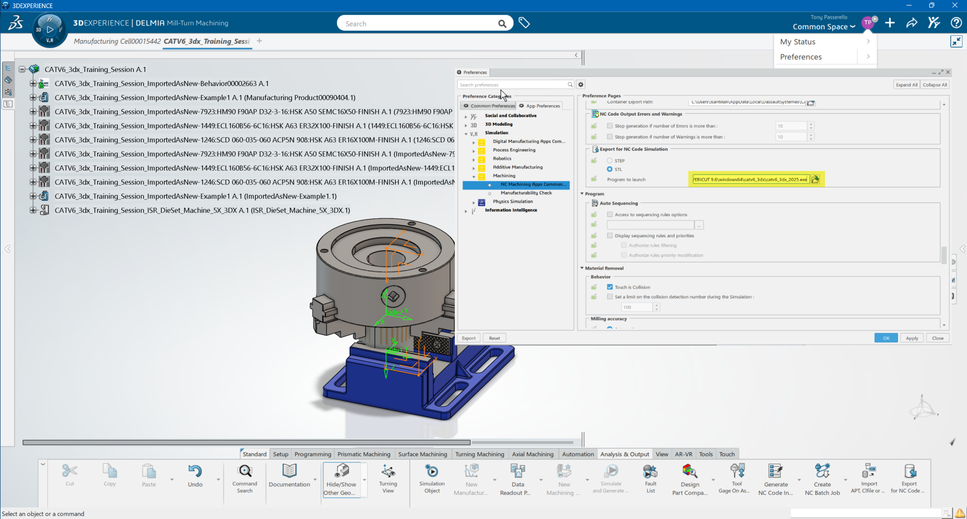
How set up the 3DEXPERIENCE External NC Code Simulation (Connector) icon: CATV6_3dx Interface
1. Select Preferences > App Preferences > NC Machine Apps Common... > Export for NC Code Simulation
2. Set the desire model format STL or STEP
3. Browse the CATV6_3dx batch file:
"C:\Program Files\CGTech\VERICUT x.x.x\windows64\commands\catv6_3dx_2025.bat"
How to add an icon to the 3DEXPERIENCE Toolbar: CATV6_3dx Interface
![]()
1. Copy the icon file from the Vericut installation path to where 3DEXPERIENCE expects to find it. The paths depend on where you have 3DEXPERIENCE installed, but typically you will find a large folder under:
C:\Program Files\Dassault Systemes\B424_Cloud\win_b64\resources\graphic\icons
Copy from:
2. Get 3DEXPERIENCE running.
3. Open a Manufacturing file
4. Pick Tools > Macro 
5. In the Macros dialog, pick Macro Libraries.
6. In the Macro Libraries dialog, set the Library type to PLM Directories.
7. Pick Create new library from files and select the folder containing the CATV6.CATScript file. (For example, C:\Program Files\CGTech\Vericut xxx\windows64\catv6_3dx).
8. Close the Macro Libraries dialog.
9. Close the Macros dialog.
10. Pick Tools > Action Bar Customization, then right click in the Menu Bar and pick Add Commands…
11. In the Customize dialog, ensure the Commands tab is to the front.
12. Select Macros from the left-hand list of Categories.
13. Pick CATV.CATScript from the right-hand list of Commands.
14. Click on the Show Properties... button.
15. Pick the ... button to the right of the Icon: label.
16. In the Icon Browser dialog, set the filter to i_catv, then pick Vericut Icon ![]() and Close the Icon Browser.
and Close the Icon Browser.
17. Back on the Customize dialog, position the mouse cursor over the name of the macro, CATV6.CATScript, in the right-hand list, depress the left mouse button, and drag the cursor to the toolbar where you want the icon to appear. It's counterintuitive, but you drag the macro name, not the icon! Repeat this step if you want the icon to appear on more than one toolbar.
18. Close the Customize dialog.
19. From the toolbar, right click and pick Exit Customize Mode
Microsoft Redistributables: CATV6_3dx Interface
The 3DEXPERIENCE-to-Vericut Interface (CATV6_3dx) may require the installation of Microsoft Redistributables, specifically the Windows C++ run-time libraries. These libraries ensure compatibility and proper functioning of the interface, allowing seamless data transfer between 3DEXPERIENCE and Vericut for manufacturing simulation.
Note: A runtime library is a collection of low-level compiler support routines and functions that are used by virtually all programs compiled with GCC (GNU Compiler Collection) and can be downloaded here.
Documentation: CATV6_3dx Interface
Overview: The CATV6_3dx interface exports manufacturing data from 3DEXPERIENCE to Vericut, ensuring a seamless transition for simulation. It automatically configures the necessary Vericut setup requirements and launches the simulation, ready to play.
Vericut Simulation Setup Requirements: To run a successful simulation in Vericut, the following steps must be completed:
1. Select a VMC (Vericut Machine Configuration) – Define the machine setup for simulation.
2. Select and Orient Stock, Fixture, and Design Models – Ensure correct positioning of components.
3. Select NC Programs & Subroutines – Load the necessary machining programs.
4. Define Cutting Tools – Specify the tools used in the machining process.
5. Define Work Offsets Tables – Configure coordinate systems for accurate machining.
Accessing the 3DEXPERIENCE-to-Vericut Interface
To connect 3DEXPERIENCE with Vericut, follow these steps:
1. Select Export for NC Code...

2. Alternately, Run the CATV6_3dx batch file - Navigate to: C:\Program Files\CGTech\Vericut x.x.x\windows64\commands\catv6_3dx_20xx.bat - Execute the file to initiate the interface.
3. Alternately, you can use the Vericut Icon - Click on the Vericut icon to launch the interface.
Important Note: The CATV6_3dx interface requires an active NC Manufacturing file to function properly with Vericut. If the CATV6_3dx Interface is launched and 3DEXPERIENCE is not running, The CATV6_3dx Interface will ask if you wish to start 3DEXPERIENCE.
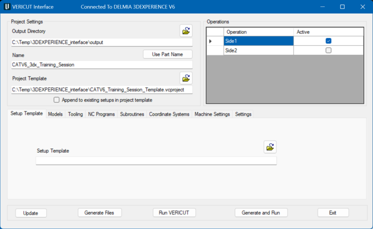
When you trigger CATV6_3dx, you should see a window similar to this:
Note: The Interface Checks Out a license when the Interface is opened and then the Interface Checks In the license when the Interface is closed
Project Settings

CATV6_3dx will generate several files to pass 3DEXPERIENCE/DELMIA information to Vericut. For verification or simulation of one PPR context, the following can be created; - Vericut template file (.VcTmp) - Vericut Tool libraries (.tls) - Vericut Operation file (.ops) - Model files (.stl and *.ply)
The Output Directory specifies the directory where you want the Vericut files to be written (.VcTemp, .tls, .ops, .ply, .stl). Type the Output Directory, or use the "Browse" button to display a file selection window to select the path. The Name specifies the "base" name for all Vericut files that will be created
The files generated by CATV6_3dx are intended to be "add-ons" for existing Vericut projects that contain much more detail than is present in a PPR context. For example, you may have a machine and control fully specified in a project file, and simply wish to place the PPR stock and fixtures on this machine before verifying the new NC programs. In this field you can specify the Project Template file. Type the Project Template, or use the "Browse" button to display a file selection window to select the Vericut project template.
If you wish to append the part operations from a PPR context to the setups that are already defined in your project template, you can click on the Append to existing setups in project template check-box under the template field. Otherwise, and more typically, the imported part operations will be the only setups in the generated project.
Operations
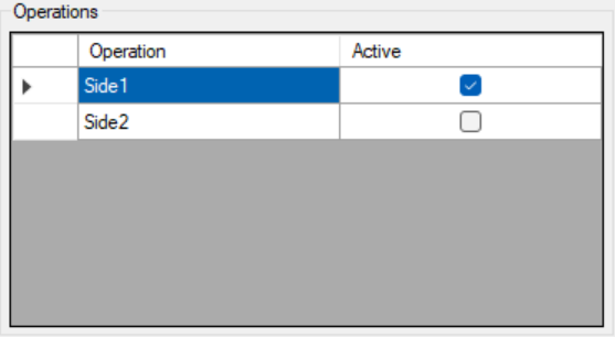
This list contains the names of all the part Operations found in the PPR context. Typically, you would leave each Operation active so that they will all be simulated, but you could cause any of them to be skipped by unchecking their Active check box. When you select an Operation, most of the other elements of the interface will change to reflect the choices made for that Operation.
Setup Template
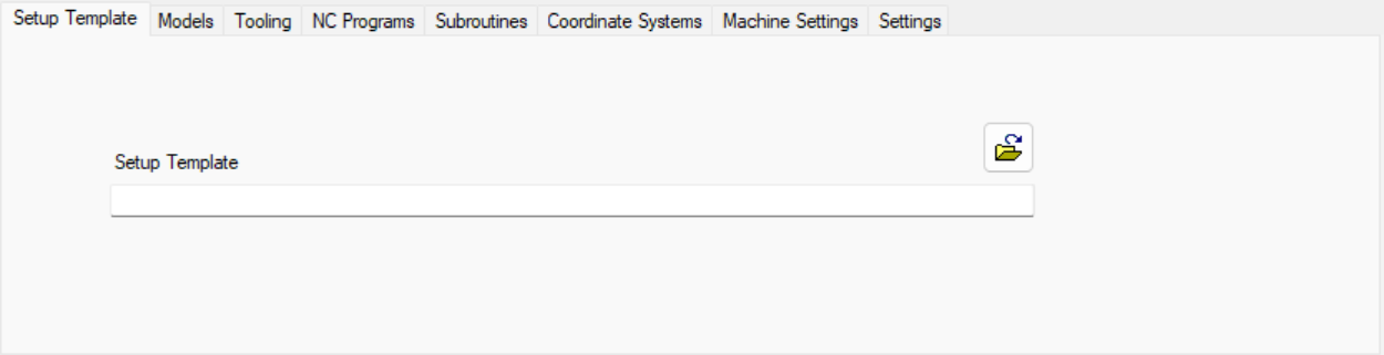
If all part operations in the PPR context use the same machine, and that machine is defined in the Project Template file, then the Setup Template field can be left blank. If there are several machines involved, you will need to have a Vericut project file for each one, and will specify which file each setup should use in this field.
Models
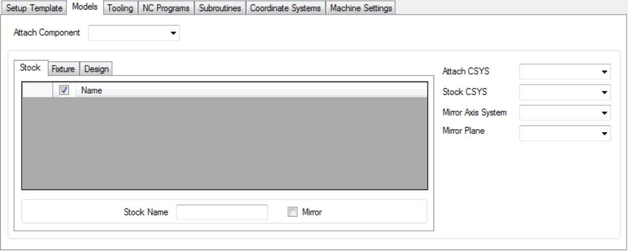
The attach components are read from the machine file that is specified in the project template (or from the machine file specified in the setup template if defined) and presented in a pulldown list called Attach Component.
Each attach component is automatically populated with the stock, fixture and design models from the PPR context. The user can prohibit a model from being transferred to Vericut by unchecking the check box next to the model name.
Also, for each attach component an Attach CSYS, Stock CSYS, Fixture Name, Stock Name, Design Name, Mirror Axis System, Mirror Plane and Mirror option can be specified.
Attach CSYS is the 3DEXPERIENCE/DELMIA coordinate system that is associated with the Vericut Attach Component. If Stock CSYS is specified, then the relationship between the Attach CSYS and the Stock CSYS is used for transitioning between Vericut setups, else the relationship between the current Attach CSYS and the Attach CSYS from the first operation is used.
Fixture Name, Stock Name and Design Name. For each setup you should specify the names of the components in Vericut in which the design, stock and fixture models will be placed. Default component names are simply "Design", "Stock" and "Fixture" or their localized equivalents.
Notes on Attach Components and Model Transfer
Attach Components
- The attach components are read from the machine file specified in the project template.
- If a setup template is defined, the attach components are read from the machine file specified in the setup template.
- These components are presented in a pulldown list called Attach Component.
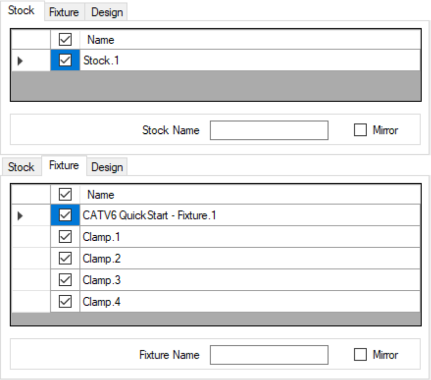
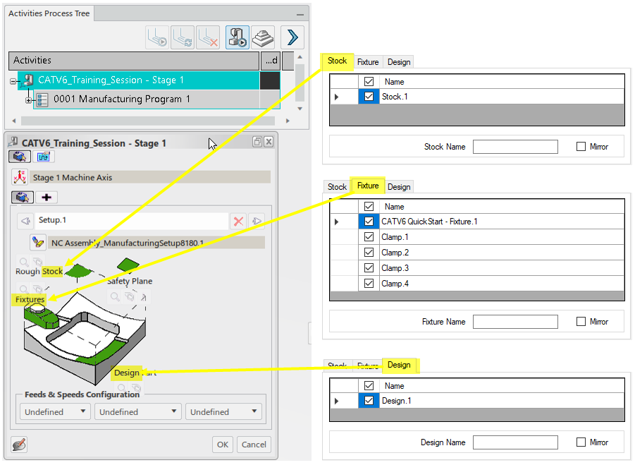
Model Transfer to Vericut
- Each attach component is automatically populated with:
- Stock models
- Fixture models
- Design models
This population is based on the information provided in:
- PPR context > Activities Process Tree > Setup
- Users can prohibit a model from being transferred to Vericut by unchecking the checkbox next to the model name.
Note: for each Attach component an Attach CSYS, Stock CSYS, Fixture Name, Stock Name, Design Name, Mirror Axis System, Mirror Plane and Mirror option can be specified.
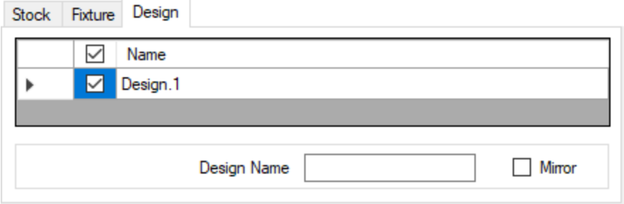
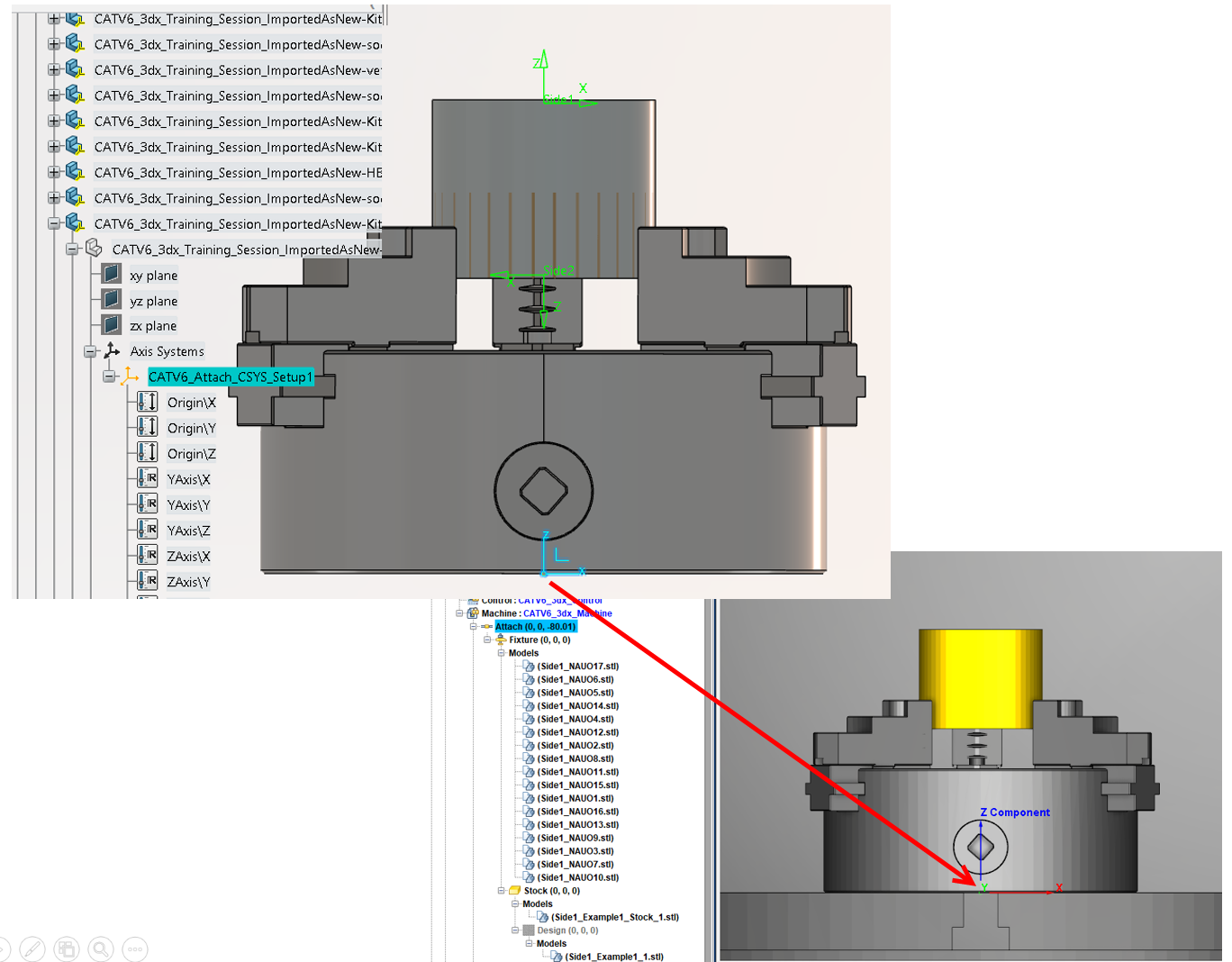
Notes on Attach CSYS and Model Naming in Vericut
Attach CSYS is the 3DEXPERIENCE coordinate system that is associated with the Vericut Attach Component. If Stock CSYS is specified, then the relationship between the Attach CSYS and the Stock CSYS is used for transitioning between Vericut setups, else the relationship between the current Attach CSYS and the Attach CSYS from the first operation is used.
By default, the fixture, stock and design components will be named “Fixture,” “Stock,” and “Design” in Vericut. These defaults can be overridden by specifying a fixture, stock or design name.
Notice in the below image, that in 3DEXPERIENCE the CATV6_Attach_CSYS_Setup1 coordinate system is positioned to align with the Vericut Attach component.
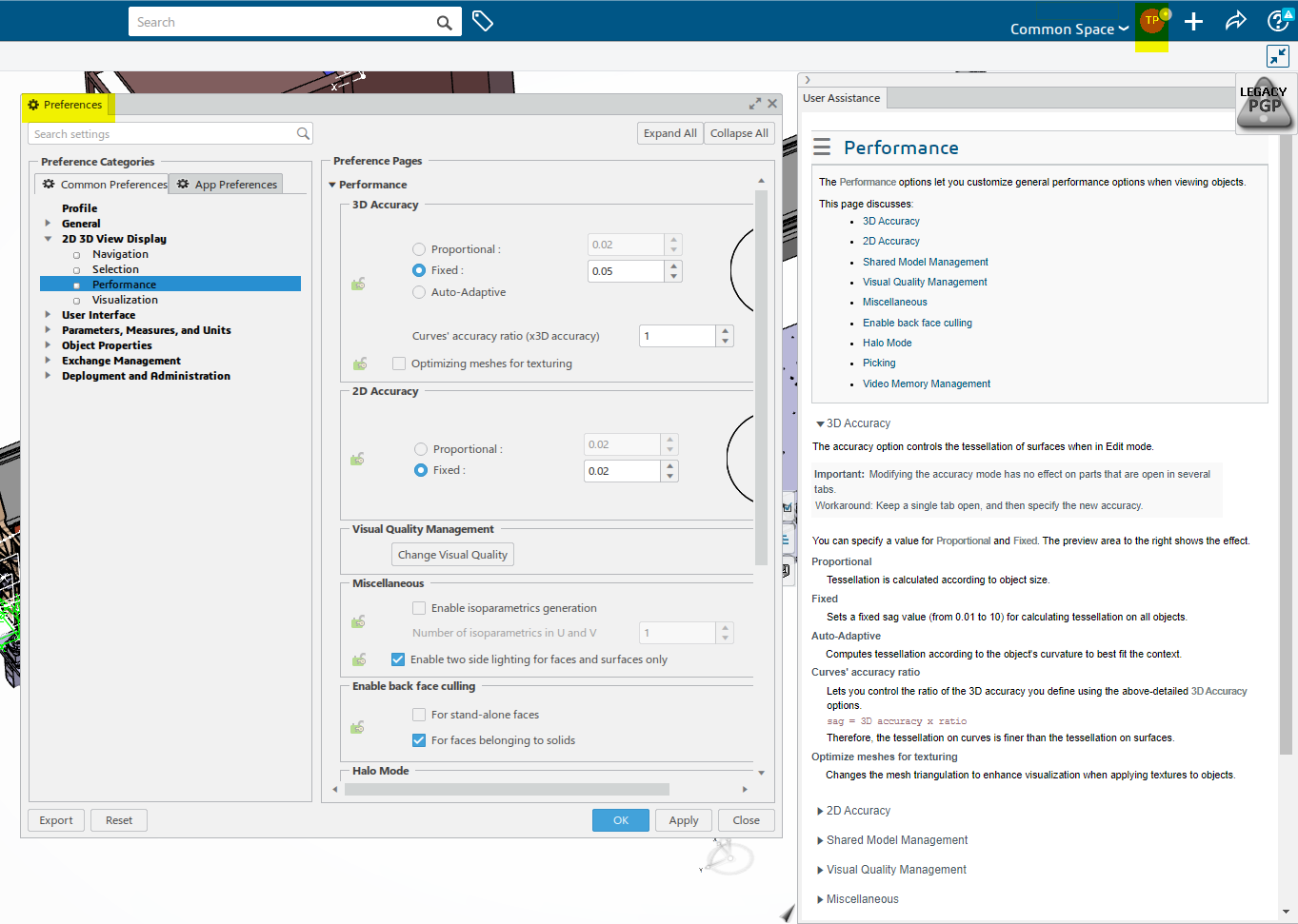
3DEXPERIENCE model output tolerance
Curently CATV6_3dx does not have a Model chordal deviation option. To have CATV6_3dx adjust the Model chordal deviation, a user needs to set the 3D Accuracy accordingly.
The 3D Accuracy option controls the tessellation of surfaces when in Edit mode."Tessellation" means that the surfaces of your geometry are built using triangles. A triangulation is computed to describe the neighborhood relation of all points.
- To activate Edit mode, do one of the following:
- Double-click a 3D part or a 3D shape from the tree.
- From the Tools section of the action bar, click Switch to Edit Mode.
3D Accuracy Menu access
- 3DEXPERIENCE > Preferences
- 2D 3D View Display > Performance > 3D Accuracy
Tooling
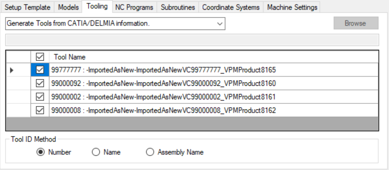
Select one of the following options from the pull-down list: - Generate Tools from 3DEXPERIENCE/DELMIA information Choose this option to have 3DEXPERIENCE /DELMIA create a tool library using the tool data in 3DEXPERIENCE/DELMIA. - Use Selected Tool Library Choose this option to specify a specific tool library to use. Enter the \path\filename of the tool library file in the text field or use the Browse button to display a file selection window and use it to specify the \path\filename of the tool library file. - Use Tools from the Setup Template Choose this option to use the tool library file stored in the Setup Template instead of one created by CATV6_3dx. - Merge Tools into Setup Template Tool Library Choose this option to merge the tool library created by CATV6_3dx, with the tool library file stored in the Setup Template, and use the "merged" tool library rather than one created by CATV6_3dx.
If Use Selected Tool Library is selected, then type the tool library name in the text field or use the "Browse" button to display a file selection window to select the tool library file.
The tool list allows the user to transfer a tool’s NOCUT User Representations to Vericut. If a tool’s check box is checked, then the NOCUT User Representations for the tool will be used. If the tool’s check box is unchecked, then the parametric holder for the tool will be used.
Use Tool ID Method to define how the tool IDs are generated. Typically, Number and Name are used for milling and Assembly Name is used for turning.
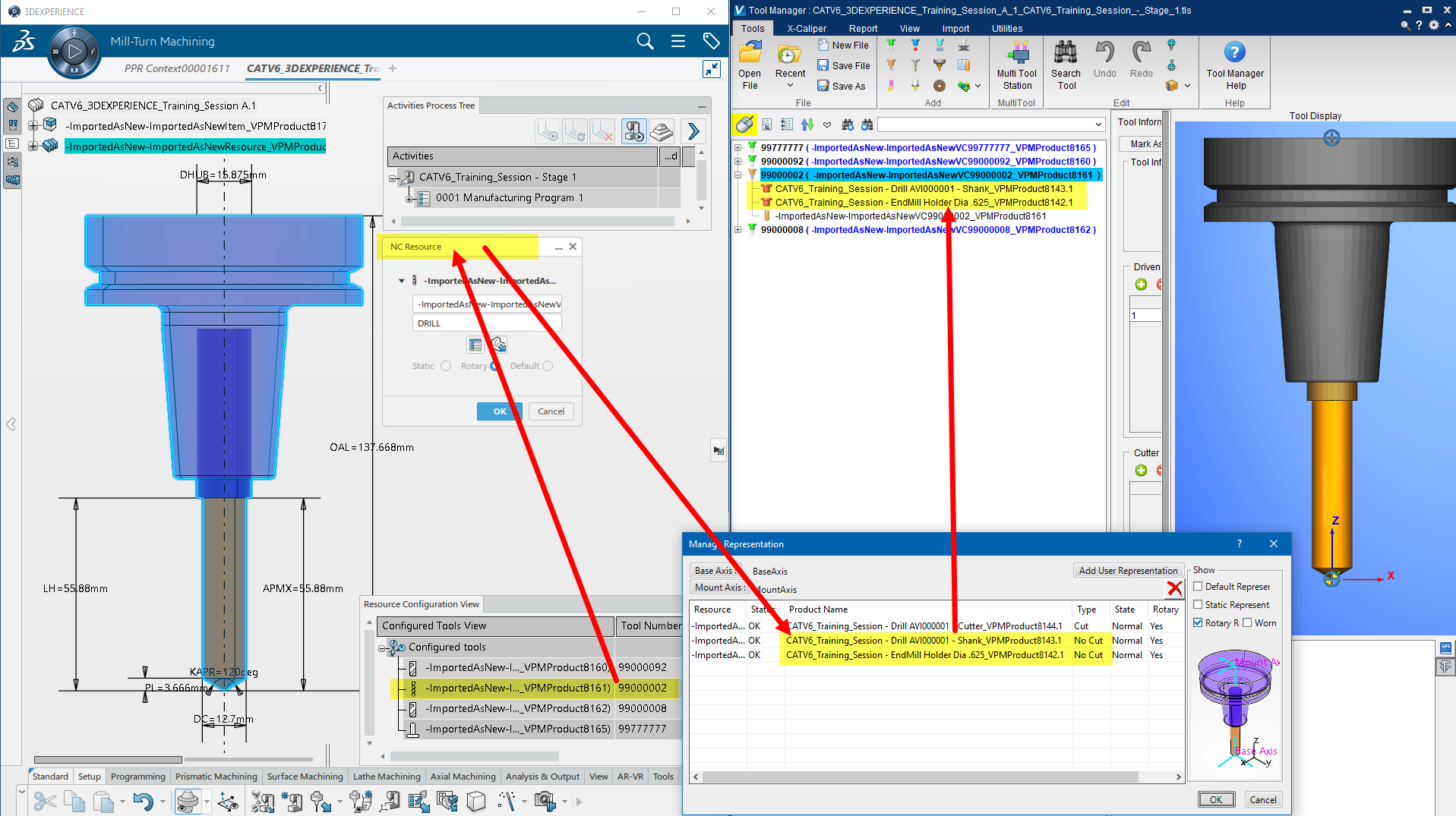
User Representation Notes
Below is an image to illustrate how the CATV6_3dx Interface handles User Representations.
NC Programs
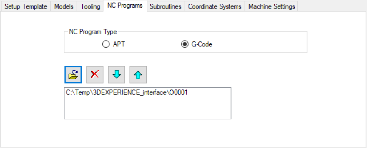
Specify whether the NC programs to be passed to Vericut are APT or G-Code. Use the Add button to browse for and add a tool path to the list. Use the Delete button to delete a tool path from the list. It is important to ensure that the list is in the order of cutting.
Subroutines
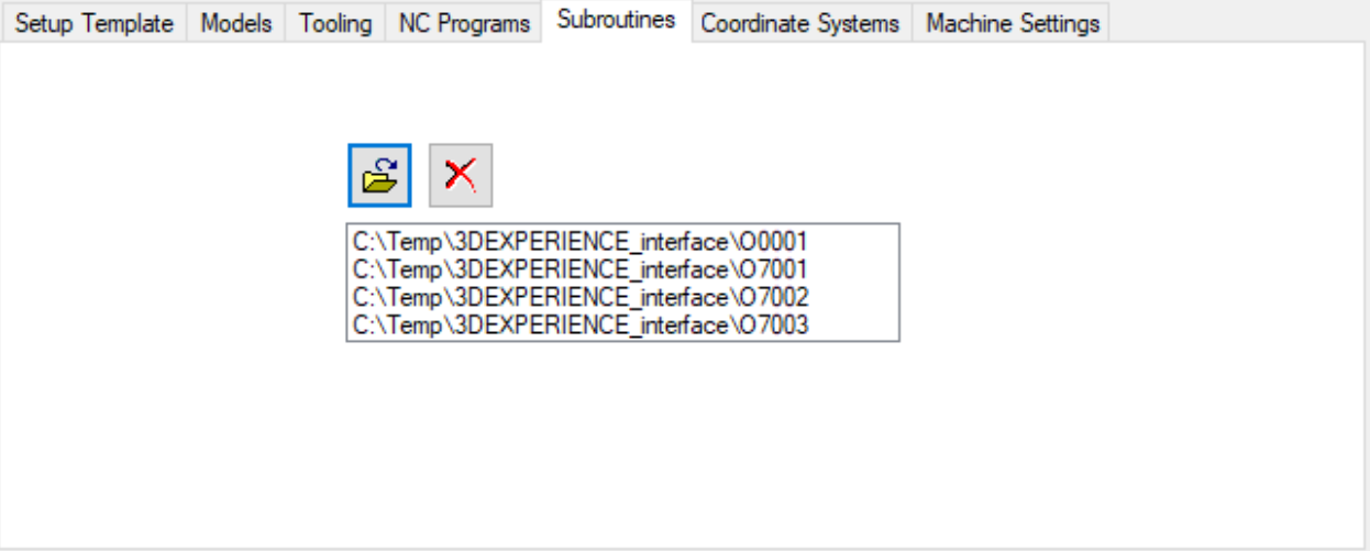
If you have G-Code programs that reference subroutines, you can use the Add button to browse for and add subroutine files to the list. Use the Delete button to delete subroutine files from the list.
Coordinate Systems
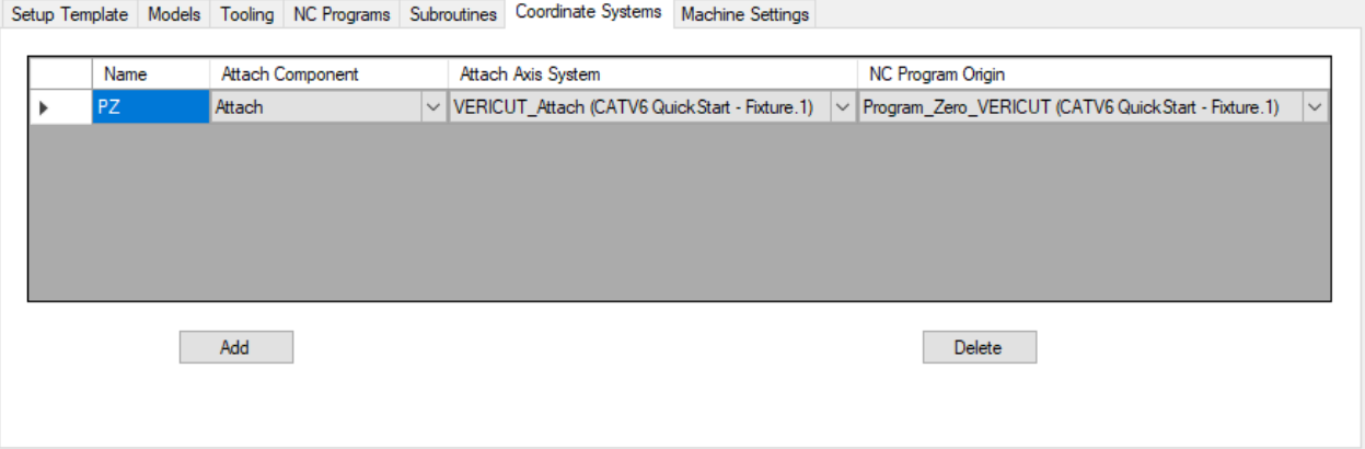
The Coordinate Systems list allows for the definition of a coordinate system that defines the relationship between an Attach Axis System and the NC Program Origin.
Use the Add button to create a new coordinate system.
A default coordinate system Name is assigned when created and can be changed and must be unique.
The Attach Component is the Vericut component in which the coordinate system will be attached to. The Attach Axis System and the NC Program Origin are 3DEXPERIENCE Axis Systems of the current PPR. Use the Delete button to delete a coordinate system.
Machine Settings
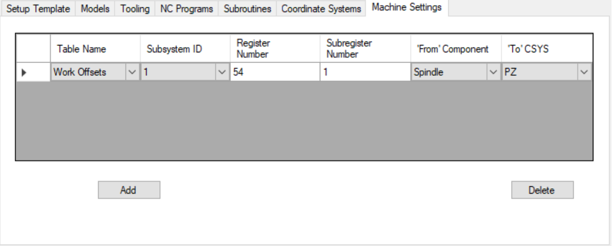
The Machine Settings list allows for the definition of work offsets which defines the relationship between the ‘From’ Component and the ‘To’ CSYS.
Use the Add button to create a new work offset record.
Table name can be Program Zero, Work Offsets, or Base Work Offset.
Set the appropriate Subsystem ID, Register Number and Subregister Number. The ‘From’ Component is a Vericut component. The ‘To’ CSYS is a coordinate system defined in the Coordinate Systems list.
Settings
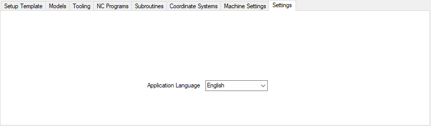
The Application Language list allows for the selection of a native language.
Available Languages:
US English, French, German, Italian, Portuguese, Chinese, and Japanese.
Generate buttons

CATV6_3dx is not aware when you switch between PPR contexts. The Update button forces CATV6_3dx to refresh the interface content from the currently active PPR. If a PPR context does not exist in the current session of 3DEXPERIENCE/DELMIA, then the program will display a warning message.
When you have provided CATV6_3dx with all the information it needs, you can perform the transfer of data to, and triggering of, Vericut. Click on the "Generate files" button to create the tool libraries, models and NC programs without triggering Vericut. Once you have all the files needed, you can fire up Vericut with the "Run Vericut" button.
You can perform both of these steps at once with the "Generate and Run" button. The "Exit" button terminates the program.
Preferences
Also known as ‘prefs’ file, stores all user specified ‘global’ settings for interface operation. The settings stored are called ‘global’ because they are responsible for overall look & feel and operational behavior of the interface. They are not tied to any specific 3dx project. By default, ‘Preferences’ file is generated at C:\Users\username\catv6_3dx_user.prefs
Custom Data
CATV6_3dx uses a custom data file to store all user settings. The name of the custom data file is the active 3DEXPERIENCE/DELMIA PPR name with the extension ".CatvCustomData." The custom data file is written to the C:\Users\username\AppData\Roaming\CGTech\catv6_3dx_version directory. The custom data file is read when CATV6_3dx is launched and written when CATV6_3dx is exited.
DS XML API transaction log
CATV6_3dx uses a DS XML API to output 3D models and the data exported is saved to a transaction log file. The name of the transaction log file is the active 3DEXPERIENCE/DELMIA PPR name with the extension ".xml". The transaction log file is written to the C:\Users\username\AppData\Roaming\CGTech\catv6_3dx_version directory.