840D Virtual NC Kernel and Interface (VNCK)
Introduction 840D Virtual NC Kernel and Interface
The 840D Virtual NC Kernel (VNCK) and Interface is a Vericut optional module that provides an alternate control emulation method using the VNCK program developed by Siemens Automation and Drives Motion Control Systems Division, the developers of the 840D CNC control. When Vericut uses the VNCK for simulation, Vericut is not reading the NC program and is not calculating the machine's axes positions. Rather, the VNCK (an external process running on the Windows computer that is also running Vericut) reads the NC program, calculates the axes positions, and sends those positions to Vericut. The VNCK is only able to read and simulate NC programs written for the Siemens 840D control.
The VNCK and Interface consists of two or three components: The 840D VNCK software program developed by Siemens and the Vericut Interface to the VNCK program. The third component could be Siemens HMI interface. Using this optional module, the Vericut simulation is controlled by the VNCK program. The Vericut Interface starts the VNCK and instructs it to load the control configuration data and NC program. During simulation, the VNCK then reads the NC program, calculates the NC motion axes positions, and sends this motion information to Vericut. The VNCK program contains the actual 840D control's NC kernel, providing NC program processing and motion emulation consistent with the physical control. The Vericut interface handles communication between the VNCK and Vericut, using Microsoft's COM protocol.
Limitations:
The Optimization applications ARE NOT compatible with the VNCK. Also, since the VNCK is directing the simulation, other standard Vericut simulation features may not be available or may behave differently. Additionally, the VNCK notifies Vericut when motion commands, those NC lines containing axes motions, are processed. Other NC program lines, such as variable definitions, calculations, and miscellaneous functions, are not considered NC events and are not displayed in the sequential processing of the NC program.
Licensing:
The VNCK program requires a separate node-locked license from Siemens. It is not available as a network license (i.e. does not "float"), but is locked to the specific machine where the VNCK is used. Thus a separate VNCK licensed module is needed for each computer that will run it. The license is locked to the MAC (physical Ethernet hardware) address of ALL network devices detected on the computer. Thus all MAC addresses on the target computer are required.
Vericut Machine/Control Configuration:
A Vericut machine and a control file are still required for a VNCK configuration. When used with Vericut, the VNCK program reads the NC program and passes axes positions to Vericut. However, only axes controlled by the NC kernel (typically the machine's primary motion axes) are recognized. Any other commands, such as tool change, feed rate, palette change, coolant, and other miscellaneous NC program codes are not recognized by the VNCK. These are typically known as "PLC" (Programmable Logic Controller) functions, outside the realm of the NC kernel. It is Vericut's responsibility to emulate these PLC actions. A mechanism is available to register PLC commands with the VNCK, so that it can notify Vericut when one of these commands is encountered. However, Vericut must be configured to register each command and provide a simulation action for the event.
Currently, only Vericut NC macros configured in the Word Address dialogue may be executed. It is not possible to execute a sub-program from within Vericut when using the VNCK control emulation.
NC "ARC" Data:
In addition to the usual Vericut configuration requirements, Vericut must also copy the NC "ARC" (ARChive) data file from the physical 840D control to the simulation computer. This file must then be expanded using Siemens' ARC utility, and configured for VNCK simulation. The ARC file is then saved in a proprietary binary format for use with the VNCK.
SRAM Data:
Compressed format of the NC “ARC” file.
VMF Data:
Similar to the SRAM file, this is a ‘zip’ file that contains several file representing the NCU state. This only works with the Linked mode of VNCK. This file could be produced from an ARC or SRAM file via VNCK View software.
Hardware:
The VNCK only works on computers running Windows 2000 and Windows XP Professional operating systems.
Installation and Use of VNCK
General Description
The Siemens’ Virtual NCK (VNCK) system is used to drive a Vericut simulation by providing the functions of a target Sinumerik 840D control. The VNCK uses the actual 840D machine parameter (ARC) file when processing NC program (MPF) and subroutine (SPF) files. A VNC Server works with the VNCK to control NC program execution and obtain the processed 840D status and axis motion results. Vericut interfaces to this VNC Server and receives the axis positions resulting from NC commands as well as data from the program processing within the VNCK. Vericut uses this VNCK data to simulate stock cutting, machine axis motions, and to keep various status displays updated.
Siemens’ VNCK
Users should follow Siemens’ directions for installing the VNCK and obtaining the necessary operating license. For each machine control being simulated, the user must obtain a Sinumerik 840D ARC (archive) file. The ARC file contains machine parameter setting, axis definitions, NC programs, subprograms, and tool definitions. Since 840D control space is limited, all unnecessary NC programs and tool definitions should be deleted from the 840D control before the ARC file is saved.
Considerable time is normally required to boot the VNCK from an ARC file. However, after the VNCK is booted, the VNCK View utility can save a binary version of the VNCK's memory and use it to quickly boot on subsequent occasions. This binary version of the VNCK's memory is called an SRAM file and is recommended for Vericut applications. Note that all SRAM files should be rebuilt whenever a new version of the VNCK is installed.
HMI
The Human Machine Interface (HMI) is a Siemens product used to monitor and control physical processes involved in industry and infrastructure. User should follow Siemens’ directions for installing the VNCK and obtaining the necessary operating license. According to Siemens documentation, specific versions or HMI are compatible with specific versions of VNCK. User must use HMI-Advanced type with the Linked Mode of VNCK and Vericut. Generally HMI is used to define tool parameters, user parameters, offsets, NC program selection, modifications of cycles and etc. HMI sends and receives data to the VNCK server only. There is no communication with Vericut. Vericut only launches HMI. The “HMI executable” file should be placed in the C:\hmi\mmc2 folder and the following line inserted in the vericut.bat file:
set CGTECH_VNCK_HMI= C:\hmi\mmc2\rngkrnl.exe.
Vericut Implementation
When the VNCK is used with Vericut, the major difference is that Vericut does not read and parse the NC programs. Instead, the VNCK processes the NC programs and provides axis positions to Vericut. Tool change events, messages, alarms, M-codes, and speed-feed settings are also provided to Vericut by the VNCK. Vericut still requires a control file (CTL), but it is only used to process macros associated with the tool changes, M-codes, or speeds and feeds.
The initial implementation does not support Vericut sub-systems or control file subroutines.
The Vericut-VNCK system is distributed with Vericut as a special DLL. The "cgtvnck.dll" file should be placed in the C:\Vericutxx\windows\vericut (where xx is the Vericut version number) folder and the following line inserted in the vericut.bat file:
set CGTECH_VNCKAPI=C:\Vericutxx\windows\vericut\cgtvnck.dll
(where xx is the Vericut version number)
A special file folder structure is also used by Vericut-VNCK applications. The Siemens’ 840D expects a KONFIG.DIR folder containing the machine's definition (ARC and SRAM files) and any subroutine (SPF) files shared by multiple projects. Multiple project folders (e.g. PROJECT_1.WPD, PROJECT_2.WPD) can be defined at the same level as the KONFIG.DIR folder. Each Working Project Directory (WPD) contains the main part programs and associated subprograms (MPF and SPF files).
In Vericut, the VNCK option is selected by setting the "NC Program Type" to "Siemens VNC 840D". The following dialog will appear if Vericut has a license for the VNCK interface:
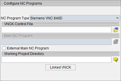
NC Program Type — Type of NC program file for Vericut to simulate.
Initial Tool — When active, Vericut loads an initial tool from a Tool Library file. This action occurs automatically when the Project file is loaded, the NC program is rewound, or the model is reset. Choose the ID of desired tool using the option list next to this feature. This feature is useful when simulating NC programs for machines that have a tool loaded at the time tool processing is started, therefore do not have information about the first tool.
VNCK Control File — Selects a DAT, ARC or INI file from the konfig.dir folder associated with the machine and project being simulated. As described above, a SRAM (.dat) file is recommended, however ARC and INI files can also be directly used.
Single VNCK mode (default)
VNCK Control File — Selects a DAT, ARC, or INI file from the knofig.dir folder associated with the machine and project being simulated. As described above, a SRAM (.dat) file is recommended for regular mode, however ARC and INI files can also be directly used. In Linked mode, user must use a VMF file.
Main Toolpath (MPF) — Selects the NC program being simulated. The main program must have an "mpf" extension and should reside in the "project.wpd" folder if it is not an external MPF.
External MPF — Indicates the MPF does not reside in the WPD folder. The 840D has additional restrictions regarding "external files" defined in Siemens’ documentation.
Working Project Directory — Select the WPD folder for the application being simulated. Note that this folder must have a ".wpd" appended to its name and must have the same parent folder as the "konfig.dir" folder.
Stop VNCK — This button will kill the VNCK process. It should only be used if communications between Vericut and the VNCK is lost.
The VNCK is booted the first time PLAY or SINGLE-STEP is requested in Vericut. Normally there is a several second delay before control returns to Vericut. The status of the boot operation is displayed in the Vericut logger.
The RESET operation in Vericut initializes the system for a new simulation. During a RESET, the VNCK is shut down and rebooted to reset its memory to the initial state. This typically adds several seconds to the normal Vericut RESET operation.
Vericut tool definitions and offset registers are passed to the VNCK during the VNCK boot phase. This information is written to a "VericutVNCK.ini" file residing in the "konfig.dir" folder. All tools including any compensation values (D2, D3, etc.) used in the MPF must be defined in Vericut's tool manager before starting a VNCK simulation. The VNCK will generate an alarm if a tool is not defined when referenced in the MPF. Future versions of the VNCK will allow direct interface calls to replace the need for the VericutVNCK.ini file.
VNCK messages and alarms are displayed in the logger and written to the Vericut log file. In addition, interactions between Vericut and the VNCK can be recorded in the G-Code log file. This trace information is recorded when the "Debug Marco Arguments" option is selected.
During simulation, a "Single Step" request in Vericut might result in several blocks of the NC program being processed. This is because the VNCK reports motion, tool change, and M-code events, but does not report all program blocks being processed. Non-motion blocks (variable assignments, conditional statements, subroutine calls, etc.) may be combined into a single step before results are reported to Vericut.
During a VNCK simulation the Vericut Toolpath window shows a pointer to the current block of the MPF being processed. When subroutines are called, the Toolpath window will only display the SPF file if it has been declared as a subroutine in G-Code Settings (ref. Machine/Control tab > Control Advanced Options > Subroutines tab in the Vericut Help section, in the Vericut Help Library).
Linked VNCK mode
Linked mode of VNCK uses a combination of Vericut VNCK Machine Control Panel (VMCP) and HMI advanced.
VNCK Control File — Selects a VMF file from the knofig.dir folder associated with the machine and project being simulated.
Main Toolpath (MPF) — In Linked Mode the NC program is de-sensitized. NC program selection should be done in HMI.
Working Project Directory — Select the WPD folder for the application being simulated. Note that this folder must have a “.wpd” file name and must have the same parent folder as the “konfig.dir” folder. During the booting, VMCP sends a project folder to VNCK. All the MPF and SPF files in the “.wpd” folder should appear in HMI under folder “VNC_SIM.”
Linked VNCK button launches the VMCP panel.
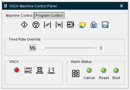
VNCK Machine Control Panel (VMCP) — Panel controls the VNCK server and the Vericut simulation. VMCP uses the selected VMF file defined in the VNCK Control File area. Boot button should be the first selection and after several seconds, the user needs to launch HMI. While this panel is open, the regular Vericut VCR buttons disappear and show the “Stop VNCK” button.
Machine Control tab
Program Start — Sends an event to VNCK server to start the program.
Stop Program — Sends an event to VNCK server to stop the program.
Reset Program — Sends an event to VNCK server to reset the program.
Bag Reset — Sends an event to VNCK server to perform a BAG reset.
Single Step — Sets the simulation to Single Mode. The Program Start button is then used to run the simulation.
Reset Material — This only resets Vericut. Re-applies the removed material on stocks.
Reset Kernel — Removes mounted tools, resets Vericut and VNCK variables, and moves the virtual machine at initial position.
Save VMF file — Saves a VMF file if necessary after modification of the VNCK Control file.
Feed Rate Override
Feed Rate Override — Sets Feed Rate Override mode. Slider bar is used to set the value of the override as a percentage.
VNCK
Boot Button — Sets the simulation to Dry Run mode.
Launch HMI — Launches HMI.
Machine — HMI panel updates to different menu. This is the same functionality as pressing the F10 key on your keyboard.
Channel — HMI panel switches to a different machine channel. This is the same functionality as pressing the F11 key on your keyboard.
Program Control tab
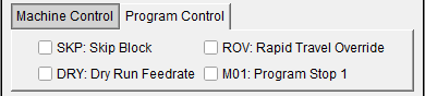
SKP — Sets simulation to Skip Block.
Dry — Sets the simulation to Dry Run mode.
ROV — Sets simulation Rapid Travel Override (Rapid Travel Override value is defined in the preset file).
M01 — Sets simulation to stop at M01.
Preset Files
To initialize VNCK to a user preferred status. The current possibilities are set STOP at M1 and set Rapid Override value. Those feature could define in a text file and the following line inserted in the vericut.bat file:
set CGTECH_VMCP_PRESETS=C: %CGTECH_PRODUCTS%\presets.txt
Format of the preset file:
VmcpM1,1
VmcpRapidOverride,100
Alarms Status
There are two types of alarm events: Alarm Event and Alarm Description. The Alarm Event only has the alarm type: Cancel, Reset, or Boot. The Cancel alarm event can be canceled in the code. The Reset and Boot alarms cannot be canceled in the code and VNCK must be rebooted by the user. The indicator lights can be green, yellow, or red. Green indicates that there are no alarms. Yellow indicates that the alarm is minor. Red indicates that the alarm is severe. Alarm Descriptions do not affect the indicator lights.
In Linked mode, Vericut tool definitions and offset registers are NOT passed to the VNCK during the VNCK boot phase. But this information is written to a "VericutVNCK.ini" file residing in the "konfig.dir" folder. The user would have the possibility to use it.
The user must use HMI to select NC program. According the VMF file, the user would have to define tool definitions and offset registers in HMI.
Stop VNCK — This button will kill the VNCK process. It should only be used if communications between Vericut and the VNCK is lost.
Other
Most VNCK alarms need to be resolved before simulation can be completed. The Siemens’ diagnostic document "840d_da.pdf" provides additional problem descriptions which may be helpful resolving alarms. The VNCK error identification is displayed in the logger window and can be used with the "840d_da.pdf" to obtain the complete error description.
During a VNCK simulation the Vericut dialog for variables (ref. Project tab > Project group > Variables in the Vericut Help section, in the Vericut Help Library) will display updated values for Tracking Variables. Note that the VNCK reports variable values when they are processed in the "Preparatory" phase. Since the Preparatory phase may be several blocks ahead of the current motion block, the values may change before the toolpath window indicates the block has been processed. VNCK notifies Vericut when there is M-Code , it is possible to update/modify Siemens variables with the Vericut G-Code Processing. Also see the restriction below for variables.
The VNCK calculates the time during a simulation and this time value is used to update the Vericut status information.
Vericut Control Files
The Vericut CTL file is used to process tool change events, M-codes, and speed-feed settings. The initial implementation does not support Vericut sub-systems and control file subroutines. Two special CTL words have been used to handle tool selection and tool changes. These are "VNCK_TOOLSELECT" and "VNCK_TOOLCHANGE". The CTL file must be modified to define these words and associate the correct macros with them for Vericut tool changes.
During a VNCK boot and VMCP Reset kernel the Vericut dialog for Control variables (ref. Machine / Control tab > Control group > Control Variables in the Vericut Help section, in the Vericut Help Library) will update values for VNCK initialization.
Machine File Changes
The machine tool builder chooses names for the axes defined in the 840D ARC file. During the VNCK boot phase, the VNCK provides these configuration names to Vericut so they can be matched with Vericut axes components. The Vericut components should be renamed to agree with the ARC file names.
If the axes names are not known, they can be located in the ARC file by searching for definitions similar to those shown below:
N10000 $MN_AXCONF_MACHAX_NAME_TAB[0]="X1"
N10000 $MN_AXCONF_MACHAX_NAME_TAB[1]="Y1"
N10000 $MN_AXCONF_MACHAX_NAME_TAB[2]="Z1"
N10000 $MN_AXCONF_MACHAX_NAME_TAB[3]="B1"
N10000 $MN_AXCONF_MACHAX_NAME_TAB[4]="SP"
Restrictions
- In-Process (IP) files are not operational with the VNCK since the VNCK can not again be synchronized with Vericut when the IP file is later restored. An error message is displayed if a VNCK session attempts to save an IP file.
- The VNCK supports turning applications; however, turning has not been implemented in the initial Vericut-VNCK interface.
- The VNCK supports multiple channels; however, the relation between multiple channels and Vericut sub-systems has not been implemented in the initial Vericut-VNCK interface.
- In single mode, during the VNCK boot process, all MPF and SPF files in the WPD folder are loaded into the VNCK's memory. Large programs may overflow the available VNCK memory producing a "NC Memory Full" alarm and truncating the file. If this occurs, move the files to a separate folder and check the "External MPF" box on the Toolpath dialog.
- During simulation, Vericut and the VNCK exchange asynchronous messages. Errors have occurred causing the Vericut to lose its connection with the VNC Server. Vericut will wait for 30 seconds before admitting a failure. Report this problem and restart your job.
- Optimization is not supported in the Vericut-VNCK system. These options require the original tool path file which is not being read and parsed by Vericut when the VNCK is active.
- The number of variables being watched is limited to 5 with VNCK version 1.40.10.0. This limitation should be removed in future versions of the VNCK.