ESPRIT TNG/Edge-to-Vericut Interface (ETNGV)
Overview
ETNGV is an interface that facilitates the transfer of Fixture, Stock, Design, and 3D tool representations from the ESPRIT TNG/EDGE manufacturing process to Vericut.
Software Requirements: ESPRIT TNG/Edge Interface
Licensing Requirements
CGTech Licensing:
Esprit TNG Interface
Installation & Configuration: ESPRIT TNG/EDGE Interface
Using an Installer To install the ESPRIT TNG/EDGE-to-Vericut interface (ETNGV), download the latest Vericut Software Release and run either esprit_tng_interface_install.exe or esprit_edge_interface_install.exe, then follow the step-by-step prompts to complete the installation.
You can download the installer from the Vericut website: Request Latest Vericut Software Release
Enable the interface: ESPRIT TNG/EDGE Interface
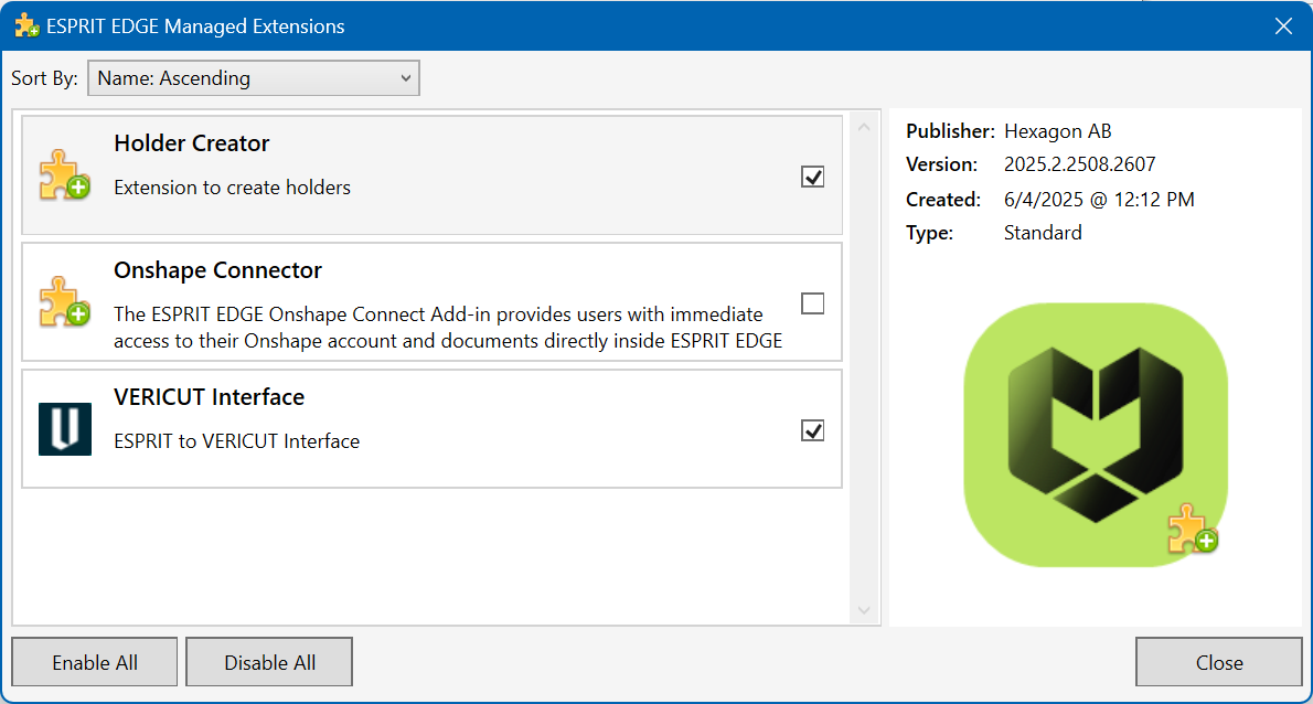
To enable the Vericut extension, select File > Extension and check Vericut Interface
Environment variables: ESPRIT TNG/EDGE Interface
To enable the ESPRIT TNG/EDGE Interface to locate the necessary Vericut files, the following environment variables must be defined:
Environment Variables: Description & Example
CGTECH_INSTALL
Purpose: Defines the Vericut installation folder.
Example: For Vericut 9.7, set to: C:\Program Files\CGTech\Vericut 9.7
CGTECH_PRODUCTS
Purpose: Specifies the folder for the operating system running Vericut (windows64).
Example: For Vericut 9.7, set to:
C:\Program Files\CGTech\Vericut 9.7\windows64
LSHOST
Purpose: Defines the name of the license server computer.
Example: localhost
CGTECH_SINGLE_PLATFORM (Optional)
Purpose: Specifies if Vericut is running on a single platform.
Example: CGTECH_SINGLE_PLATFORM=YES
CGTECH_ETNGV_LANGUAGE (Optional)
Purpose: Allows the interface to use a localized language file instead of US English.
Note: TThe application also provides the option to change the language directly from within the user interface.
Available Languages: French, German, Italian, Portuguese, Chinese, Japanese.
Example:
- ESPRIT TNG
CGTECH_ETNGV_LANGUAGE=C:\USERS\PUBLIC\DOCUMENTS\D.P.TECHNOLOGY\ESPRIT TNG\DATA\EXTENSIONS\Vericut\French
- ESPRIT EDGE
CGTECH_ETNGV_LANGUAGE=C:\Users\Public\Documents\Hexagon\ESPRIT EDGE\Data\Extensions\Vericut\french\
Set up a Vericut icon: ESPRIT TNG/EDGE Interface
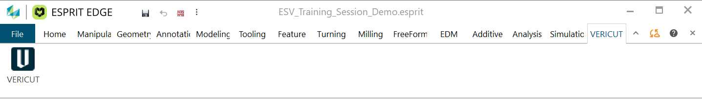
No manual configuration required, once the Vericut extension is activated, the Vericut menu is automatically added to the ESPRIT TNG/EDGE ribbon. This menu includes the Vericut ![]() icon, no additional setup is required.
icon, no additional setup is required.
Microsoft Redistributables: ESPRIT TNG/EDGE Interface
The ESPRIT TNG/EDGE-to-Vericut Interface (ETNGV) may require the installation of Microsoft Redistributables, specifically the Windows C++ run-time libraries. These libraries ensure compatibility and proper functioning of the interface, allowing seamless data transfer between ESPRIT TNG/EDGE and Vericut for manufacturing simulation.
Note: A runtime library is a collection of low-level compiler support routines and functions that are used by virtually all programs compiled with GCC (GNU Compiler Collection) and can be downloaded here.
Documentation: ESPRIT TNG/EDGE Interface
Overview:
The ESPRIT TNG/EDGE interface exports manufacturing data from ESPRIT TNG/EDGE to Vericut, ensuring a seamless transition for simulation. It automatically configures the necessary Vericut setup requirements and launches the simulation, ready to play.
Vericut Simulation Setup Requirements:
To run a successful simulation in Vericut, the following steps must be completed:
1. Select a VMC (Vericut Machine Configuration) – Define the machine setup for simulation.
2. Select and Orient Stock, Fixture, and Design Models – Ensure correct positioning of components.
3. Select NC Programs & Subroutines – Load the necessary machining programs.
4. Define Cutting Tools – Specify the tools used in the machining process.
5. Define Work Offsets Tables – Configure coordinate systems for accurate machining.
Accessing the ESPRIT TNG/EDGE-to-Vericut Interface
To activate the Vericut Interface, select Vericut ![]() icon from the ribbon.
icon from the ribbon.
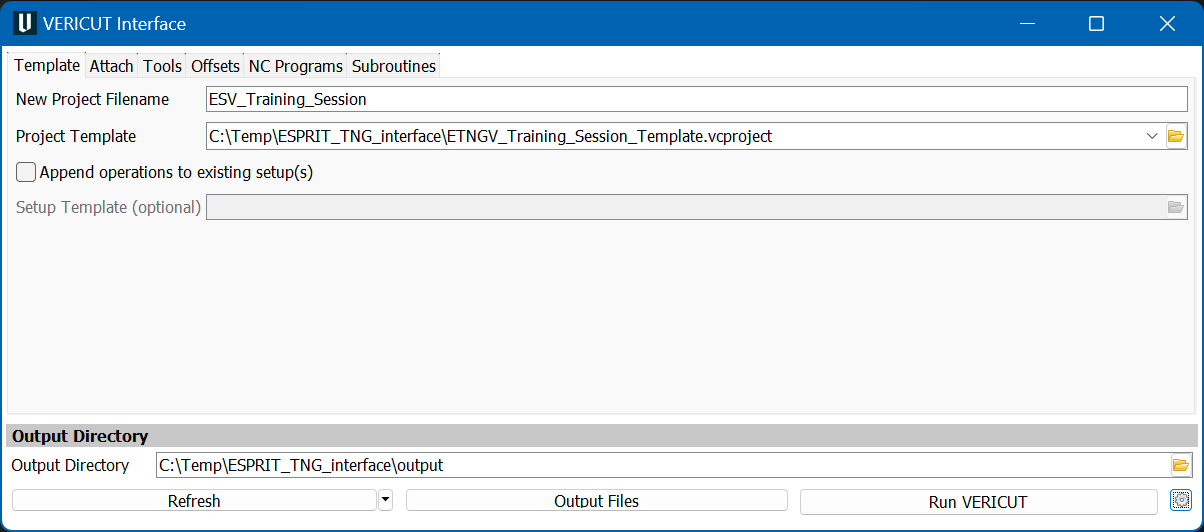
When you trigger ETNGV, you should see a window similar to this:
Important Note:
The ESPRIT TNG/EDGE interface requires an active NC Manufacturing file to function properly with Vericut.
License Handling
- The interface checks out a license when opened.
- The interface checks in the license when closed.
Template
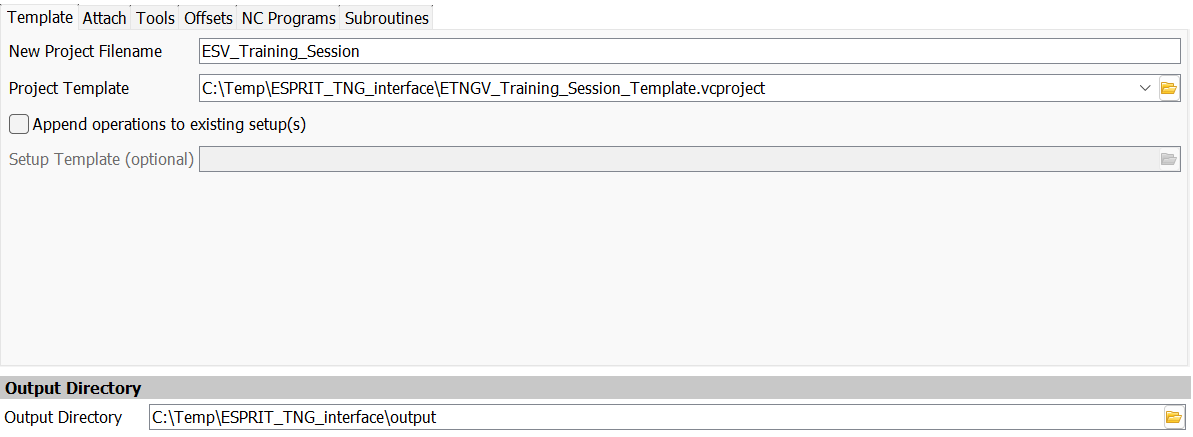
The Template tab is used to specify a file name for the new project, a project template, the output directory that files will be written to, and optionally, a setup template. The New Project Filename and the Project Template fields must be filled in before you can move to another tab.
New Project Filename: Enter the "base" name for Vericut files that will be created. By default, the name of the ESPRIT TNG .esprit file is used.
Project Template: Enter the /path/filename of an existing template file (.VcProject) that you want loaded in the text field or use the  (Browse) icon to display a file selection window and use it to specify the /path/filename.
A template file is a previously defined Vericut project file (.VcProject).
(Browse) icon to display a file selection window and use it to specify the /path/filename.
A template file is a previously defined Vericut project file (.VcProject).
Note: You can Drag and Drop the Vericut Project file into the Project Template field. This feature is also available with the Post Processor file, NC Programs and Subroutines fields
Append operations to existing setup(s): When toggled "on" (checked), the ESPRIT TNG-to-Vericut Interface will append the operations in the ESPRIT TNG part file, to the setups that are already defined in your Project Template file, and setups from both files will be contained in the generated project file. Otherwise, and more typically, the imported ESPRIT TNG part operations will be the only setups in the generated project file.
Note: The Interface only supports 1 Esprit TNG/EDGE Setup at a time.
Setup Template (Optional): Enter the /path/filename of the Setup "template" file that you want loaded in the text field or use the icon to display a file selection window and use it to specify the /path/filename. A setup "template" is a previously defined Vericut project file (.VcProject) containing files and settings required for Vericut simulation. The Setup Template feature is only available when the Append operations to existing setup(s) feature is toggled "on" (checked). The following features are common to all Vericut Interface window tabs.
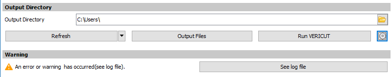
Output Directory: Enter the path in the text field to the directory where you want the Vericut files output or use the icon to display a directory selection window and use it to specify the \path.
NOTE: The Output Directory, Refresh, Output Files, Run Vericut features and the Settings ![]() icon are common to all Vericut Interface window tabs.
icon are common to all Vericut Interface window tabs.
Attach
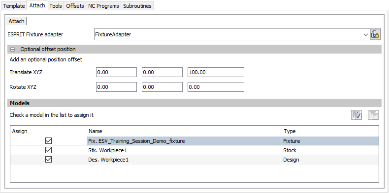
The Attach tab is to specify attach points for Esprit TNG models in Vericut. Attach tabs are be created by parsing through the machine file; there will be a separate tab for each Attach found in the machine file.
Esprit Fixture Adaptor: Use to specify which ESPRIT fixture adaptor maps to which Vericut attach component. The drop-down menu at the top lets user to choose which ESPRIT Fixture adapter maps to which Vericut attach point. The models of fixtures and workpieces (with stock and target part) mounted on the selected fixture adapter appear in the models list.
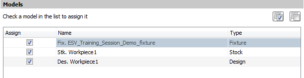
All model names are prefixed by their type: Stk for stocks, Des for designs, and Fix for fixtures. Models can be selected by clicking on the corresponding checkbox in the 'Assign' column. By default, all models are selected. There is no mandatory requirement for selecting models. This step can be skipped and user can move on to next tab, without performing any operation here.
Sub-tabs:
The Vericut Interface window: Attach tab will have a sub-tab for each Attach component found in the specified Project Template file.


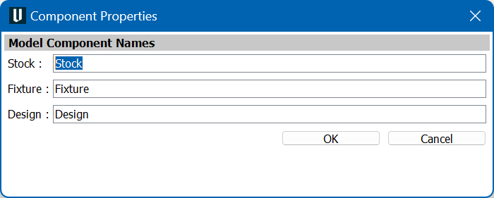
Component Properties
![]() Stock, Fixture and Design model component names can be specified into respective text boxes, if they are preferred to be different then default names.
Stock, Fixture and Design model component names can be specified into respective text boxes, if they are preferred to be different then default names.
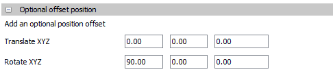
Optional offset position:
Use to add a transformation conversion in case of the mounting point of the Fixture Adaptor in ESPRIT TNG does not match with the Attach point in Vericut. By default, these fields are hidden, if a value is defined in one of these fields, the "Optional offset position" group will be appearing expanded otherwise it will be appearing collapsed.
Models:
the models list contains all models mounted on the fixture adapter selected.
The models of fixtures and workpieces (with stock and target part) mounted on the selected fixture adapter appear in the models list. All models are selected by default. If the user changes the fixture adapter in the Esprit Fixture Adaptor field, the list will be actualized automatically.
Check a model in the list to assign it
![]() Check all models
Check all models
![]() Uncheck all models
Uncheck all models
All model names are prefixed by their type: Stk for stocks, Des for designs, and Fix for fixtures. Models can be selected by clicking on the corresponding checkbox in the 'Assign' column. By default, all models are selected. There is no mandatory requirement for selecting models. This step can be skipped and user can move on to next tab, without performing any operation here.
Tools
The Tools tab is used to specify where your tools will come from.
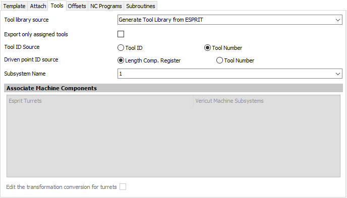
Tool library source Select one of the following options from the pull-down list:
-
Generate Tool Library from ESPRIT: Choose this option to have the ESPRIT TNG-to-Vericut interface create a tool library using the tool data in ESPRIT.
-
Merge ESPRIT Tools with Template Tool Library: Choose this option to merge the tool library created by the ESPRIT TNG-to-Vericut Interface, with the tool library file stored in the Setup Template, and use the "merged" tool library rather than one created by the ESPRIT-to-Vericut Interface.
-
Use Tools from Template Tool Library: Choose this option to use the tool library file stored in the Setup Template instead of one created by the ESPRIT TNG-to- Vericut Interface.
-
Use Existing Tool Library: Choose this option to specify a specific tool library to use. Enter the \path\filename of the tool library file in the Tool Library Name text field or use the Browse button to display a file selection window and use it to specify the \path\filename of the tool library file. If you choose to use this option, you must specify a valid Tool Library before moving to another tab.
Export only assigned tools:
This checkbox is used to specify whether, interface needs to output only the tools which are assigned for manufacturing operations or all the tools specified in the Esprit project.
Tool ID Source:
User can make a choice here between Tool ID and Tool Number specified in Esprit TNG CAM system for specified tool, to become Tool ID in Vericut (to be exported as Tool ID in TLS file). This option will not be visible when user has chosen "Use Existing Tool Library" option on "Tool Generation Scheme" pull-down list explained above.
Driven point ID Source:
User can make a choice here between Length Comp. Register and Tool Number specified in Esprit TNG CAM system for specified Driven Point, to become Length Comp. Register in Vericut (to be exported as Length Comp. Register in TLS file). This option will not be visible when user has chosen "Use Existing Tool Library" option on "Tool Generation Scheme" pull-down list explained above.
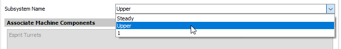
Subsystem Name:
This field is visible if there is a machine head in the TNG document and if there is more than one SubSystem ID in
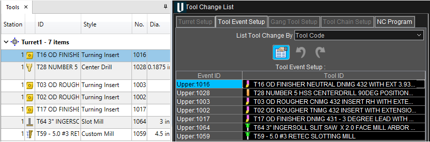
the Vericut template. The Subsystem Name set will be used for the
Vericut Tool Change List Event ID.
The version indicated in variable CGTECH_PRODUCTS will be used to set the version of the tool library file output.
Note: the tls version number priority is to check the Settings first and then if nothing is set within settings, then it will look at what is set within CGTECH_PRODUCTS. This will allow the user the change the tls version output number without having to close the Vericut Interface or Esprit Edge.
Associate Machine Components:
This mechanism is used to map the Esprit TNG turret component with the corresponding Vericut Machine subsystems, listed from specified Vericut machine file. Correct pairings between Esprit turret components and Vericut Machine subsystems help in writing tool-change list.
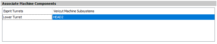
As seen above, there are two columns in the mechanism; all the Esprit TNG Turrets components are listed in first column forming a separate row each. The second column, for each row, is a drop-down menu containing all Subsystems defined inside Vericut machine file. Usern can select any of the Subsystem to make a pair with Esprit TNG turret from second column, in the same row.
Edit the transformation conversion for turrets:
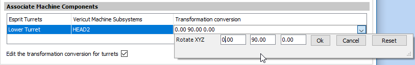
The transformation conversion, third column shows when the "Edit the transformation conversion for turrets' is checked. It is an optional field which may be needed to get the tools on the correct orientation
in Vericut. The orientation convention is a 90 degrees rotation around the Y axis or a 180 degrees rotation around the X axis plus a -90 degrees rotation round Y axis for turrets whose tools need be oriented in the opposite direction.
User defined Esprit TNG Turret- Vericut Subsystem pairings are stored into 'Settings' file.
If no such record found inside 'Settings' file, at the time of loading up the interface, interface will try to automatically assign correct Vericut Machine subsystems to Esprit TNG turret component. For that it will try to look for same name Vericut turret/spindle component name as that Esprit TNG turret, inside Vericut machine file and the subsystem name of that Vericut turret/spindle component will be used to form a pair with Esprit TNG turret on the interface.
If no Vericut turret/spindle component name is found as that of Esprit TNG turret, first subsystem in the drop-down list will be assigned to form a pair, which user can change later to the desired one. This mechanism is not needed for pure 'Milling' job; hence it will remain disabled for 'Milling' job and get enabled and populated only for 'Turning' and 'Mill-Turn' jobs.
Offsets
The features in the Offsets tab enable you to define Vericut G-Code Tables used to orient the NC program to the part. For each subsystem, you may have any number of G-Code Tables, or None. There are no requirements for creating G-Code Tables. The use of this tab is optional and can be skipped if desired.
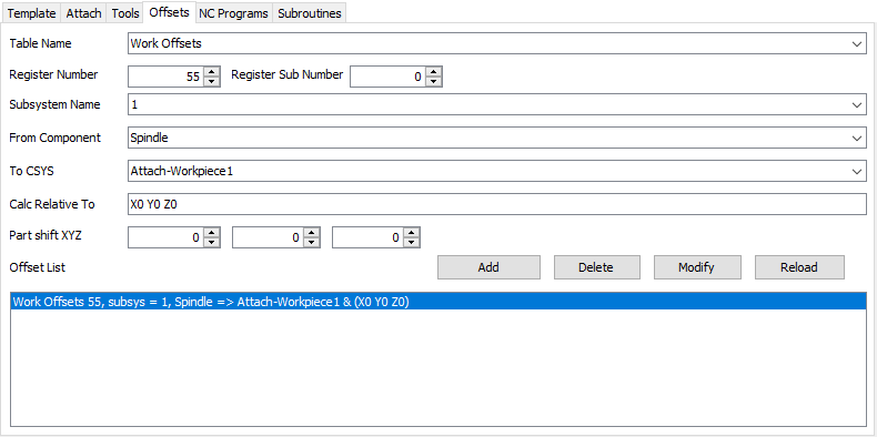
Table Name:
Use to select the G-Code Table that you want to define. The Table Name pull-down list contains the following Vericut G-Code tables: None, Program Zero, Work Offsets, and Base Work Offset. Choose the Table Name from the pull-down list.
- Program Zero: The Program Zero table is used to specify the programmed zero location of a G-Code NC program file taking Tool Length Compensation into consideration.
- Work Offsets: The Work Offsets table is used to store the work coordinate system offset (fixture offset) values.
- Base Work Offset: The Base Work Offset table is used to specify the location from which work offsets are based.
- Register Number: Use to specify the register number that will be used by Vericut to access the corresponding table data. The register number may correspond to an offset register number, or an integer value, as required by a particular table. Enter the register number in the Register Number text field.
Subsystem Name:
Use to specify name of the machine subsystem for which the table is being defined. Select the subsystem name from the pull-down list.
From Component:
Enter the name of the component that represents the "from" point for determining the program zero offset or choose a component from the drop-down list. Vericut will use the origin of the specified component. The default "From Component" is "tool".
To CSYS:
Select the coordinate system name that represents the "to" point for determining the offset from the To coordinate system pull-down list. The coordinates of the coordinate system origin are used as the "to" point.
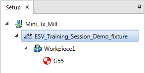
Note a coordinate system is created for each workpiece into the TNG document.
Calc Relative to:
This feature enables you to have a relational offset recalculated in the machine position where the offset will be used. The new position is immediately calculated and stored and
therefore is not dependent on the machine position when the offset is activated.
Part Shift XYZ:
This feature enables you to define an additional shift to the Offset being passed. This will populate the "Translate To Location" field in Vericut.
Offset List:
Displays the list of G-Code Table records currently defined.
- Add: Adds a G-Code Table record to the Offset List based on the current Table Name, Register Number, Subsystem Name, From Component and To CSYS settings.
- Delete: Deletes the G-Code Table record highlighted in the Offset List.
- Modify: Modifies the G-Code Table record highlighted in the Offset List with the current Table Name, Register Number, Subsystem Name, From Component and To CSYS settings.
- Reload: this button allows clearing the list then reloading all work offsets from the current document. This can be useful if the user has values saved in the settings file that he no longer wants to use.
NC Programs
The features on the NC Programs tab enable you to generate NC Programs from the ESPRIT part file, or specify existing NC programs, to be passed to Vericut. You must either: choose to generate an NC program or you must provide at least one existing NC program file.
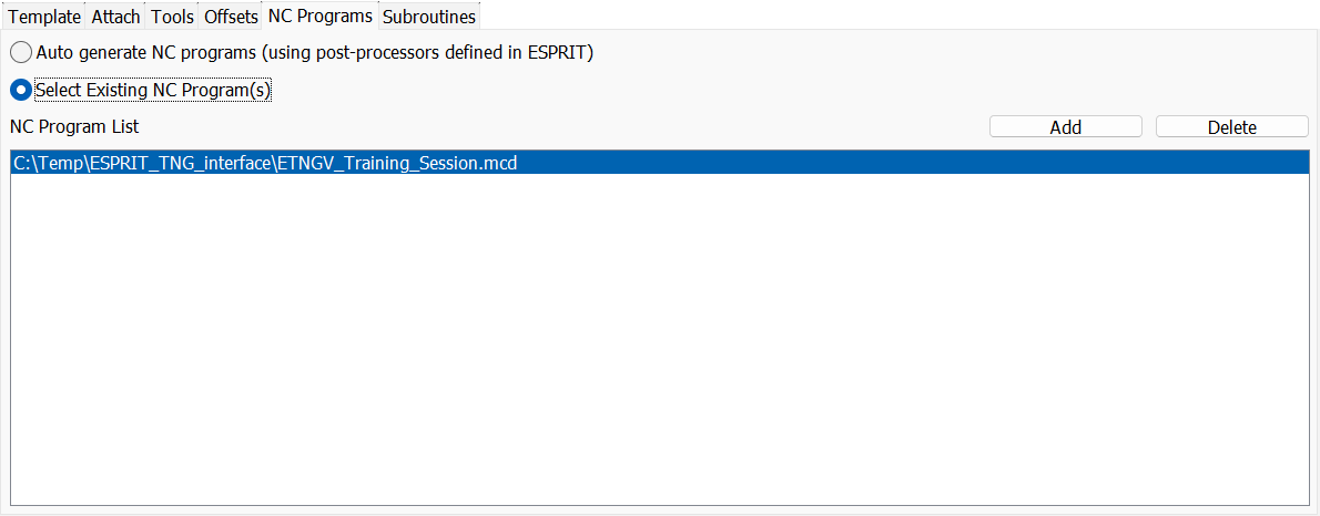
Auto generate NC programs (using post-processors defined in ESPRIT):
This check button is provided if the user wants to auto-generate NC programs using post-processors defined in ESPRIT.
Select Existing NC Program(s):
Use this feature to activate \"NC Program List\" and the Add and Delete buttons.
NC Program List:
The NC Program List displays the NC programs that will be passed to Vericut.
- Add: Use the Add button to display a file selection window and use it to select the required NC program files.
- Delete: Use to delete the highlighted NC program file(s) from the NC Program List.
Subroutines
The features on the Subroutines tab enable you to specify existing NC Subroutines, to be passed to Vericut.
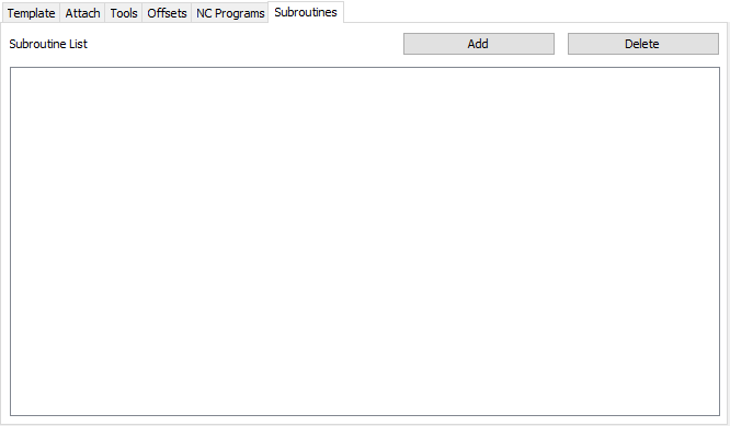
Subroutine List:
The Subroutine List displays the NC Subroutines that will be passed to Vericut.
- Add: Use the Add button to display a file selection window and use it to select the required NC Subroutines files.
- Delete: Use to delete the highlighted NC Subroutines file(s) from the Subroutine List.
Settings
The Settings dialog can be launched by clicking on the ![]() Settings button.
Settings button.
This mechanism can be used to specify global options for interface display & behavior. These user options are global and are applicable to all sessions of the interface including the current session.
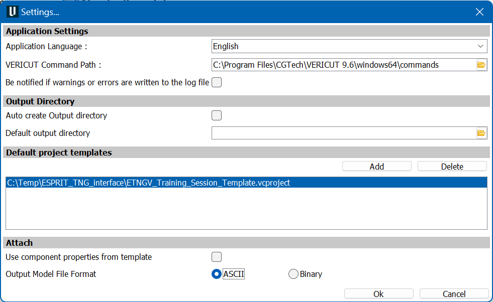
The dialog is divided into four sections; Application Settings, 'Output Directory', 'Default project templates' and 'Attach'.
Application Settings
Application Language:
User can change the language of the interface here, runtime, by selecting any of the language on the drop-down menu provided. If, for the language specified, local file will not be found to exist, error message will be displayed in red font.
Vericut Command Path:
User can edit/specify here the path for 'commands' folder which contains the Vericut batch file, inside Vericut installation directory. Use the ![]() button to display a file selection window and use it to select the 'commands' folder.
button to display a file selection window and use it to select the 'commands' folder.
Be notified if warnings or errors are written to the log file:
by checking this checkbox, the user enables a mechanism that show a warning when an error or a warning occurs during the export.
The button 'See log file' allows opening the log file (or Activity file) in an editor, and seeing entries added.
Note: this area disappears by refreshing the interface or opening another ESPRIT file.
Output Directory
Auto Create Output Directory:
User can choose to have interface auto create output directory so that user does not have to provide one explicitly. This is possible by checking Auto Create Output Directory check-box. In this case, every time user opens interface, a directory named output will be created (if does not already exist) underneath the main directory in which corresponding Esprit project is located. This newly created output directory will be chosen as an interface output directory and will be displayed to the user.
Default Output Directory:
Un-checking Auto Create Output Directory checkbox enables Default Output Directory text box and ![]() button which otherwise are disabled. If user wants to output all interface exported files to one default folder, it is possible by providing path at Default Output Directory text box. User can also locate path using
button which otherwise are disabled. If user wants to output all interface exported files to one default folder, it is possible by providing path at Default Output Directory text box. User can also locate path using ![]() button. User defined path here will be chosen as interface output directory and displayed on the interface in all future interface sessions.
button. User defined path here will be chosen as interface output directory and displayed on the interface in all future interface sessions.
Default Project Templates:
List of Vericut project file that can be used as project templates can be specified here.
Files listed here will be displayed in Project Directory pull-down list on the main interface window.
- Add: Use the Add button to display a file selection window and use it to select the required Project Template.
- Delete: Use to delete the highlighted Project Template from the List.
Attach
Use component properties from template:
if checked the output Stock, Fixture and Design component names will be taken from the Vericut Template
Output Model File Format:
User can define here output STL file format i.e., ASCII or Binary
Generate buttons

Refresh
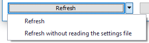
The Refresh button, rescans for necessary data in the Esprit TNG system, and the Settings file, and then loads the data back to the Esprit-to-Vericut interface. If changes have been made to the Esprit TNG project, Refresh needs to be used so that all of the Esprit TNG project changes are updated in the Esprit TNG-to-Vericut interface data fields.
Refresh without reading the settings file:
Re-scans for necessary data in the Esprit TNG system, without the settings file.
Caution must be exercised when using the Refresh feature. If changes have been made to the settings in the Esprit TNG-to-Vericut interface and saved as described in the Settings File section above, using the Refresh feature would result in all of the current changes being lost and the Esprit TNG-to-Vericut interface data fields will revert back to their previous settings.
Output Files:
Outputs all files, for all operations, including the selected models, tool library files, updated project and setup files, and the \"operations\" file that assembles all of this information into a Vericut \"project\" file. It also updates the Settings File for the current ESPRIT TNG part file.
Run Vericut:
Same as Output Files but also launches Vericut.
Preferences
Preferences File
Also known as prefs file, stores all user specified global settings for interface operation. The settings stored are called global because they are responsible for overall look & feel and operational behavior of the interface. They are not tied to any specific Esprit TNG project. By default, Preferences file is generated at local Application Data directory inside %APPDATA%/CGTech/Esprit/ directory.
Ref: C:\Users\username\AppData\Roaming\CGTech\Esprit\tngv_user.prefs
Project Settings File
All of the fields into which a user requires to enter text are saved in an Esprit TNG project specific settings file. The settings file is saved internally with the project. When the interface is opened, it first checks that whether the corresponding project has settings file saved along with it, and if so, loads the last saved settings from that.
If no settings file is found for the project, all fields in the interface will remain blank. In order to, save the settings file with the Esprit project, so that settings will be restored when opening the file later, the Esprit file must be saved. With that, settings file will automatically be updated with the current data of the interface, when user clicks on either of the Output Files or Run Vericut button.
Activity File
The Esprit TNG-to-Vericut interface tries its best to ensure a valid operation sequence, but when something does go wrong, an entry is added to the Activity File. Any attempt to execute an unsupported operation is also recorded here. At last, any undesirable behavior of the Esprit-to-Vericut Interface software is also recorded here. In the event of reporting a problem to CGTech technical support, it would be desirable to have Activity file along with any example file. This will greatly expedite the process of resolving the problem.
By default, activity file is generated at local Application Data directory inside %APPDATA%/CGTech/Esprit/ directory. Example path would be same as that of prefs file. However, by using environment variable CGTECH_TNGV_ACTIVITY user can provide custom path for activity file generation.
Ref: C:\Users\username\AppData\Roaming\CGTech\Esprit\vericut_addin_tng_activity.txt