Surface to Solid Converter
Location:
Utilities tab >  (Surface to Solid)
Introduction to the Surface to Solid Converter
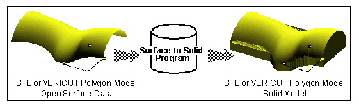
The Surface to Solid Converter creates solid models from open surface STL and Vericut Polygon Model files. Parent surface(s) can be offset, and then projected to a plane to create a solid model. This converter is particularly useful to create casting/forging stock models from design surface data. The Surface to Solid Converter has the ability to output data as Vericut or STL model files, in ASCII or binary file format. Solid model files can be created from surfaces interactively in Vericut, via batch processing, or outside of Vericut by running the "sur2stk" command file file located in the "commands" directory of your Vericut installation.
Surface to Solid Converter window
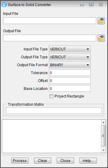
Input File — The name of the file containing the surface data to create a solid from. Enter the /path/filename in the Input File text field or click on the  (Browse) icon to display the Select Input File file selection window and use it to specify the /path/filename.
Output File — The name of the file to receive converted geometry. Enter the /path/filename in the Output File text field or click on the (Browse) icon to display the Select Output File file selection window and use it to specify the /path/filename.
Input File Type — The type of input file to read. Options are: Vericut or STL.
Output File Type — Same as Input File Type, except applicable to the output file.
Output File Format — The format of the output file. Options are: BINARY or ASCII.
Tolerance — Use to specify the tolerance used when offsetting and projecting the surface(s) to create a solid model.
Offset — Distance and direction in which to offset the design surface, as applied in the Z direction. For example: ".100" applies an offset of .100 to the surface in the Z+ direction. A value like "-.100", applies the offset in the Z- direction, effectively "shrinking" the model.
Base Location — Specifies the Z value of the plane to become the base of the solid model. The surface is projected along the Z-axis to this plane.
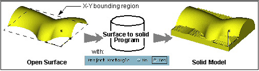
Project Rectangle — When active, expands surface edges to create a rectangular base. The size of the rectangular base is determined by the X-Y bounding region of the surface data.
Transformation Matrix — Transforms the solid model. Use this feature is used when Offset and Base Location values were entered with respect to a tool path coordinate system instead of the model coordinate system. Matrix values correspond to MSYS record values that appear in a NX CLS file: dx,dy,dz,Ivx,Jvx,Kvx,Ivy,Jvy,Kvy where "dx,dy,dz" specify the distance to the local coordinate system origin, and "Ivx,Jvx,Kvx, Ivy,Jvy,Kvy" specify the orientation of the local coordinate system X and Y axis vectors with respect to the surface model coordinate system.
Process — Process (convert) the surface data according to the current window settings. Converted geometry is written to the Output File. Error and informational messages from the process are sent to the Surface to Solid Converter window message area.
Clear — Clears the Surface to Solid Converter window message area.
Close — Closes the Surface to Solid Converter window.
Help — Displays this Help page. (You can also use the F1 key to display this Help page).