Surfcam-to-Vericut Interface (SCV)
Overview
SCV is a licensed software program that provides a Surfcam to Vericut data transfer connection.
Software Requirements: Surfcam Interface
Licensing Requirements
CGTech Licensing:
Surfcam Interface
Installation & Configuration: Surfcam Interface
The following section describes how to install the Surfcam-to-Vericut Interface. SCV is distributed as three files located in the below directory of the Vericut installation.
C:\Program Files\cgtech\Vericut x.x.x\windows64\surfcam
- Vericut_Interface.dll (the code)
- StyleSheet.xsl (supporting code)
- SurfcamRes.local (language translation)
Steps to configure SCV:
1. Copy the Surfacam folder from the Vericut installation to the Surfcam installation
-
Copy from:
C:\Program Files\cgtech\Vericut x.x.x\windows64\surfcam -
Copy to:
C:\Users\Public\Surfcam\Surfcam_xx\UserApps\VERICUT -
Note: You will have to create UserApps and VERICUT directories manually.
2. Edit the 'SURFCAM.INI' file in order for Surfcam to get the location of addin dll.
-
Note: The SURFCAM.INI file can be found at:
"C:\Users\Public\Surfcam\Surfcamx.x\Config" location. -
Note:You will have to search for 'Specify Plug-Ins option' section. And make the following edits:
;\_\_\_\_\_\_\_\_\_\_\_ Specify Plug-Ins option
\_\_\_\_\_\_\_\_\_\_\_\_
UserApplications=1
UserApp1=C:\Users\Public\Surfcam\Surfcam*x.x*\UserApps\VERICUT\Vericut_Interface.dll,\"VERICUTInterface\"
- Save the file.
Environment variables: Surfcam Interface
To enable the Surfcam Interface to locate the necessary Vericut files, the following environment variables must be defined:
Environment Variables: Description & Example
CGTECH_INSTALL
Purpose: Defines the Vericut installation folder.
Example: For Vericut 9.7, set to: C:\Program Files\CGTech\Vericut 9.7
CGTECH_PRODUCTS
Purpose: Specifies the folder for the operating system running Vericut (windows64).
Example: For Vericut 9.7, set to:
C:\Program Files\CGTech\Vericut 9.7\windows64
LSHOST
Purpose: Defines the name of the license server computer.
Example: localhost
CGTECH_SINGLE_PLATFORM (Optional)
Purpose: Specifies if Vericut is running on a single platform.
Example: CGTECH_SINGLE_PLATFORM=YES
CGTECH_SURFCAM_LANGUAGE (Optional)
Purpose: If you want the interface to use something other than US English, the variable can specify path of the local file.
Available Languages: French, Chinese, Italian, Portuguese, and Japanese.
Example:
CGTECH_SURFCAM_LANGUAGE=
C:\Program Files\CGTech\VERICUT 9.7\windows64\surfcam\french
CGTECH_SURFCAM_LOCALE (Optional)
Purpose: Is used to define name of the language; which user prefers to display on the interface.
Example: CGTECH_SURFCAM_LOCALE=french
Microsoft Redistributables: Surfcam Interface
The Surfcam-to-Vericut Interface (SCV) may require the installation of Microsoft Redistributables, specifically the Windows C++ run-time libraries. These libraries ensure compatibility and proper functioning of the interface, allowing seamless data transfer between Surfcam and Vericut for manufacturing simulation.
Note: A runtime library is a collection of low-level compiler support routines and functions that are used by virtually all programs compiled with GCC (GNU Compiler Collection) and can be downloaded here.
Documentation: Surfcam Interface
Overview:
The Surfcam interface exports manufacturing data from Surfcam to Vericut, ensuring a seamless transition for simulation. It automatically configures the necessary Vericut setup requirements and launches the simulation, ready to play.
Vericut Simulation Setup Requirements:
To run a successful simulation in Vericut, the following steps must be completed:
1. Select a VMC (Vericut Machine Configuration) – Define the machine setup for simulation.
2. Select and Orient Stock, Fixture, and Design Models – Ensure correct positioning of components.
3. Select NC Programs & Subroutines – Load the necessary machining programs.
4. Define Cutting Tools – Specify the tools used in the machining process.
5. Define Work Offsets Tables – Configure coordinate systems for accurate machining.
Accessing the Surfcam-to-Vericut Interface
From the SURFCAM Menus, select Add Ins > VERICUT Interface
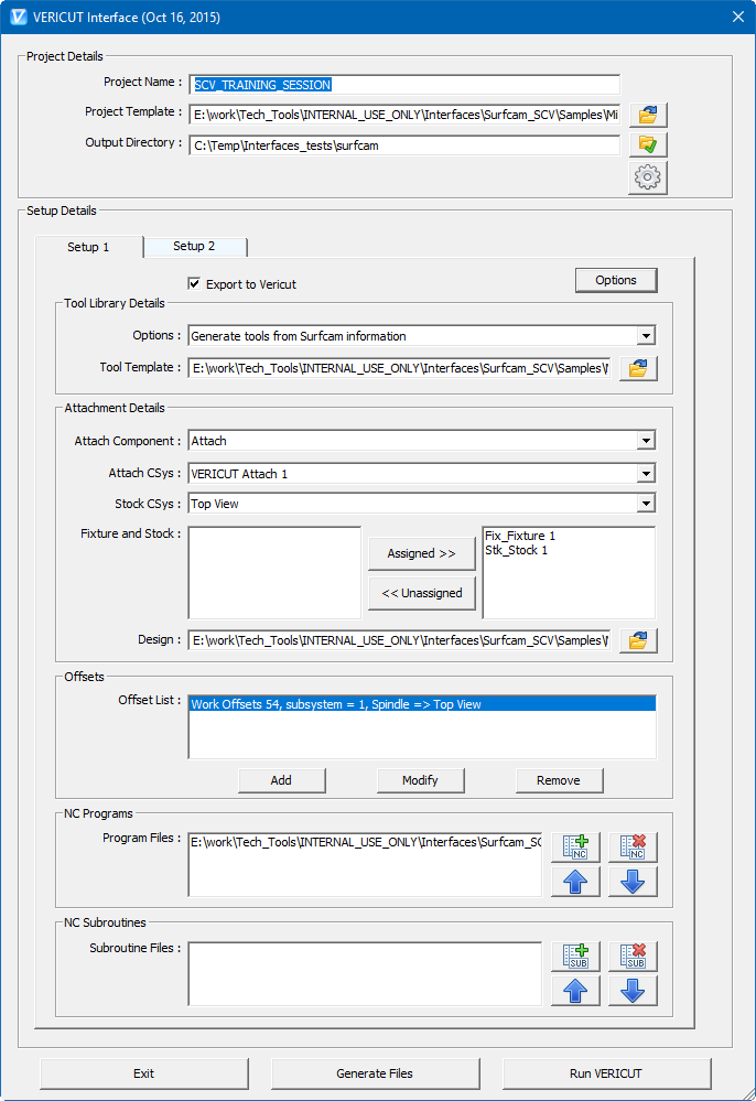
When you trigger ESV, you should see a window similar to this:
Important Note:
The Surfcam interface requires an active NC Manufacturing file to function properly with Vericut.
License Handling
- The interface checks out a license when opened.
- The interface checks in the license when closed.
As visible, in the above image, interface dialog is divided into two parts: 'Project Details' and 'Setup Details'. 'Project details' group contains fields to provide general project information such as project name, project template, output directory path and project specific settings. 'Setup details' group contains fields for setup specific information. Each setup is displayed into individual tab dialog and with distinct color.
At the bottom of the dialog, buttons are provided for user to generate Vericut files from Surfcam project manufacturing data or to generate files along with launching Vericut or simply exit the interface.
All the corresponding information fields are arranged together into corresponding group box.
Project Details
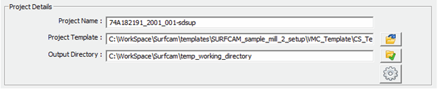
Project Name – ‘Base’ name for the output Vericut files is entered here. By default, name of the Surfcam project file is used.
Project Template – “path/filename” of an existing project template file can be specified here. Alternatively, browse button can be used, as well, to open file  browse & selection window to locate the template file.
Output Directory – “\path\” of the directory where user wants to output all Vericut files can be specified here or user can also use the browse button  to open a directory browse & selection window to locate the directory path.
Settings – ‘Settings’ button  is provided to display the application settings window, which enables user to change the language used in the interface and commands folder of Vericut installation.
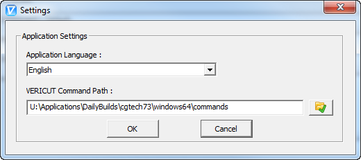
Settings dialog is used to store controls which enables user to edit key settings of the interface.
Application Language – List of supported languages, for the interface, are stored into pull-down list, here. User can select any of the desired language from the pull-down list, which would become the display language for the interface, after pressing the ‘OK’ button. If the localization file for the selected language is not found, an error message, in red font appears on the dialog alongside of the “Application Language” title.
Vericut Command Path – User can view/edit the \path for the command folder of Vericut installation.
Setup Details

Export to Vericut – In-case of multi-setups, if user does not prefer to output particular setup data, it can be done by de-selecting this check box. By default, ‘Export to Vericut’ checkbox is checked.
Options – ‘Options’ button is provided to open up dialog, in which user can set ‘Setup specific settings’.
Setup Specific Options
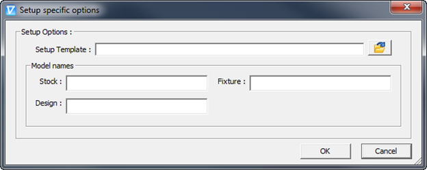
Setup Template – “path/filename” of an existing setup template file can be specified here. Alternatively, browse button  can be used, as well, to open file browse & selection window to locate the template file. In the case if setup template file is not selected by the user, project template file would be considered. In the event of both project and setup template files are specified, setup template file gets a priority.
Model Names – Text fields are given to specify model names for stock, fixture and design, separately. If no names are specified, default names would be used.
Tool Library Details
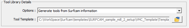
Options – User has to make a choice for any one of the provided options to export tooling information to the Vericut.
Generate tools from Surfcam information – With this option selected, Surfcam-to-Vericut interface generates tool library file from the information coming out from Surfcam and provided tool template file.
Use tools from project/setup template – User can choose to use the tools from the tool library file, mentioned into project or setup template file.
Use existing tool library – Alternatively, user can also locate existing tool file, by using file browse & selection window.
Tool Template – Similar to project template file or setup template file, tool template file can be specified by entering full-path manually or by locating file, using file browse & selection window, which can be opened using browse button .
Tool Template File Tool template file contains all the Vericut holder definition and their corresponding gage point information for the tools being used into Surfcam project.
Tool template file can be specified into project or setup template file. It can also be defined by locating it using file browse & selection window.
Tool template file is formatted same as Vericut tool library file. Interface parses tool template file and take the holder and gage point information from the tool with the same ID as that of Surfcam tool ID into Vericut. Tool ID for Surfcam tool into Vericut is created by appending Surfcam tool description with the string “–TN_” following by tool number.
Moreover, default tool can also be defined into tool template file. Id of the default tool should be “Default Tool”. An individual default tool can be defined for each type of operation, i.e. default tool for milling tools and default tool for turning tools etc.
Attachment Details
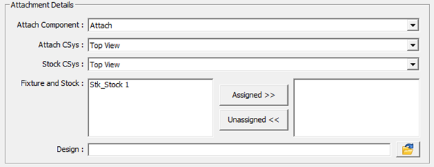
Attach Component – Attach component’s list is populated by parsing machine file, defined in project/setup template file. Selected component acts as “Attach Component” for the stock into Vericut.
Attach CSys – The list displays, names of all the coordinate systems defined into Surfcam project file. Selected coordinate system would be used to locate stock and fixture models on to machine in Vericut.
Stock CSys – Stock coordinate system is used to reorient stock model into next setup from the current one. “Stock CSys” list contains name of all the coordinate systems defined into Surfcam project file.
Fixture and Stock – The ‘Unassigned Models’ list contains all stock and fixture models from the Surfcam project configured for the specific Setup. All model names will be prefixed by their type: "Stk" for stocks and "Fix" for fixtures.
“Assigned >>” - Button is used to move selected models in the ‘Unassigned Models’ list to the ‘Assigned Models’ list.
“Unassigned <<” - button is used to move selected (highlighted) models in the ‘Assigned Models’ list to the ‘Unassigned Models’ list. Models into ‘Assigned Models’ list will be exported to Vericut.
Design – Surfcam ‘Part’ file (‘Design’ file in Vericut terminology), needs to be saved from Surfcam as STL file, beforehand, from Surfcam itself to be able to use it as ‘Design’ file into Vericut. User can locate newly created file here, using file browse & selection window, using the browse button .
Offsets
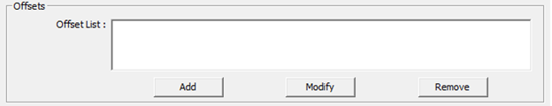
Offset List – Displays the list of currently defined offsets.
Add – Opens up ‘Offsets’ dialog (as shown in the picture below) giving user an ability to define new offset.
Modify – Modifies currently selected offset from the list. It also opens up the ‘Offsets’ dialog with corresponding offset selected and ready to be modified.
Delete – Deletes the selected offset record from the ‘Offsets’ list.
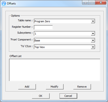
Table Name – The Table name pull-down list contains the following Vericut G-Code tables: ‘Program Zero’, ‘Work Offsets’, and ‘Base Work Offset’. Selected table name is used to identify the type of the offset table to be added or modified.
Register Number – Register number value has to be integer value. In case of invalid entry by the user, an error message in red font appears alongside of the text field. The register number is used by Vericut to access corresponding table data.
Subsystems – Subsystem names are populated from the Vericut machine file, defined into Project/Setup template file.
‘From’ Component – ‘From’ component list is made of all machine components defined into machine file. Selected component is used for determining origin point of the offset.
‘To’ CSys – ‘To’ Csys list is made of all coordinate system defined into Surfcam project file. Selected component is used for determining destination point of the offset.
NC Programs
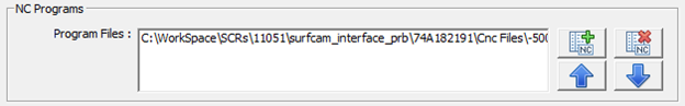
Program files: – 'Program files' list displays the NC programs those are going to be passed to VERICUT. Add  and Delete
  buttons are provided to add and remove NC programs to the list. User can also reorder programs into the list by using Up
  and Down
  buttons.
Subroutines
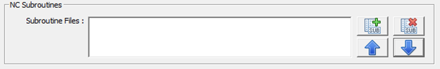
Subroutine files: – 'Subroutine files' list displays the subroutines specified by the user those are going to be passed to VERICUT. Similar to NC programs, Add and Delete buttons are provided to add and remove subroutines to the list. User can also reorder subroutines into the list by using Up and Down buttons.
Button Panel

Exit – ‘Exit’ button is provided to exit the interface. But before invoking exiting event, interface updates preference file with latest user changes.
Generate Files – If user chooses to output Vericut files without launching Vericut, it can be achieved with the use of ‘Generate Files’ button.
Run Vericut – ‘Run Vericut’ button is provided to output all Vericut files and launch Vericut with newly created files. User’s project specific settings are saved into settings file right before outputting files.
Preferences
Preferences File
All the global settings for the interface are saved as preference file. The file is created and saved at current user directory with the name ‘Vericut_Surfcam_user.prefs’. Preference file contains data such as interface dialog location, size; various file filters for browse dialogs and other project data which can be common amongst various Surfcam projects. Preference file is updated and saved at the time when user exits interface by pressing on “Exit” button.
Purpose of maintaining preference file is to eliminate need of entering various data manually each time opening a new Surfcam project and also maintaining user defined window size and location, each time dialog is opened.
Ref: C:\Users\username\Vericut_Surfcam_user.prefs
Settings File
Unlike preference file, which stores global settings for the interface which remains unchanged amongst various Surfcam projects, settings file stores Surfcam project specific settings. Settings file is stored with the same name as corresponding Surfcam project file and at the same location as that of the Surfcam project file, with the file extension of ‘*.vcsc_data’.
When Surfcam-to-Vericut Interface opens up, it first checks to see if the project currently has settings file saved along with it, and if so, loads the previously saved field settings. If no settings file is found for the project, all project specific fields in the interface remains blank. Settings file is updated and saved when ‘Output Files’ or ‘Run Vericut’ is selected, by the user.
Activity File
The Surfcam-to-Vericut interface will do its best to ensure a valid operation sequence, but when something does go wrong, an entry is added to the Activity File. Any attempt to execute an unsupported operation will also be recorded here. Finally, any undesirable behavior of the Surfcam-to-Vericut Interface software is also recorded here. The Activity File is located at the interface installation directory.
In the event of reporting a problem to CGTech technical support, it would be desirable to have ‘Activity file’ along with any example file. This will greatly expedite the process of resolving the problem.
Ref: C:\Users\username\AppData\Roaming\CGTech\Surfcam\vericut_surfcam_activity.log