VDA Converter
Introduction to the VDA Converter
The VDA Converter converts (translates) geometry conforming to the VDA (Verband der Automobilindustrie Surface Interface) 2.0 specification to Stereolithography or Vericut Polygon model files. This converter lets you make the most of your existing CAD data by enabling you to import complex castings, clamps, fixtures, and other design models into Vericut, as well as generate design point data for use by the AUTO-DIFF function in Vericut. VDA data can be converted interactively in Vericut, via batch processing, or outside of Vericut by running the "vda" command file.
VDA data and version support
Vericut's VDAFS Converter can convert the VDA data elements listed below. The elements that are actually converted depend on the type of output file being generated by the converter.
- POINT
- PSET (point set)
- MDI (set of point/vectors)
- SURF (base surface)
- FACE (trimmed surface)
VDA Converter window
Location:
CGTech > Vericut > windows64 > commands > vda.bat
Note: The VDA Converter is no longer included in the Vericut GUI but this feature can still accessed by opening a finder window, navigating to your installed Vericut product and locating the vda.bat file following the pathway listed above.
The VDA Converter converts (translates) VDA geometry to Stereolithography or Vericut Polygon model files. This converter is used to import complex castings, clamps, fixtures, and other design models into Vericut, as well as generate design point data for use by the AUTO-DIFF function in Vericut. VDA data can be converted interactively in Vericut, via batch processing, or as a stand-alone utility outside of Vericut by running the "vda" command file located in the "commands" directory of your Vericut installation.
Tip: When expecting to use VDA data for solid models in Vericut, ensure that surface normal vectors all point outwards in the CAD model prior to outputting the VDA data.
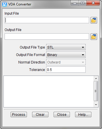
Input File — The name of the file containing the VDA data to convert. Enter the /path/filename in the Input File text field or click on the  (Browse) icon to display the Select Input File file selection window and use it to specify the /path/filename.
Output File — The name of the file to receive converted geometry. Enter the /path/filename in the Output File text field or click on the (Browse) icon to display the Select Output File file selection window and use it to specify the /path/filename.
Output File Type — The type of output file to create. Options are: Vericut, STL or POINT (Design Points file). The VDA data elements that are converted depend on the type of file being generated.
Output File Format — The format of the output file. Options are: BINARY or ASCII. Option not applicable to Point output file types.
Normal Direction — The direction in which surface normal vectors point, as viewed in the CAD system. Feature only applicable to Vericut output file types. Options: OUTWARD or INWARD.
Tolerance — Use to specify the amount of chordal deviation allowed in 3-D space from the VDA surface when creating the converted surface. The converted surface is approximated using "facets", or triangles. This option not applicable to Output File Type: POINT.
Process — Processes (converts) the VDA data according to the current window settings. Converted geometry is written to the Output File. Error and informational messages from the process are sent to the VDA Converter window message area, and to a log file named "vda.log" created in the working directory.
Clear — Clears the VDA Converter window message area.
Close — Closes the VDA Converter window.
Help — Displays this Help page. (You can also use the F1 key to display this Help page.)