Notes about Drill Cycle Logic
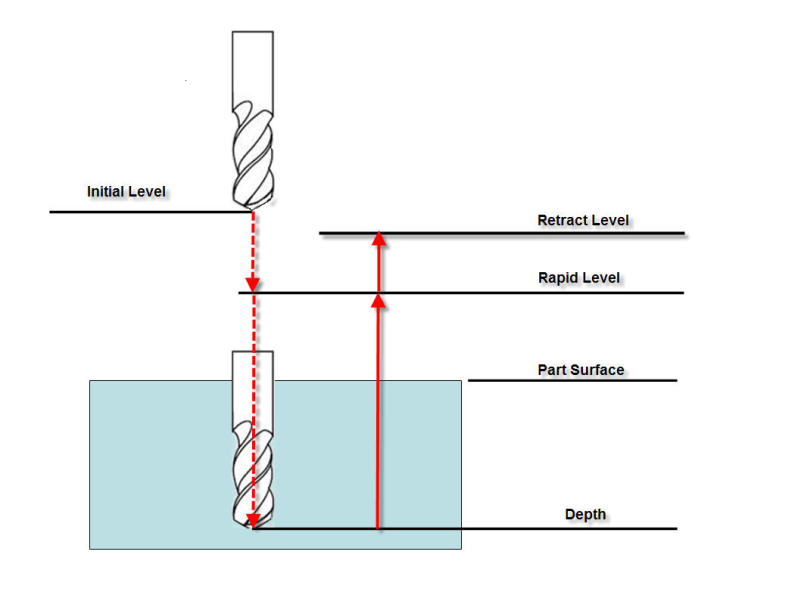
Drill cycles define 4 values (directly or indirectly): the Rapid Level, the Part Surface, the Depth, and the Retract Level. Each of these values are specified directly (with an absolute location), or as an incremental distance from some other known location. See the diagram below. The concept with the new logic is to specify these 4 levels directly in the control using 4 simple macros. All other macros and switches are ignored.
DETAILS:
Only the settings from the following macros are used:
The text field for each of these macros indicates the meaning of the value passed. The options are:
0 – Absolute
1 – Incremental distance from the Initial Level
2 – Incremental distance from the Rapid Level
3 – Incremental distance from the Part Surface
4 – Incremental distance from the Depth
5 – Incremental distance from the Retract Level
6 – Value specified with Local Axis Position (all 3 axis must be specified)
All values (text and numeric) set with these macros are modal.
See the Vericut Macros section, in the Vericut Help Library for information on these, and all Vericut macros.
NOTES:
- You cannot set the override to a value that references itself as the incremental origin. For example, if you are setting the Part Surface, you can not pass it an override text value of "3" (Incremental distance from the Part Surface).
- ZAxisMotion
On a Fanuc control, a G81 block defines the cycle parameters and then the corresponding drill cycle is executed on each motion until the cycle is cancelled. A drill cycle is also executed on the G81 block even if there is no motion on this block.
The depth is defined by SetCycleDepth macro. If the drill cycle is to be executed on a block where there is not motion, then the SetMotionFlag macro must be called.
EXAMPLES:
Fanuc:
Using fan_subs.VcProject from the /samples/ directory of your Vericut installation.
In the fan_subs example, the drilling is done in a subroutine with arguments passed which define the cycle. For example:
G#3G99Z-#26R.1F#9Q.1
Here, #3 is 81, G99 specifies the retract level, Z specifies the depth, and R specifies the Rapid Level.
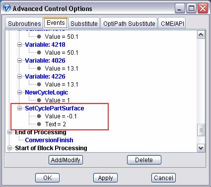
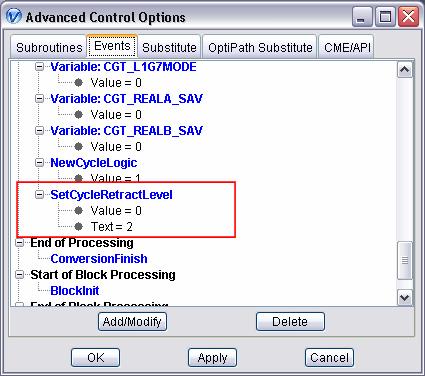
Fanuc does not specify Part Surface. This is a level that we need to have specified. The solution is to define it to be .1 below the Rapid Level. This can be done in the Start of Processing event as shown below.
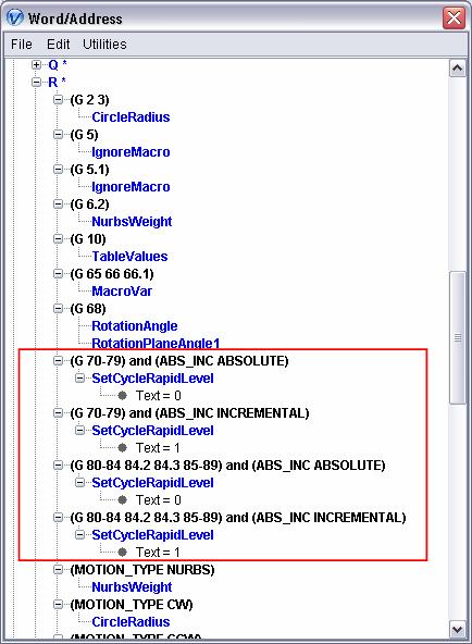
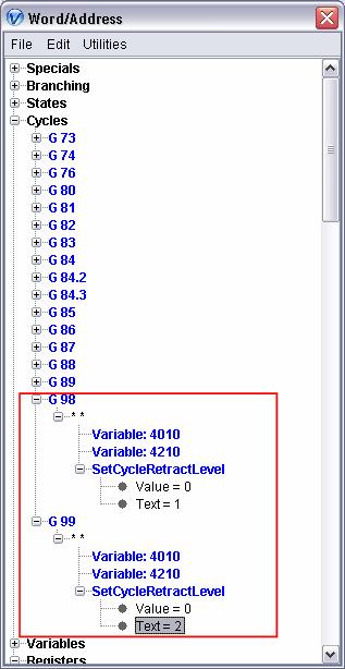
Next, the Rapid Level is dependent on if you are incremental mode or absolute mode. This must now be set using conditionals in the Word/Address table. For example:
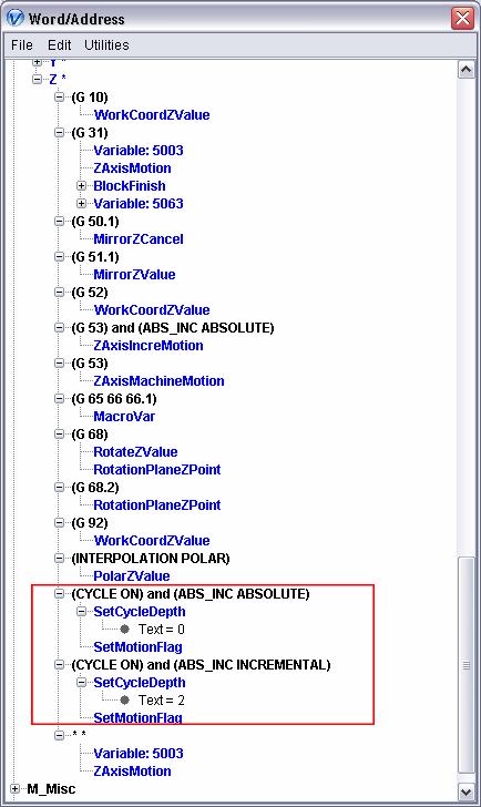
Next the Depth level is also dependent on the Absolute/Incremental mode. The Depth level might also be dependent on the Motion Plane. The Motion Plane dependency is not configured in this example. In this example, we will assume that whenever the Depth is set, a drill cycle should be executed (SetMotionFlag will be called).
The Retract Level is either the Initial Level or the Rapid Level. We will define this as an incremental distance of zero from the corresponding level.
Heidenhain Mill Plus:
Using dmg_dmu60t_heimplus.VcProject from the /showroom/ directory of your Vericut installation
A common drill cycle would look something like:
G81 X.1 Y.1 Z-1 F10 S500 M3
G79 X0 Y0 Z0
G81 specifies the drill cycle, and this drill cycle is to be executed on command. G79 is the command, and the Z on this block specifies the Parts Surface.
The Heidenhain control does not have a Retract Level. We will define this to be an incremental distance of zero from the Rapid Level. This can be set during the Start of Processing event.
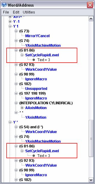
Next the Rapid Level is defined with Y on a G81 block. It is defined to be incremental from Part Surface. Since we have a Y -1, a Y 1, and a Y *, this setting must be made to each of these as shown below:
Next, the Depth is specified with the Z on the G81 block as shown below:
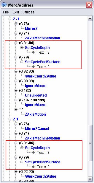
The Part Surface is defined with a Z on a G79 block (as shown above).
NOTE: This might be motion plane dependent. This is not configured into this control.