Graphics Area
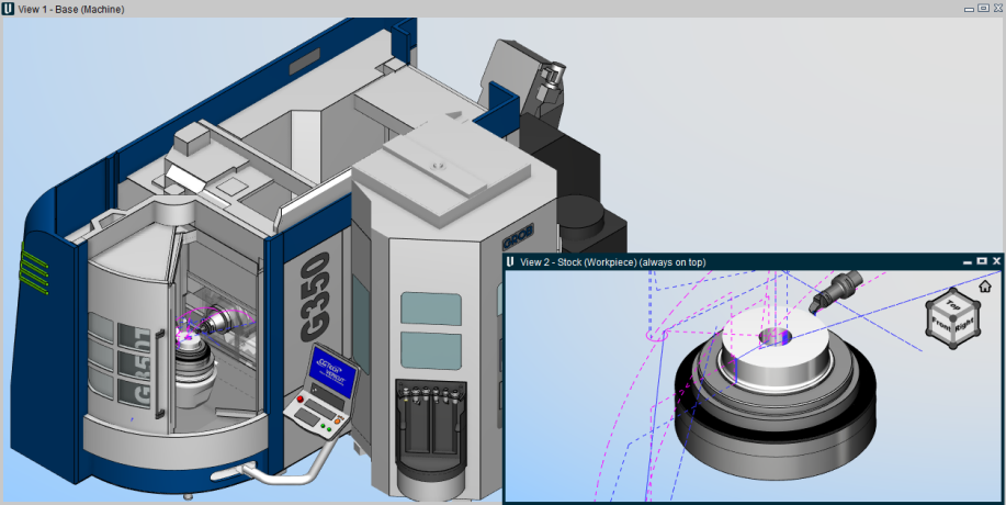
The graphics area displays the active views contained the Vericut Review File (.vcreview).
The Graphics Area display and the Graphics Area right mouse button menus will vary depending on whether the review file was create in Vericut Simulation, Vericut Composite Simulation, or in Vericut Drill and Fastener Simulation.
Vericut Simulation Review Files
The Toolpath Display
As the NC program is replayed, a line representing the motion of the tool control point is displayed in the graphics area.
Motions that remove material are displayed as solid lines with a default color of the foreground color. Motions that do not remove material are displayed as dashed lines with a default color of magenta. The line representing the motion of the current NC program record is highlighted with a default color of red. The tool image is displayed at the location of the current NC program record.
The color of the lines can be changed using the Cut Line, Non-Cut Line, and Circular Motion options found in the menu that is displayed when using the right mouse button in the graphics area or the NC Program listing area.
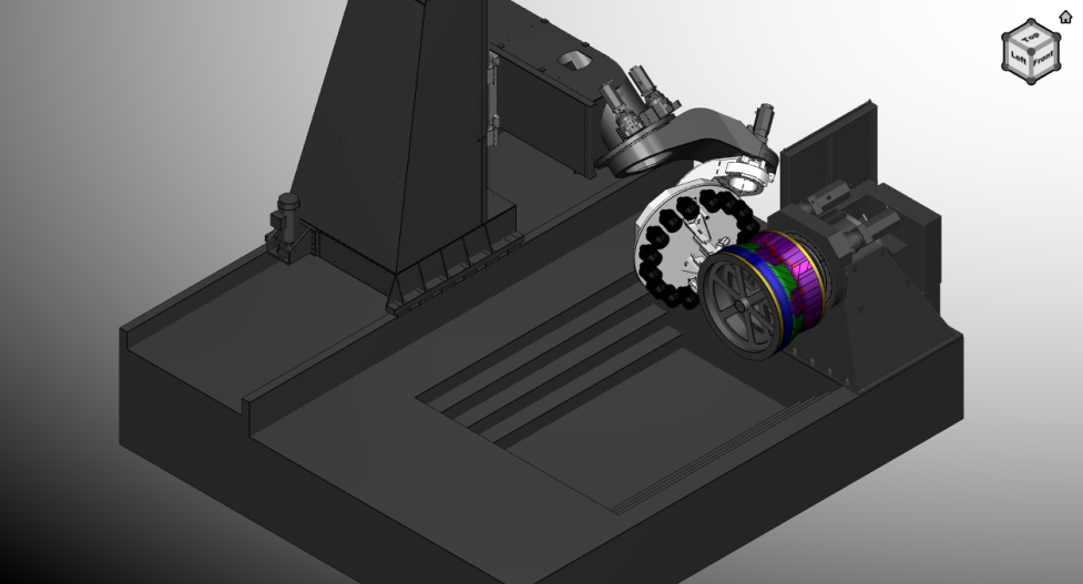
Vericut Drill and Fastener Simulation Review Files
The Drill/Fastener Path Display
As the NC program is replayed, the machine will move to each previously simulated hole/fastener location and move through the programmed drill/fastener cycle at each location.
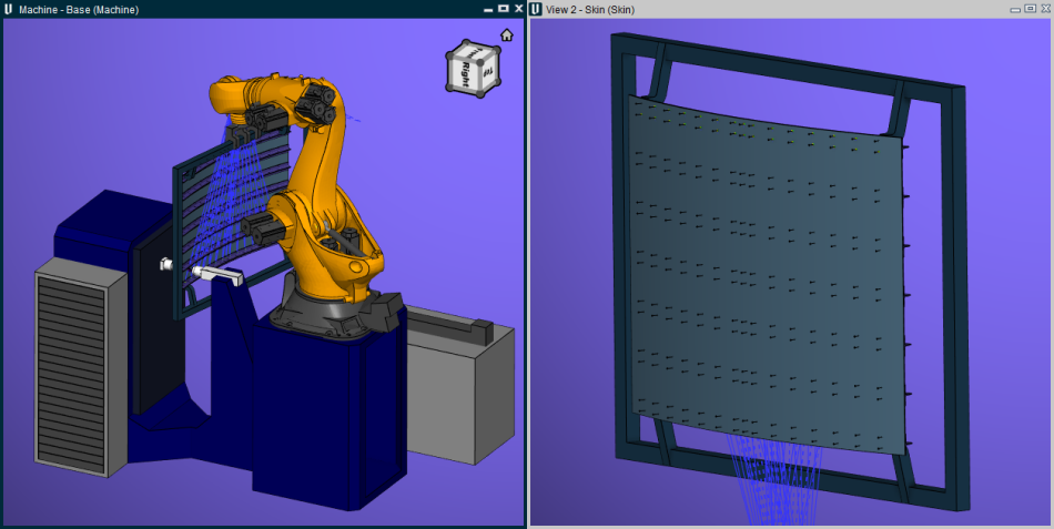
Vericut Composite Simulation Review Files
The Tape Path Display
As the NC program is replayed, the motion of the tape head is displayed in the Machine View in the graphics area.
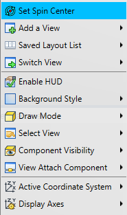
Right Mouse Button Feature Descriptions

Set Spin Center — Provides the same functionality as the Set Spin Center feature in the View Orient window.
Right-click on the position on an object (not the background) in the view where you want the spin center located, and then left-click on Spin Center in the menu that displays. The spin center will be located at your pick point.
Add a View — Use to add a view of the specified type. You can add as many views as desired.
Saved Layout List — Use to quickly select between previously stored layouts, capture new layouts, and edit existing layouts.
-
Capture Layout — Saves the current layout configuration for future reference.
-
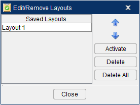
Edit/Remove Layouts — Opens the Edit/Remove Layouts window enabling you to manage your saved layouts. Select the view with your mouse or use the up/down arrows to highlight layouts. Activate will make the view active, Delete will remove the view, and Delete All will remove all views.
Switch View — Use to switch the view in the selected window with any other active window.
Enable HUD — Use to activated the HUD Control.
Background Style — Use to specify the background style for the view.
Draw Mode — Use to specify how machine components are displayed.
Select View — Orients the objects in the view to the selected view. The Select View feature list will contain all available standard and custom views.
Component Visibility — Use to make the selected component visible, or not visible, in a Machine view in the graphics area. The component list will contain all components in the current machine. A check indicates that the component is visible.
If the component list contains more than 32 items, Vericut Reviewer will automatically break up the list into sub-lists. Each sub-list will be identified by the first, and last, component in the list.
Attach Component — Attaches the view point and line of sight for a view to the selected component.
Active Coordinate System — Use to designate the "active" coordinate system. The "active" coordinate system applies to X-Caliper measurements and Section plane values.
This feature will display a list of available coordinate systems enabling you to select the desired CSYS from the list to be the “active” coordinate system. A check next to any of the coordinate systems in the Active Coordinate System list indicates the coordinate system is the “active” coordinate system.
You can display representations of these coordinate systems using the Display Axes feature described below.
Display Axes — Use to control when various axes and coordinate systems are displayed. A check next to any of the Display Axes features indicate that the feature is toggled "On" and the CSYS/axis will be displayed in the graphics area.
See the Shortcut in the NC Program Listing Area section for specific information on features Set Start through Goto End.
Vericut Graphics Area Right Mouse Button Shortcut Menus
Workpiece View
Right-click in Workpiece View in the Vericut Reviewer Graphics Area to display a menu with the following features:

See the Shortcut in the NC Program Listing Area section for specific information on features Set Start through Goto End.
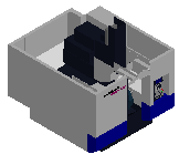
Machine View
Right-click in the NC Program Review Main Window, Machine View to display a menu with the following features:
See the Shortcut, in the NC Program Listing Area section above, for specific information on features Set Start through Goto End.
Profile View
Right-click in the NC Program Review Main Window, Profile View to display a menu with the following features:
See the Shortcut, in the NC Program Listing Area section above, for specific information on features Set Start through Goto End.
VCS Graphics Area Right Mouse Button Shortcut Menus
Machine View
Right-click in the NC Program Review Main Window, in a Machine View to display a menu with the following features:

See the Shortcut in the NC Program Listing Area section for specific information on features Set Start through Goto End.
Form View
Right-click in the NC Program Review Main Window, in a Form View to display a menu with the following features:
See the Shortcut in the NC Program Listing Area section for specific information on features Set Start through Goto End.
VDAF Graphics Area Right Mouse Button Shortcut Menus
Machine View
Right-click in the Vericut Reviewer Main Window, in a Machine View to display a menu with the following features:
See the Shortcut, in the NC Program Listing Area section above, for specific information on features Set Start through Goto End.
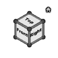
Vericut View Port Controls (View Cube)
The Vericut View Port controls, or View Cube, tracks the rotation of the view that is currently active in the Vericut Graphics area. Pan and Zoom have no effect on the cube. When you rotate the view in the graphics area, the cube rotates to the same orientation. Conversely, if you rotate the cube in the View Port control area, view in the graphics area will rotate to the same orientation.
The entire cube is a combination 26 buttons that are triggered by a left click. 12 edge views represented by the cylinders on the edges of the cube, 8 isometric views represented by 8 spheres at the corners of the cube and 6 standard views represented by the labeled sides of the cube. See the picture below.

Other features in the View Port Controls area enable you to specify view related characteristics. The  icon in the upper left corner of the View Port Controls area enable you to specify a view to represent a “home” view orientation that you can return to with a single mouse pick. It also enables you to specify the planar view that you want to represent the “Front” view.
The box in the lower left corner of the View Port Controls area enables you to specify the rotational increment that you want to use when rotating the cube and the view.
The box in the lower right corner of the enables you to capture, edit, and remove saved layouts.
Each of these features is shown in the picture above and is described in detail in the sections that follow.
Standard View Selection
A standard view is considered to be a planer view of the Front, Back, Top, Bottom, Left or Right. To change to a standard view, click on any visible plane on the cube. At that time the active View and the cube would rotate to that position and orientation so that the label is positioned parallel to the screen. The view would also be automatically centered and “Fit” in the active viewport.
To view the three non-visible sides, click on any standard view so that the arrows shown in the picture below become visible and then use them to rotate to the desired standard view.
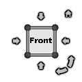
Click on the right facing arrow to rotate the cube and the view to the right. Click on the left facing arrow to rotate the cube and the view to the left. Similarly, click on the down facing arrow to rotate the cube and the view down. Click on the up facing arrow to rotate the cube and the view up.
Click on the left facing curved arrow in the upper right corner to rotate the current view counterclockwise. Click on the left facing curved arrow in the upper right corner to rotate the current view counterclockwise. Click on the right facing curved arrow in the upper right corner to rotate the current view clockwise.
By default, each time that you click on an arrow, the cube and the view will rotate 90 degrees. You have the ability to change the rotational increment. This will be described in the Changing the Rotational Increment section below.
Then select the desired view on the cube.
Non-standard View Selection
Non-standard views consist of Isometric views and Edge views. Isometric views are selected using the spherical corners of the cube. Edge views are selected using the cylindrical corners of the cube.
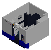
View Examples
In the following examples, the X indicates the pick location in the current position to get the Cube/View to the next rotated orientation. The  indicates the pick location at the end of the rotation.
| Cube | View | |
|---|---|---|
| Cube Initial | |
 |
| 1st Rotation | 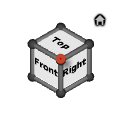 |
 |
| 2nd Rotation | 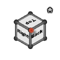 |
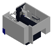 |
| 3rd Rotation | 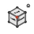 |
 |
Specifying a “Home” and a “Front” View
The (Home) icon enables you to specify the view that you want to be the “home” view. The “home” view should be the view that you most frequently display. Specifying a “home” view enables you to return to that view with a single mouse click.
The (Home) icon also enables you to specify the view that you want to represent the “Front” view as described in the Standard View Selection section above.
Right-click on the (Home) icon to display the following menu.
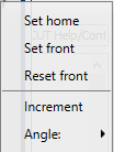
Set home — This feature enables you to set the current view as the “home” view. Once specified, this view is displayed whenever you left-click on the (Home) icon. Do the following to specify your “home” view.
-
Orient the current view to the view that you want to use as your “home” view.
-
Right-click on the
(Home) icon to display the menu above. - Left-click on the Set home option in the menu to designate that the current view is to be used for the “home” view.
Set front — This feature enables you to set the current view as the “Front” view. Once specified, this view is displayed whenever you Left-click on the “Front” face of the cube. Do the following to specify your “Front” view.
-
Orient the current view to the view that you want to represent the “Front” view.
-
Right-click on the
(Home) icon to display the menu above. - Left-click on the Set front option in the menu to designate that the current view is to be used for the “Front” view.
Reset front — Selecting the Reset front option in the menu caused the Cube/View to align itself with the Machine Origin coordinate system.
Changing the Rotational Increment
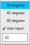
The box in the lower left corner of the View Port Controls area enables you to specify the rotational increment that you want to use when rotating the Cube/View. Right-click on the box in the lower left corner of the View Port Controls area to display the following menu.
-
30 degrees — When selected (checked) the cube and the view will rotate 30 degrees each time you click on an arrow in the “custom” rotation display in the View Port Controls area.
-
45 degrees — When selected (checked) the cube and the view will rotate 45 degrees each time you click on an arrow in the “custom” rotation display in the View Port Controls area.
-
60 degrees — When selected (checked) the cube and the view will rotate 60 degrees each time you click on an arrow in the “custom” rotation display in the View Port Controls area.
-
User input — Left-click on this feature and then use the text box immediately below it to manually enter your desired rotation angle.
The specified angle will be used each time you click on an arrow in the “custom” rotation display in the View Port Controls area.
📝 NOTE: “Non-default” rotation mode is only applicable to Standard View Selection. When using Non-standard View Selection features, the Cube/View will still rotate 90 degrees for each action.
You can return to “default” mode by left clicking on the triangle in the lower left corner of the View Port Controls area.
Dynamic Zoom, Pan, and Rotate
The Dynamic Zoom, Pan and Rotate features enable you to manipulate the displayed image of a view using a single mouse button.
| Function | Image | Explanation |
|---|---|---|
| Rotate |  |
Click with the left mouse button in a view and drag the mouse to rotate the display. |
| Pan |  |
Click with the right mouse button in a view and drag the mouse to rotate the display. |
| Zoom |  |
Rotate the thumb wheel while the cursor is in a view to zoom in or out on the display. Move the wheel toward you to make the displayed image larger. Move the wheel away from you to make the displayed image smaller. |
| Zoom to Box |  |
Press the thumb wheel down in a view and drag the mouse to define the box to zoom to. Release the thumb wheel to start the zoom. You can also click the thumbwheel to define the first corner of the box, and then move the mouse to the position defining the other corner of the box and click again. |
📝 NOTES:
-
Dynamic Controls (View tab > Dynamic Controls) must be set to Vericut.
-
The Shift key, Ctrl key, and mouse button combinations used in pre-V6.1 for view manipulation are still available.
- The Shift key, Ctrl key, and Arrow key combinations are no longer available.
- In NC Program Review, the dynamic rotate with the left button is briefly suspended when picking a rectangle for Settings > Display to Box.
Hot Keys
Reviewer can be controlled through hot keys. Each key is mapped to an action in Reviewer:
-
UP Arrow key: Step Forward
-
DOWN Arrow key: Step Backward
-
HOME key: Reset
-
END key: Set current to the end of program
-
Page UP key: Go to the beginning of current tool change
-
Page DOWN key: Go to the end of current tool change
Several quick key functions to enhance the interaction:
-
S: Set Start at the line where the cursor is
-
E: Set End at the line where the cursor is
-
C: Set Current at the line where the cursor is