MDI
Location: Home tab >  (MDI)
(MDI)
The MDI command button opens the MDI window which enables you to manually enter and process blocks of G-Code data. The MDI (Manual Data Input) function provides a quick and easy way of verifying that the machine/control combination responds to G-Code data commands as expected.
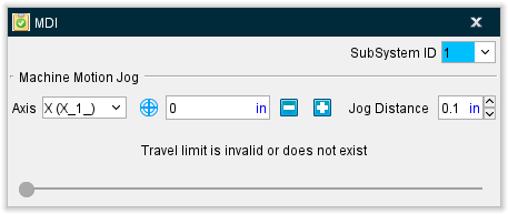
SubSystem ID — Use this feature to specify which machine subsystem the G-Code data command is to be applied to.
Machine Motion Jog
The Machine Motion Jog features enable you to incrementally jog the position of the Vericut machine in the same way that you can jog the real machine.
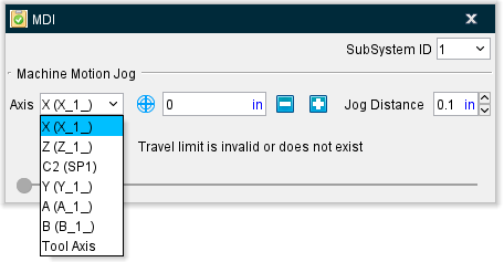
Axis — Indicates the current axis that the "Jog" feature will apply to. To change the current axis, simply select it from the pull-down list. The Axis list includes all of a machine’s moving axes as well as the Tool Axis. The name used for a particular Machine axis will be shown in parentheses as shown in the example below:
![]() (Machine CSYS) /
(Machine CSYS) / ![]() (Local CSYS) — This icon toggles between machine coordinate system and local coordinate system enabling you to specify the coordinate system that you want the Jog motion to be relative to. Left click on the icon to switch between modes.
(Local CSYS) — This icon toggles between machine coordinate system and local coordinate system enabling you to specify the coordinate system that you want the Jog motion to be relative to. Left click on the icon to switch between modes.
When in local coordinate system mode, it is assumed that the axis motion follows the format of “Axis + Position”. For example, if current axis is the “U” axis and its position is “10mm”, then the motion command is “U10”. If your control uses a different format than described above, an undesirable simulation will occur.
When in machine coordinate system mode, jog motion bypasses the control, so the local coordinate is not updated. When you switch from machine coordinate system mode to local coordinate system mode while jogging, the previous “local” position in the control will be used, which does not reflect the current local position.
The current axis position (linear or rotary), with respect to the Axis "zero" position, is displayed in text field next to Axis.
Use the ![]() (increase) and
(increase) and ![]() (decrease) buttons to jog the machine the specified "Jog Distance" each time you press them. You can also press and hold the button down to repeatedly move the specified distance.
(decrease) buttons to jog the machine the specified "Jog Distance" each time you press them. You can also press and hold the button down to repeatedly move the specified distance.
Jog Distance — Use to set the distance the axis position will move by a single click on increase/decrease buttons.
📝 NOTE: Moving the machine axes with Machine Motion Jog will not produce a block in the NC Blocks table until the Save Location as NC Block button is pressed.
Machine Travel Limits Slider
The Machine Travel Limits Slider enables you to move a specified machine axis through the entire range of travel. As you move the slider in the MDI window, you will see the specified axis moving in a Machine view in the graphics area. Collisions will be displayed in the graphics area. Collision and other error messages will be displayed in the Logger.
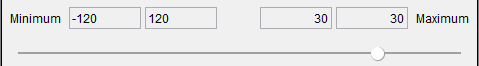
The numbers in the four boxes, from left to right, represent the following:
-
The value of the Minimum Travel Limit
-
The distance between the Minimum Travel Limit and the current axis position.
-
The distance between the Maximum Travel Limit and current axis position.
-
The value of that Maximum Travel Limit.
The Minimum and Maximum Travel Limit values are automatically set for the selected axis based on the travel limit settings on the Machine Settings window: Travel Limits tab (see Vericut Help for more information).
The axis that you want to move is specified using the Axis feature describe above in the Machine Motion Jog Section.
Use the slider to move the specified axis. You can click on the slider and drag it to the left (toward the Minimum travel limit) or to the right (toward the Maximum travel limit). You can also click on the slide bar to the left (toward the Minimum travel limit) of the slider or click on the slide bar to the right (toward the Maximum travel limit) of the slider. Each time that you click on the slide bar, the slider will move approximately 10% of the total distance between the travel limits in the selected direction.
The slider will become disabled in the following situations:
-
The travel limit specified for the axis on the Machine Settings window: Travel Limits tab is invalid or does not exist
-
Travel limit record, on the Machine Settings window: Travel Limits tab, for the specified axis has the Ignore option is toggled “on” (checked).
-
The specified axis is the Tool Axis.
-
In each situation, the row above the slider (with the four boxes) will be replaced with a message explaining the reason why the slider is disabled.