Fastener Summary (VDAF Reviewer Only)
Location: Home tab >  (Fastener Summary)
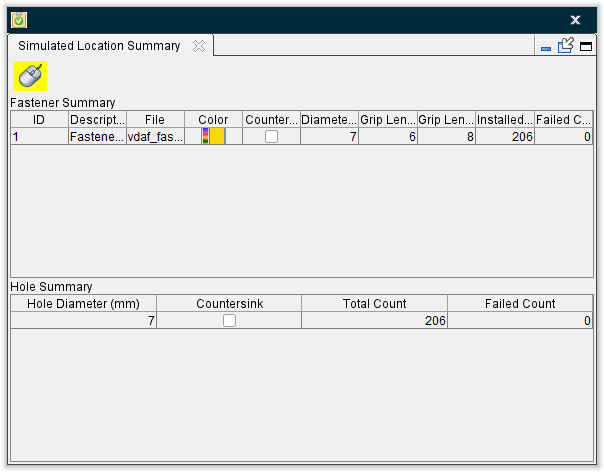
The Fastener Summary command button is used to open the Simulated Location Summary panel, which consists of two tables of information associated with the simulation. The Fastener Summary table provides information about the fasteners that have been inserted during the simulation. The Hole Summary table provides information specific to holes drilled during the simulation.
The Simulated Location Summary panel is one of the dockable panels enabling you to dock it inside the Vericut Drill and Fastener Simulation main window if you choose. See Dockable Panels section of Vericut Reviewer Help for additional information.
📝 NOTE: When the Simulated Location Summary panel is docked, make sure that you click in the panel so that it becomes the "active" panel before using F1 to get help specific to the panel. Otherwise F1 will go to the Vericut Help Library.
 (Close) — Located at the end of the tab, this icon enables you to close the Simulated Location Summary panel.
 (Close) — Closes the Simulated Location Summary panel. This icon is only displayed when the Status panel is not docked.
Simulated Location Summary window features
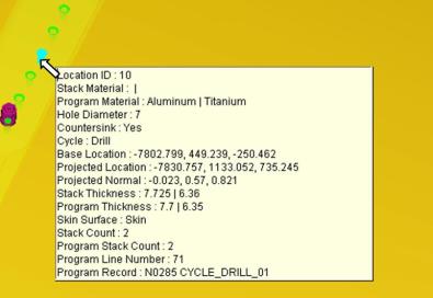
 (Mouse Pick Indicator) — When highlighted, the Mouse Pick Indicator indicates that the Simulated Location Summary panel is the "active" window. When highlighted, holding the cursor over a drilled hole/fastener location, in the graphics window, will highlight the location and display information specific to the particular location as shown in the picture below.
(Close) — Closes the Simulated Location Summary window.
Fastener Summary Table — The Fastener Summary table provides information about the fasteners that have been inserted during the simulation. Each row in the table represents a summary of the following information for a specific fastener.
ID — the fastener's ID.
Description — the description of the fastener
File — the filename of the Fastener Model file
Color — the color of the fastener
Countersink — indicates whether or not the fastener requires a countersunk hole. A check indicates that a countersunk hole is required.
Diameter — the diameter of the fastener
Grip Length Min. — the minimum grip length value of the fastener
Grip Length Max. — the maximum grip length value of the fastener
Installed Count — the number of fasteners installed during the simulation
Failed Count — the number of fastener installations that failed during the simulation.
Hole Summary Table — The Hole Summary table provides information specific to holes drilled during the simulation. Each row in the table represents a summary of the following information for a specific drilled hole size.
Hole Diameter — the diameter of the drilled hole
Countersink — indicates whether or not the drilled hole has been countersunk. A check indicates a countersunk hole.
Total Count — the total number of holes that were drilled during the simulation
Failed Count — the number of hole drilling operations that failed during the simulation.
💡 Tips:
-
You can change the position of a column by clicking in the column header and drag the column to the right, or left, to the desired position.
-
You can change the width of each column by clicking on the divider between headers and then moving the divider to the left or right to make the column width smaller or larger.