View Axes (View Axes window)
Location: View tab > ![]() (Axes)
(Axes)
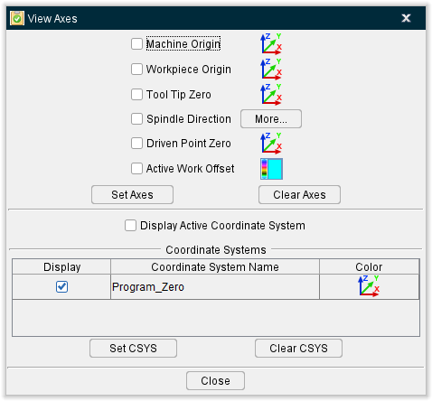
The Axes command button opens the View Axes window enabling you to control when various axes and coordinate systems are displayed. Axes are created by Vericut Reviewer and are stored in the Preferences file. Coordinate Systems (CSYS) are user defined and are stored in the "setup". Once displayed, axes and coordinate system symbols remain displayed until toggled "Off" in the View Axes window. Solid lines indicate that an axis is parallel or pointing out of the screen. Dashed lines indicate that an axis is pointing into the screen.
↘️ Shortcut: You can also change axes displayed by right-clicking in the view, and selecting from the Display Axes list in the menu that displays. See the Graphics Area, Right Mouse Button Shortcut Menus section of Vericut Reviewer Help for more information.
AXES
Use the Color Palette icons  , to specify a "global" display color for each type of axis described below.
Component — When selected, displays XYZComponent axes that representing the coordinate system of a component. Each component has its own local coordinate system.
Model — When selected, displays XYZModel axes that represent the coordinate system of a model. Each model has its own local coordinate system.
Machine Origin — When selected, displays XYZMachine Origin axes that represent the coordinate system in which an NC machine is defined.
Workpiece Origin — When selected, displays XYZWorkpiece Origin axes that represent the coordinate system to which Stock, Fixture, and Design components are connected.
-
In a simulation where a machine IS NOT defined, such as when processing APT-CLS NC program files, the workpiece coordinate origin is the origin of the non-moving "Base" component to which Stock, Fixture, and Design components are connected.
-
In a simulation where a machine IS defined, such as when processing G-Code NC program files, the workpiece coordinate origin is the origin the machine component responsible for carrying the Stock, Fixture, and Design components.
📝 NOTE: The Workpiece Origin axes are not available in the Vericut Composite Simulation View Axes window.
Tool Tip Zero — When toggled "On", displays the XYZToolTip axes that represent where the tool tip (the Vericut control point) of the "active" tool would be located, relative to the "active" stock, if all linear axes were positioned at zero. The display is based on the actual Machine/Control configuration and therefore may be displayed as a right hand axis, a left hand axis or possibly even a non-orthogonal axis. If no tool has been loaded, Vericut assumes a zero length tool.
The following should be considered when using this feature:
-
Tool Tip Zero is only applicable when processing G-Code Data.
-
The Tool Tip Zero display is based on the "active" tool. If the machine being used has more than one tool component, the correct tool component must be set as active before valid results can be achieved.
- The Tool Tip Zero display is based on the "active" stock. If more than one stock component on the machine, the correct stock component must be set as active before valid results can be achieved.
- The Tool Tip Zero display shows where the tool tip is and therefore may not be particularly useful when programming a 5-axis machine in "gage-length" mode.
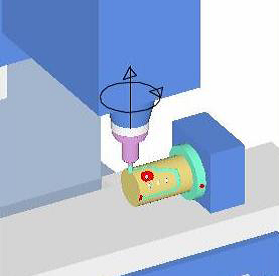
Spindle Direction — When toggled "On", a graphic is displayed indicating direction that the spindle is turning.
| Mill Example | Lathe Example |
|---|---|
 |
 |
The Spindle Direction indicator can also be turned On/Off by right-clicking in the graphics window and selecting Display Axes > Spindle Direction from the pop-up menu that displays. Note that only the center arrow displays until the spindle is turned on in the NC program.
Driven Point Zero — When toggled "On", displays the "driven point" (identified by the ![]() symbol) and the XYZDriven Point Zero axes.
symbol) and the XYZDriven Point Zero axes.
The "driven point" is only displayed in the Machine View. Depending on the machine configuration, more than one Driven Point Zero axis may be displayed in the View Axes window as shown in the picture above.
The initial "driven point" position is determined based on the following:
- If the macro PivotOffsetCompName has been called, the initial driven point is the origin of this component, otherwise
-
If there are no rotary/turret components attached to the "active" tool component, the initial driven point is the origin of the "active" tool component.
-
If there are 1, or more, rotary/turret components attached to the "active" tool component, the initial driven point is the origin of the highest level rotary/turret component.
The following offsets are then applied to the initial "driven point" (adjusted as needed for RTCP):
-
Gage Offset
-
Tool Nose Compensation Offset
- Tool Length Compensation Offset
- Turret Offset
- Gage Pivot Offset
- Pivot Offset (RTCP)
- 3D Tool Length Comp Offset (Fanuc)
The Driven Point Zero axes represent where the driven point of the "active" tool would be located, relative to the "active" stock, if all linear axes were positioned at zero. The display is based on the actual Machine/Control configuration and therefore may be displayed as a right hand axis, a left hand axis or possibly even a non-orthogonal axis. The Driven Point Zero axes are displayed in Workpiece and Machine views.
The following should be considered when using this feature:
-
Driven Point Zero is only applicable when processing G-Code Data.
-
The Driven Point Zero display is based on the "active" tool. If the machine being used has more than one tool component, the correct tool component must be set as active before valid results can be achieved.
- The Driven Point Zero display is based on the "active" stock. If more than one stock component on the machine, the correct stock component must be set as active before valid results can be achieved.
- Some machine configurations do not conform to initial "driven point" rules described above and therefore will not produce useful results. An example of this would be Maho-Phillips machines using a two position head. The initial driven point could not be calculated correctly resulting in invalid results.
- Dual turret machines typically will not have the active tool defined for both turrets; therefore the initial driven point cannot be calculated correctly resulting in invalid results.
- Some machine/controller combinations, like the one in the sample file bos5vm01.VcProject, may not produce the results that you might expect, but based on the above definitions, the displayed results are accurate.
Set Axes — When selected, all "axes" are toggled "On" and will be displayed.
Clear Axes — When selected, all "axes" are toggled "Off" and will not be displayed.
📝 NOTES:
-
Axes display status is stored in the Preferences file. Axes that are displayed when exit a Vericut Reviewer session are displayed the next time you run Vericut Reviewer.
-
Axes are drawn in the Foreground color by default. Use the Color Palette icon
, for each axis type to change the display color of the individual axes.
COORDINATE SYSTEMS (CSYS)
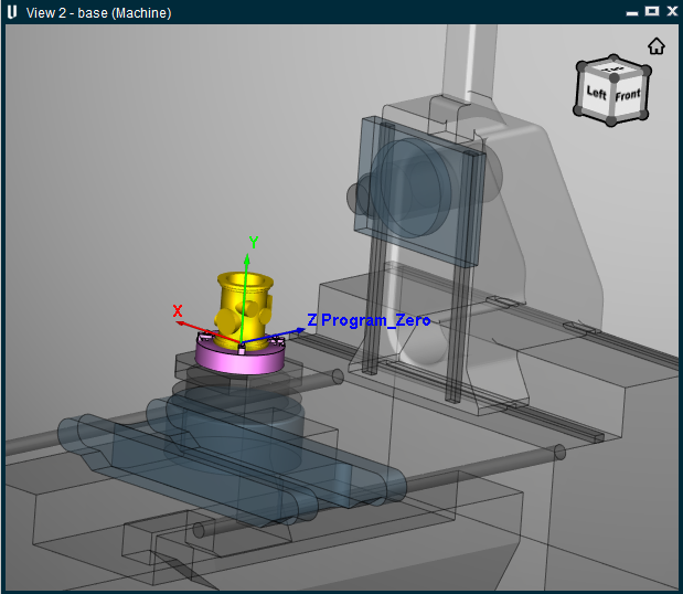
Display Active Coord. Sys. — When toggled "On", a coordinate system with the name of the active coordinate system will display in the Vericut Reviewer graphics area as shown below. Only the "active" coordinate system will display with the marker at its origin as shown.
Coordinate System Table — The Coordinate System Table displays all coordinate systems defined for the "current setup". Each CSYS in the table has a checkbox that toggles "On" and "Off", indicating whether it is displayed or not. By default, CSYS are drawn in the Foreground color. The color of the CSYS can be changed using the Color Palette button, described below. The background color of each Coordinate System Name field indicates the color that the CSYS will be displayed.
Set CSYS — When selected, all "coordinate systems" are toggled "On" and will be displayed.
 (Color Palette button) — Use to define the display color for a "coordinate system". To specify a color for a particular CSYS, click on the Coordinate System Name field, in the Coordinate System Table, so that it becomes highlighted. The background color of the Coordinate System Name field indicates the current color of the CSYS. Click on the Color Palette button and select the desired color from the color palette that displays.
Clear CSYS — When selected, all "coordinate systems" are toggled "Off" and will not be displayed.
📝 NOTES:
-
Coordinate System display status is stored in the "setup".
-
Axes are drawn in the Foreground color by default. Use the Color Palette button
, in the Coordinate Systems section of the View Axes window to change the display color of individual coordinate systems.