View tab
The View tab contains features for manipulating how the Graphics Area displays simulated material including buttons for adding or removing views, dynamic zooming and rotating, resolution control, translucency settings, and more. All features will be summarized on this page but each hyperlinked feature can be clicked on to see a more detailed description for more information.
Layout group
-
Add View — Creates a new view in the Graphics Area. See Layout (View) section for more detail on adding views.
-
Delete View — Removes the current active view from the Graphics Area. See Layout (View) section for more detail on deleting views.
-
View to Back — Moves the "active" view to the back. This function can also be accessed using the right mouse button in the active view.
-
View to Front — Moves the selected view to the front. Selecting "View to Front" displays a list of all available views allowing you to select the desired view to be moved to the front even if it is obscured by other views in the graphics area.
-
Always in Front — Makes the active view remain "always in front" until it is specifically moved to the back or until another view is specified as "always in front". This function can also be accessed using the right mouse button in the active view.
-
Single View Layout — If multiple views are open, eliminates every view except the active one. If no views are open, generates a new view.
-
Two View Layout (Horizontal) — Generates two views, a Workpiece view and a Machine view, placed side by side.
-
Two View Layout (Vertical) — Generates two views, a Workpiece view and a Machine view, placed one on top of the other.
View group
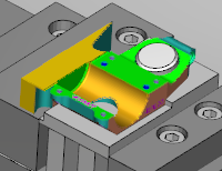
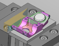
- Stock/Design View — This button displays translucent Stock and solid Design, regardless of the component translucency settings. When the user clicks out of this temporary view state, then the component/model visibility goes back to what it was before that option was engaged. This feature is only available when Reviewer is processing a Vericut Simulation file.
| Normal | With Stock/Design View active |
|---|---|
 |
 |
- Section — This button opens the Section window which has features that enable you to define section planes through a Vericut model in a Workpiece view.
- Lock Spin Center — This button sets a spin center around which machines and profiles can be rotated.
- View Orthogonal— This button snaps the current view to the closest orthogonal view.
-
Reverse— This button reverses the current view.
-
Attributes— This button opens the View Attributes window enabling you to control the attributes of a view, such as: what is seen in a view, light source, shading, etc.
-
Orient — This button opens the View Orient window enabling you to orient the view (e.g. rotate, zoom, pan, reverse, etc.).
-
Resolution — controls the quality of cut model display. Increasing resolution displays a more accurate representation of the cut model, and requires more computer resources and processing time to display and manipulate the model. A coarse display resolution is automatically used when dynamically manipulating the model, such as rotation, zooming, etc. When the dynamic action is finished, the display is upgraded to the previous resolution. Options:
-
Manual — A display resolution which allows most models to be manipulated with acceptable performance and display quality.
-
Auto — Automatically sets display resolution based on viewing distance from the model. Resolution automatically increases when you zoom closer to see details on the model, and decreases as you zoom out.
Zoom/Fit group
-
Zoom In — Increases the size of the model.
-
Zoom Out — Decreases the size of the model.
-
Zoom to Box — Use the mouse to highlight an area of the View that will be zoomed to.
-
Zoom Box in New View — Use the mouse to highlight an area of the View that will be zoomed to. This will open the zoomed in view in a new View window.
-
Fit — Fits the model of the currently highlighted window so that the model fills the entire view.
-
Fit All — Fits every model in every View window so that the models fill every window.
Dynamic group
-
Dynamic X Rotation — Once selected, enables you to rotate the View along the X axis by holding down the mouse button.
-
Dynamic Y Rotation — Once selected, enables you to rotate the View along the Y axis by holding down the mouse button.
-
Dynamic Z Rotation — Once selected, enables you to rotate the View along the Z axis by holding down the mouse button.
-
Dynamic XY Rotation — Once selected, enables you to rotate the View along the X and Y axes simultaneously by holding down the mouse button.
-
Dynamic Pan — Once selected, enables you to move the model up, down, left, and right by holding down the mouse button. This functionality can also be used by holding down the right-mouse button without selecting Dynamic Pan.
-
Dynamic Zoom — Once selected, enables you to zoom in and out by holding the mouse button down. Moving the cursor up zooms in, moving down zooms out.
Display group
-
View Type — use this pulldown to select View Type.
-
Background Style — use this pulldown to select Background Style.
-
Draw Mode — use this pulldown to select Draw Mode.
-
Spun Tool Display — When on (highlighted), tools in the Tool Display Area will appear as they would when they are in use. This feature will remain active until it is toggled off (not highlighted) or until you exit Vericut Reviewer. Spun Tool Display is off by default at the start of each Vericut session. This feature is only available when Reviewer is processing a Vericut Simulation file.
-
Spun Part Display — When on (highlighted), the way in which tools spin will be displayed. This feature will remain active until it is toggled off (not highlighted). This feature is only available when Reviewer is processing a Vericut Simulation file.
-
Ambient Occlusion — When active, approximates how bright light should be shining on specific surface parts.
-
Refine Display — Improves the quality of the image on screen. This feature is only available when Reviewer is processing a Vericut Simulation file.
-
Axes — Opens the View Axes window enabling you to control the CSYS. This feature is only available when Reviewer is processing a Vericut Simulation file.
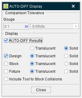
- AUTO-DIFF — If the Review file contains the option to use AUTO-DIFF, the button will display in color. This button opens the AUTO-DIFF window enabling you to see the AUTO-DIFF results captured from Vericut at the time of saving the Review file. If the Review file was saved without AUTO-DIFF results, then the button will be grayed out and can't be used. This feature is only available when Reviewer is processing a Vericut Simulation file. Use the AUTO-DIFF window to toggle on or off the display and translucency of Design, Stock, and Fixture elements. You can also toggle on or off Include Tool to Stock Collisions.
Translucency group
The Translucency Slider controls how translucent the display components will be. Slide the slider all the way to the left to make the view completely transparent and slide the slider all the way to the right to make the view completely opaque.
Apply To All Views — Toggle this feature on (checked) to apply translucency settings to all views, otherwise translucency settings will only be applied to the currently active view.