Common Features
The following features are common the X-Caliper window for review files created in Vericut Simulation, Vericut Composite Simulation, or Vericut Drill and Fastener Simulation.
X-Caliper Measurements in Vericut Logger
The X-Caliper tab command buttons are used to take measurements, and obtain historical and mathematical information about Vericut models. Measurements are displayed in the Vericut Logger, X-Caliper Measurement tab. The appearance of the X-Caliper Measurement tab will vary depending on the X-Caliper feature being used. X-Caliper shows what is being measured on the model area by highlighting the "measure from" point (+) and the "measure to" point (o). Measurements are described relative to the active coordinate system.
X-Caliper window - Vericut Simulation Review file
📝 NOTE: Machined features can only be measured in a workpiece view.
X-Caliper window - Vericut Composite Simulation Review file
X-Caliper window - Vericut Drill and Fastener Simulation Review file
Model Thickness
Location: X-Caliper tab >  (Thickness)
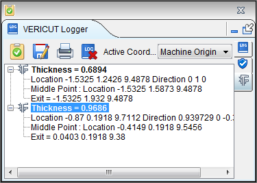
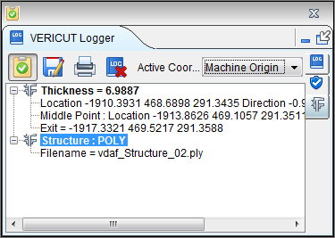
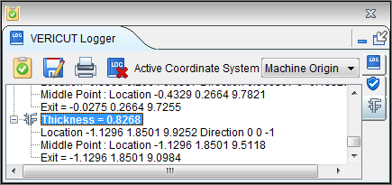
The Model Thickness command button is used to measure solid stock material.
Sample Vericut Logger panel, X-Caliper tab results:
Location — Represents the XYZ coordinates of the point to measure from.
Direction — Represents IJK of the measurement direction vector into material.
Data from the screen pick fills the Location and Direction data fields. If needed, you can edit data in these fields, and then press Measure to obtain a measurement.
Measurement results are displayed in the X-Caliper window. Data output includes the Location and Direction values input, the XYZ point where the direction vector exits the material and the measured thickness between the Location and Exit points.
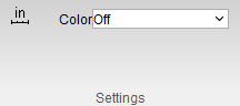
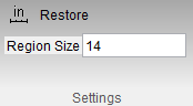
When Model Thickness is selected, the Settings group changes to the following:
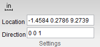
The Location and Direction text boxes can be manually edited.
Air Distance
Location: X-Caliper tab >  (Air Distance)
The Air Distance command button is used to measure air gap between two solid surfaces.
Sample Vericut Logger panel, X-Caliper tab results:
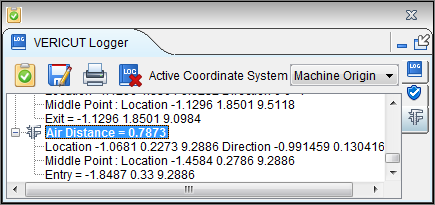
Location — Represents the XYZ coordinates of the point to measure from.
Direction — Represents IJK of the measurement direction vector away from solid material.
Data from the screen pick fills the Location and Direction data fields. If needed, you can edit data in these fields, and then press Measure to obtain a measurement.
Measurement results are displayed in the X-Caliper window. Data output includes the Location and Direction vector values input, the XYZ point where the direction vector re-enters solid material and the measured air distance between the Location and Entry points.
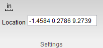
When Air Distance is selected, the Settings group changes to the following:
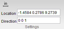
The Location and Direction text boxes can be manually edited.
Plane to Point
Location: X-Caliper tab >  (Plane to Point)
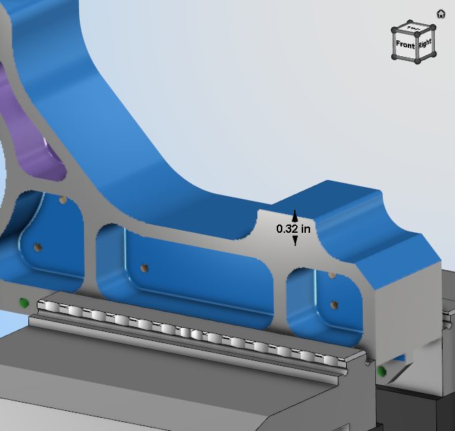
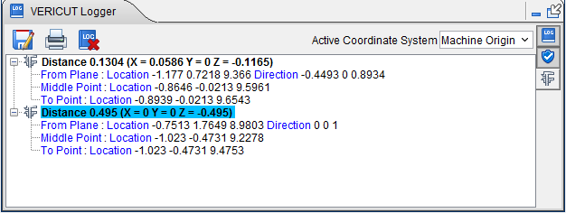
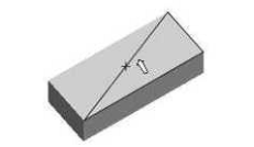
The Plane to Point command button enables you to select two points on a material to analyze the distance between them. Once the command button is active, click in the graphical display on the first point and the second point you wish to measure between. Notice that a blue arrow will point outwards from the plane you are selecting, helping you to make certain you are selecting the right plane. The information will be displayed in your Logger as shown below:
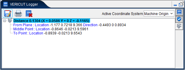
Additionally, the distance measurement will then be superimposed on the material at the point where the measure was taken in the View window as shown below:
This measurement will display only so long as any of the group command buttons are active. All measurements will disappear once none of these buttons are active but the measurements can be viewed again by turning on one of these command buttons. This feature can also be edited by left-clicking on the measurement thus displaying the following menu:
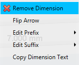
Remove Dimension — clicking the red x deletes the measurement permanently.
Edit Prefix — use this feature to edit in text that will appear before the measurement via a text edit window. Click Default on the edit window that appears to remove entered text.
Edit Suffix — use this feature to edit in text that will appear after the measurement via a text edit window. Click Default on the edit window that appears to remove entered text.
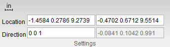
When Plane to Point is selected, Setting group changes to the following:
Plane Angle
Location: X-Caliper tab >  (Plane Angle)
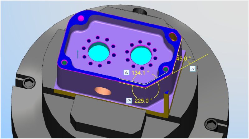
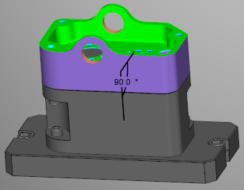
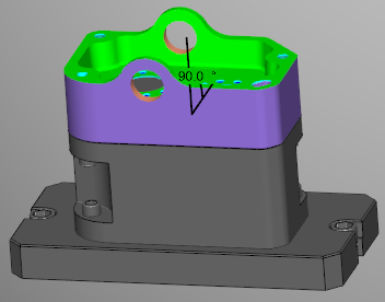
The Plane Angle command button enables you to select two points on a material to analyze the angle between them. Once the command button is active, click in the graphical display on the first point and the second point you wish to measure between. Notice that a blue arrow will point outwards from the plane you are selecting, helping you to make certain you are selecting the right plane. The information will be displayed in your Logger as shown below:
Additionally, the angle measurement will then be superimposed on the material at the point where the measure was taken in the View window as shown below:
This measurement will display only so long as any of the group command buttons are active. All measurements will disappear once none of these buttons are active but the measurements can be viewed again by turning on one of these command buttons. This feature can also be edited by left-clicking on the measurement thus displaying the following menu:
Remove Dimension — clicking the red x deletes the measurement permanently.
Edit Prefix — use this feature to edit in text that will appear before the measurement via a text edit window. Click Default on the edit window that appears to remove entered text.
Edit Suffix — use this feature to edit in text that will appear after the measurement via a text edit window. Click Default on the edit window that appears to remove entered text.
Axis to Axis
Location: X-Caliper tab >  (Axis to Axis)
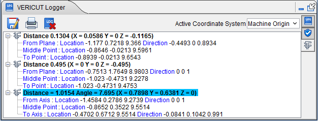
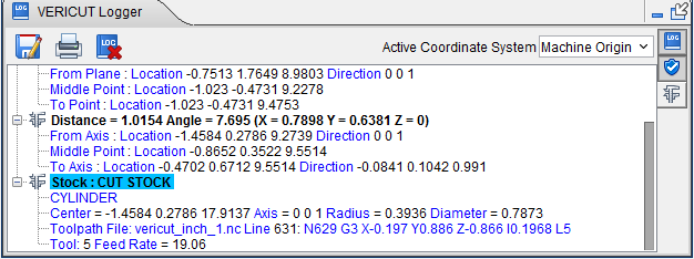
The Axis to Axis command button enables you to select two points on a material to analyze the distance between parallel holes. Once the command button is active, click in the graphical display on the first point and the second point you wish to measure between. Notice that a blue arrow will point outwards from the center of the hole you are selecting, helping you to make certain you are selecting the right plane. The information will be displayed in your Logger as shown below:
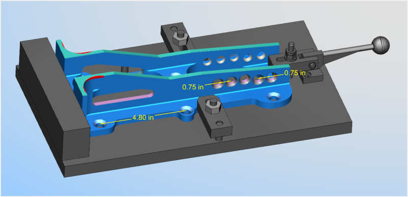
Additionally, the distance measurement will then be superimposed on the material at the point where the measure was taken in the View window as shown below:
This measurement will display only so long as any of the group command buttons are active. All measurements will disappear once none of these buttons are active but the measurements can be viewed again by turning on one of these command buttons. This feature can also be edited by left-clicking on the measurement thus displaying the following menu:
Remove Dimension — clicking the red x deletes the measurement permanently.
Edit Prefix — use this feature to edit in text that will appear before the measurement via a text edit window. Click Default on the edit window that appears to remove entered text.
Edit Suffix — use this feature to edit in text that will appear after the measurement via a text edit window. Click Default on the edit window that appears to remove entered text.
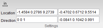
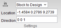
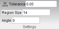
When Axis to Axis is selected, Setting group changes to the following:
Diameter/Radius
Location: X-Caliper tab >  (Diameter/Radius)
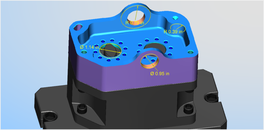
The Diameter/Radius command button enables you to select any point on the wall of a cylinder or hole to analyze the distance from that point to the opposite end wall of the cylinder or hole. Once the command button is active, click in the graphical display on the point you wish to measure from. Notice that a blue arrow will point outwards from the selection point towards the wall it will be measuring towards, helping you to make certain you are selecting the right plane. The information will be displayed in your Logger as shown below:
Additionally, the distance measurement will then be superimposed on the material at the point where the measure was taken in the View window as shown below:
This measurement will display only so long as any of the group command buttons are active. All measurements will disappear once none of these buttons are active but the measurements can be viewed again by turning on one of these command buttons. This feature can also be edited by left-clicking on the measurement thus displaying the following menu:
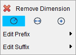
Remove Dimension — clicking the red x deletes the measurement permanently.
Radius — select this option to measure from the center of the circle to the edge.
Diameter — select this option to measure from one end of the circle to its opposite end.
Center — select this option to measure the exact middle of the circle.
Edit Prefix — use this feature to edit in text that will appear before the measurement via a text edit window. Click Default on the edit window that appears to remove entered text.
Edit Suffix — use this feature to edit in text that will appear after the measurement via a text edit window. Click Default on the edit window that appears to remove entered text.
Distance/Angle
Location: X-Caliper tab > Distance/Angle group
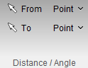
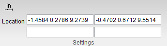
The Distance/Angle command buttons are used to measure the distance and/or angle between any combination of two points, planes, conic axes, model or component origins, or edges formed by intersecting planes or cylinders. In general, select the "From" feature, then select the "To" feature. X-Caliper shows what is being measured on the model by highlighting the "measure from" point (+) and the "measure to" point (o) as well as a line representing the distance (or vectors representing the angle) between them.
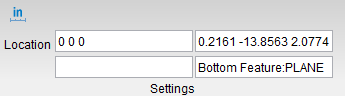
Sample Vericut Logger panel, X-Caliper tab results:
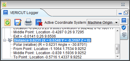
📝 NOTE: Machined features can only be measured in a workpiece view.
From / To groups — Each group includes the Feature, Location and Direction used to specify what to measure from and what to measure to. Use the From / To arrows ![]() , to control which fields are filled in by screen pick data. You can select features on the Vericut model, or enter number values (separated by blank spaces) directly into the fields. After selecting the From feature, Vericut automatically transfers control to the To group. After selecting the To feature the X-Caliper window displays the measurement data.
, to control which fields are filled in by screen pick data. You can select features on the Vericut model, or enter number values (separated by blank spaces) directly into the fields. After selecting the From feature, Vericut automatically transfers control to the To group. After selecting the To feature the X-Caliper window displays the measurement data.
-
Feature — Controls the types of features to measure between. Select the Feature type from the pull-down list. Feature descriptions:
-
Point — The X, Y, Z of the pick point or entered point coordinates.
-
Plane — A flat, unbounded surface. If a curved surface is selected, data retrieved represents a plane tangent to the selected model surface at the pick point.
-
Axis — Centerline of a cylinder or conic.
-
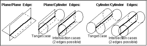
Edge — Edge formed by two intersecting planes or parallel cylinders. Special cases follow.
-
Plane/Cylinder edge — Only a cylinder with an axis parallel to the plane can produce an edge. Tangent conditions produce 1 edge. Intersecting conditions produce 2 possible edges, thus the one closest to the cylinder pick-point is used.
-
Cylinder/Cylinder edge — Only cylinders with parallel axes can produce an edge. Tangent conditions produce 1 edge. Intersecting conditions produce 2 edges, thus the one closest to the last cylinder pick-point is used.
-
Vertex — Enables you to easily select one of the six key points associated with the triangles representing the faces of a model. For each triangle, the points consist of the three vertices and the midpoint of each of the triangle's three sides. Vericut selects the point closest to your mouse pick. If the mouse pick is over the cut stock, Vertex works in the same way as the Point feature described above.
Vertex is a useful tool for measuring the trace of tool/fixture collisions on uncut fixtures. -
Model Origin — Origin of a selected model. Use the View tab > Axes function to see model origin axes.
-
Component Origin — Origin of a selected component. Use the View tab > Axes function to see component origin axes.
-
CSYS Origin — Origin of the selected coordinate system axis. Use the View tab > Axes function to display the coordinate systems that are available.
-
CSYS Axis — The X, Y, or Z axis of the selected coordinate system. Use the View tab > Axes function to display the coordinate systems that are available.
-
Circle Center — Use this feature to specify a circle center point to be used as a From or To feature.
-
Choose Circle Center from the pull-down list, and then click the arrow
 to enable selecting geometry in the graphics area.
Follow the prompts in the temporary message area at the bottom of the logger to define the circle center point. -
Pick the XY plane of the circle.
- Pick the cylinder/cone face that contains the circle.
The circle center point will display in the graphics area and the coordinates of the center point will display in the Location text field in the X-Caliper window.
-
-
Location — Represents the XYZ coordinates of the screen pick.
-
Direction — Represents IJK of the normal vector at the location of the screen pick.
Data from the screen pick fills the Location and Direction data fields in the active From or To group. If needed, you can edit data in these fields, and then press Measure to obtain a measurement.
Measurement results are displayed in the X-Caliper window. Data output includes the From / To values input and the measured distance and/or angle.
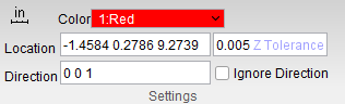
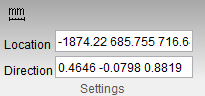
When Distance/Angle is selected, the Settings group changes to the following:
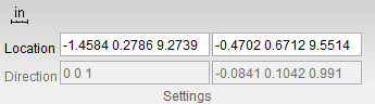
The location text boxes can be used to manually input location data.
Settings group
Location: X-Caliper tab > Settings group
The X-Caliper tab Settings group contains additional information and command buttons for managing X-Caliper features. The default display for the Settings group is as follows:

![]() /
/![]() (Inch/Millimeter) — This option is used to specify whether measurement will be in inches or in millimeters. Clicking on the icon changes it from
(Inch/Millimeter) — This option is used to specify whether measurement will be in inches or in millimeters. Clicking on the icon changes it from![]() to
to ![]() and back. When
and back. When ![]() is displayed, the program will measure in inches. When
is displayed, the program will measure in inches. When ![]() is displayed, the program will measure in millimeters.
is displayed, the program will measure in millimeters.
The Settings group changes depending on which feature from the X-Caliper tab is selected. For Vericut files: Scallop does not change the Settings group. For VCS files: Information, Stack Thickness, Tow Packet, and Stagger do not change the Settings group. For VDAF files: Information does not change the Settings group. For all other features, the Settings group changes to the following:
For Vericut Files:
Feature/History –
Closest Point –
Volume –

Stock/Design Distance –
Center of Gravity –
Highlight Same Plane –
Hole Depth –
C-Sink Depth –
For VCS Files:
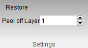
Peel off Layer –
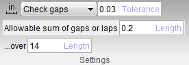
Couse Gap/Overlap –
Steering Radius –
Fiber Direction –
For VDAF Files:
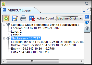
Stack Thickness –
All of these relative features of the Settings group will be explained in their relevant feature sections.
Dimensions group
Location:
X-Caliper tab > Dimensions group
The X-Caliper Dimensions group command buttons are used to control saving X-Caliper measurements as they are taken. These command buttons are used to generate and remove Dimension labels as needed. Once a label has been created, it will appear in the View window as a block of text with a plus sign (+) indicating where the label was created.
Display Labels — this feature is used to specify how X-Caliper measurements will be saved. Toggle this feature on (checked) to be able to display labels . By choosing an option in conjunction with the Feature/History command button, labels of information can be saved. These labels can be moved around the View window by left-clicking and dragging the label to a new location. You can also press the Delete key on your keyboard to remove the last dimension label that was added.
 Remove All Dimensions — removes all labels that have been collected, regardless of whether they have been selected.
 Add Unattached Notes — Adds a floating note to be edited with whatever information you desire to input. To create a note, drag your mouse diagonally in a view to create the note text box. Type the desired text into the box and then resize or move the box around as desired. While still in edit mode, you can delete the note or switch between attached and unattached notes. Click outside of the box when you are finished to set the note.
 Add Attached Notes — Adds a note with a line pointing to a specific location where the note will be located. To create a note, drag your mouse diagonally in a view to create the note text box. Type the desired text into the box and then resize or move the box around as desired. While still in edit mode, you can delete the note or switch between attached and unattached notes. Click outside of the box when you are finished to set the note.
Text Display — To change the color for the labels feature, click on the  (Color Palette) icon to display the color palette window shown below.
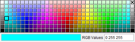
Click on a color in the color palette window, to specify the color for the label feature. The color palette window will close and the right side of the  (Color Palette) icon in the Dimensions group will update to reflect the selected color.
To close the color palette window without changing the color, click on the ![]() in the upper right corner of the color palette window.
in the upper right corner of the color palette window.
Additionally, there is a number field next to the color palette icon which can be used to specify the font size of the label.
 Extra Settings — this feature opens the Label Settings window which enables you to control the information displayed by default for measurement labels. Changing settings in this window are effective for subsequent measurements. Settings are saved to your Preferences file. Label settings can also be altered by right-clicking the label in the view window.
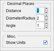
Label Settings popup
-
Decimal Places
The options in this sub group are used to set measurements to a specific decimal place by either clicking the up or down arrows to incrementally increase the places or else the number of places can be manually edited and typed into the number field. The following options are available to have their decimal places set: Distance, Diameter/Radius, and Angle. -
Misc.
Show Units — toggle this option on (check) to display the units being used.
Angles sub group
 Inside Angle — selecting this option means that the angle will be measure from the shortest distance between the two points selected (usually 90 degrees or less).
![]() Outside Angle — selecting this option means that the angle will be measure from the longest distance between the two points selected (usually over 90 degrees).
Outside Angle — selecting this option means that the angle will be measure from the longest distance between the two points selected (usually over 90 degrees).

![]() Supplement Angle — selecting this option will flip the measured angle by 180 degrees.
Supplement Angle — selecting this option will flip the measured angle by 180 degrees.
Circle sub group
 Radius — select this option to measure from the center of the circle to the end of the circle.
![]() Diameter — select this option to measure from one end of the circle to its opposite end.
Diameter — select this option to measure from one end of the circle to its opposite end.
 Center — select this option to find the mid point of the circle.
 Set Datum Reference — Select this option when creating Inspection images in the Annotated Images window to define any surface as a datum.
![]() Add Surface Finish — Select this option to alter the surface finish of your stock.
Add Surface Finish — Select this option to alter the surface finish of your stock.