Vericut X-Caliper Features
The following X-Caliper features are only available when using a reviewer file created in Vericut Simulation. If a feature is not listed here, it is shared between the X-Caliper tab of all software and will be explained on the Common Features page.
Feature/History
Location: X-Caliper tab >  (Feature/History)
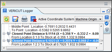
The Feature/History command button is used to obtain related cut feature (mathematical description) and NC program history. The historical data includes: NC program file name, record number, and NC program record text responsible for cutting the feature. This function is useful to spot-check machined features, and determine the source of an error cut identified in red by Vericut.
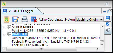
Sample Vericut Logger panel, X-Caliper tab results:
The following are geometric features identified by Vericut, listed alphabetically:
AUTO-DIFF model — (X, Y, Z value and surface normal) an uncut surface on a model displayed after an auto-difference Solid method comparison.
Circle — (X, Y, Z center, axis vector and radius) a surface cut by a circular motion.
Cone — (X, Y, Z center, axis vector and side angle) a hole bottom cut by an angle tip drill, corner cut by a tapered end mill, or chamfer cut by a turning operation.
Cylinder — (X, Y, Z center, axis vector and radius) an inside corner cut by 2 linear motions having an interior angle less than 180 degree, fillet cut by a bull or ball end mill moving perpendicular to the tool axis, or diameter cut by a turning operation.
Ellipse — (X, Y, Z center, axis vector, major and minor focal distances) a ramping or plunging surface cut by the bottom of an end mill with a flat, or partially flat, bottom.
Elliptical Solid of Revolution — (X, Y, Z center, axis vector, tool, and NC program record) generated on the outward portion of a canted circle sweep.
Fixture model — (X, Y, Z value and surface normal) generated on an uncut surface on a fixture model.
Helical Surface — (X, Y, Z center, axis vector, major radius, length of travel, number of rotations, NC program file, line number and NC program record, feed rate, and tool) a surface cut by a helical motion.
Holder Collision Area — (X, Y, Z value and surface normal) a holder/stock collision area cut stock model. Data also includes NC program file, record number and tool ID.
Plane — (X,Y,Z value and surface normal) a flat machined surface. Cylinders or circles cut using linear motions can also return this identity.
Ruled surface — (X,Y,Z value and surface normal) a surface cut by a multi-axis motion.
Sphere — (X, Y, Z center and radius) a surface cut by the end of a ball end mill.
Stock model — (X, Y, Z value and surface normal) an uncut surface on a stock model.
Torus — (X, Y, Z center, axis vector, major and minor radius) a fillet in a corner cut by a bull end mill, or fillet left on a diameter by the radius of the cutter during a turning operation.
Torus sweep — (X, Y, Z center, axis vector and major radius) This feature is typical of an angled (ramping or plunging) surface cut by a bull end mill.
When Feature/History is selected, the Settings group changes to the following:
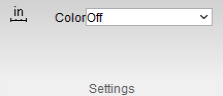
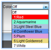
Color — The Color option enables you to view the entire cut that created the selected feature. To activate the Color option, select one of the colors from the pull-down list. When you select a feature in the graphics area, Vericut highlights the "history" (aka the cut) that created the feature with the selected color. To turn off the Color option, select "Off" from the pull-down list.
Closest Point
Location: X-Caliper tab > (Closest Point)
The Closest Point command button is used to measure the shortest distance from an XYZ point location to the closest point on the model surface.
Sample Vericut Logger panel, X-Caliper tab results:
Location — Represents the XYZ coordinates of the point to measure from. XYZ values must be manually entered in the Location text filed. The Closest Point, "From" Location cannot be specified by selecting the location graphically.
Measurement results are displayed in the Vericut Logger panel. Data output includes the From Location, the XYZ coordinates of the closest point on the model, and the measured distance between the "from" point and the "closest" point on the model.
When Closest Point is selected, the Settings group changes to the following:
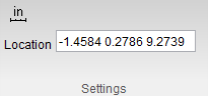
The Location text field can be manually edited.
Volume
Location: X-Caliper tab >  (Volume)
The Volume command button calculates and displays the following volume values for a selected stock workpiece: current cut stock volume, original stock model volume, and volume of material removed from the original stock model. All volumes are in cubic units.
In addition to the total volume of the selected model, if model consists of several disjoint pieces, the volume of a selected contiguous piece of material can also be analyzed. In this case, a bounding box is drawn around the selected piece to indicate what is being calculated. If the model is only one piece, no bounding box is drawn.
Sample Vericut Logger panel, X-Caliper tab results:
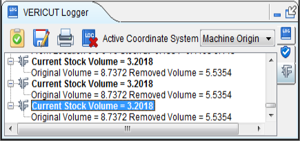
Calculated volumes are displayed in the X-Caliper window. Data output includes the Current Stock Volume, Original Volume, and Removed Volume.
When Volume is selected, the Settings group changes to the following:

Stock/Design Distance
Location: X-Caliper tab > Stock/Design Distance group
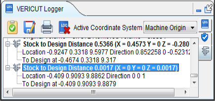
The Stock/Design Distance command buttons enable you to measure the distance between the cut stock and the design model.
Sample Vericut Logger panel, X-Caliper tab results:
Stock — Use to specify how you want to display the stock model(s) in the Workpiece and/or Profile views. Options are provided to enable you to display the model(s) as Solid,Translucent / Lines, or to turn the display Off.
Design — Similar to Stock, above, except that it applies to design model(s).
From Stock to Design / From Design to Stock — Use to specify the "From" and "To" components for the measurement.
Location — Represents the XYZ coordinates of the point to measure from on the "From" component.
Direction — Represents IJK of the measurement direction vector toward the "To" component.
Pick a location on the "From" component in the Workpiece or Profile view. X-caliper then measures the distance, normal to the pick location, to the nearest point on the "To" component. You can also enter the X, Y, and Z coordinates in the Location data field, separated by blank spaces, of the desired measurement point on the "From" component.
Data from the screen pick fills the Location and Direction data fields. If needed, you can edit the data in these fields, and then press Measure to obtain a measurement.
Measurement results are displayed in the X-Caliper window. Data output includes the measurement method, Location and Direction values related to the "From" component, the XYZ point of contact on the "To" component, and the measured Distance between the Location and the point of contact on the "To" component.
When Stock/Design is selected, the Settings group changes to the following:
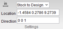
Location and Direction text fields can be edited manually.
Center of Gravity
Location: X-Caliper tab >  (Center of Gravity)
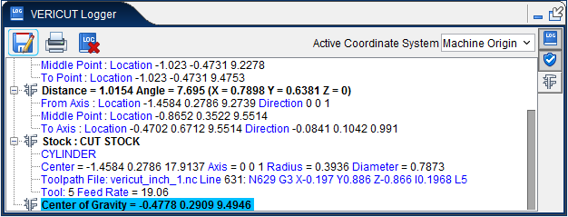
Reports X Y Z values of the calculated center of gravity point for the current cut stock model. If multiple cut stock models exist, user is prompted to select one. Information is also displayed in the Logger as shown below:
Highlight Same Plane
Location: X-Caliper tab >  (Highlight Same Plane)
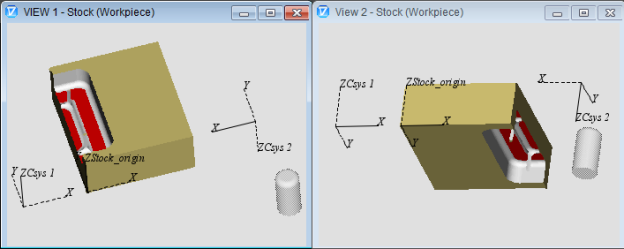
The Highlight Same Plane/Cylinder command button enables you to select a plane and have Vericut highlight all "cut" features that lie in the same plane. Only planes that have the same orientation (direction of the plane’s surface normal vector) and the same Z height, within the specified tolerance, will be displayed.
It also enables you to select a cylinder and Vericut will highlight all cylinders that have the same radius, within the specified tolerance value, regardless of the cylinder’s orientation (cylinder’s axis vector).
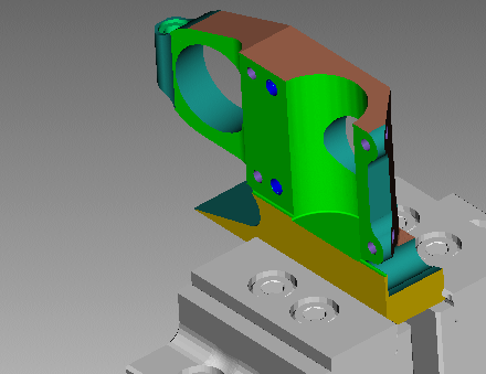
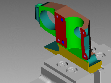
Select Highlight Same Plane/Cylinder and then select any plane or cylinder on the stock workpiece in the Workpiece view window. The plane or cylinder and any related plane or cylinder will become highlighted in the color of your choice (specified in the X-Caliper Settings group).
| Before selection: | After selection: |
|---|---|
 |
 |
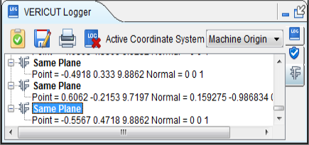
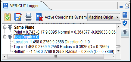
Sample Vericut Logger panel, X-Caliper tab results:
📝 NOTE: Highlight Same Plane/Cylinder can only be used in a Workpiece view.
When Highlight Same Plane is selected, the Settings group changes to the following:
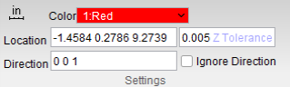
Color — Use to select the color to highlight the planes. Select the desired color from the pull-down color list.
Location — Represents the XYZ coordinates of the screen pick.
Direction — Represents IJK of the plane's normal vector at the location of the screen pick.
Data from the screen pick fills the Location and Direction data fields.
Z Tolerance — Use to specify a tolerance value for determining "same" planes. All planes, within ± the tolerance value, along the normal vector will be highlighted using the specified color.
Ignore Direction — When toggled on (checked), Vericut will find all “same” planes regardless of the plane’s orientation (direction of the plane’s surface normal vector). See the example below.
Result with Ignore Direction toggled off.
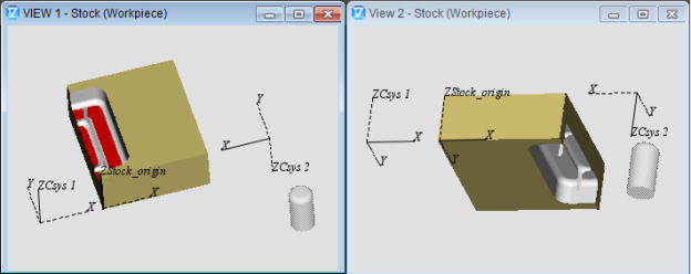
Result with Ignore Direction toggled on.
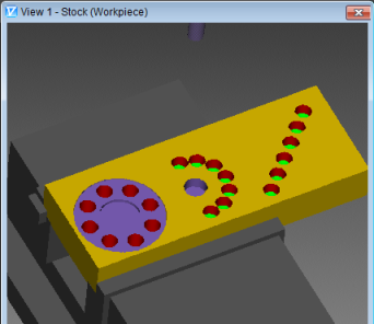
Sample Graphics display after using the Highlight Same Plane/Cylinder option on a plane:
Sample Graphics display after using the Highlight Same Plane/Cylinder option on a cylinder:
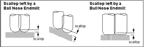
Scallop
Location: X-Caliper tab > Scallop group
The Scallop command buttons are used to measure the height of a scallop formed by two parallel intersecting cylinders. Select the two parallel and intersecting cylinders on the Vericut model that form the scallop. X-Caliper identifies the cylinders being measured by displaying intersecting circles on the model.
Sample Vericut Logger panel, X-Caliper tab results:

📝 NOTE: Machined features can only be measured in a workpiece view.
Cylinder 1 / Cylinder 2 — Used to define the cylinders to measure from and to. Use the choice arrow ![]() to control which cylinder is being picked. Select parallel cylinders on the Vericut model. After selecting Cylinder 1, Vericut displays a circle representing the cylinder in the graphics area and automatically transfers control to Cylinder 2. After selecting Cylinder 2, measurement results are displayed in the X-Caliper window.
to control which cylinder is being picked. Select parallel cylinders on the Vericut model. After selecting Cylinder 1, Vericut displays a circle representing the cylinder in the graphics area and automatically transfers control to Cylinder 2. After selecting Cylinder 2, measurement results are displayed in the X-Caliper window.
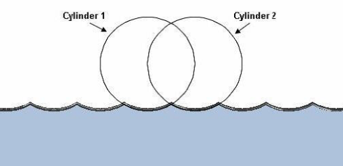
Data output includes Center point, Axis vector, and Radius values for each cylinder and the Scallop Height measurement.
Hole Depth
Location: X-Caliper tab > Hole Depth group
The Hole Depth command buttons enable you to measure the depth of a hole or of a chamfer.
Sample Vericut Logger panel, X-Caliper tab results:
Hole Top — This is the feature that defines the top of the hole (generally a plane).
Location — Represents the XYZ coordinates of the screen pick.
Vericut uses data from the screen pick to fill in the "feature type" and the Location data field.
Hole Bottom — This is the feature that defines the bottom of the hole.
Location — Represents the XYZ coordinates of the screen pick.
Vericut uses data from the screen pick to fill in the "feature type" and the Location data field.
Feature — Use to specify the feature that you want to measure.
When Hole Depth command buttons are selected, the Settings group changes to the following:
Location text field can be edited manually.
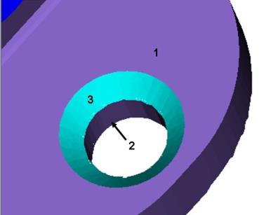
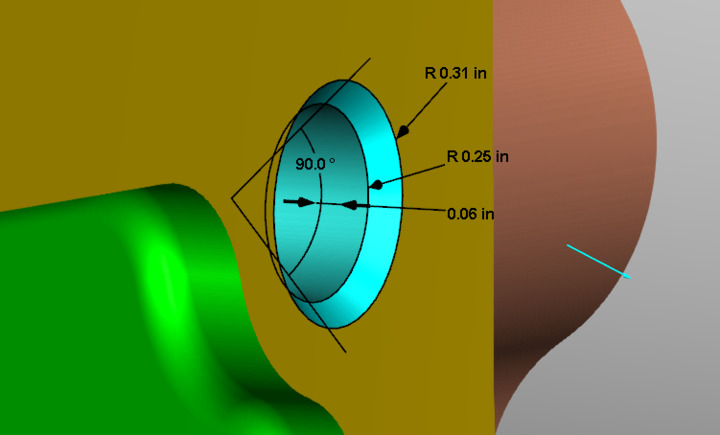
Using Hole Depth
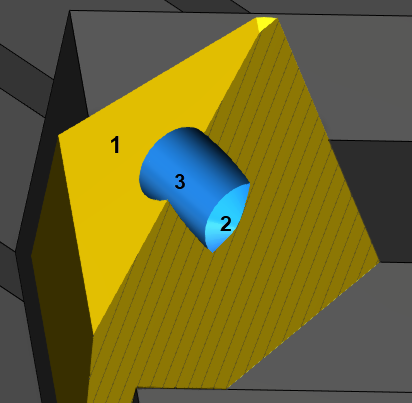
Refer to the picture of the hole cross section above for the following example.
To measure the depth of the hole:
-
In the X-Caliper tab, click on
 (Hole Top), and then pick the feature representing the top of the hole. In this case it is a plane represented by 1 in the picture.
 -
In the X-Caliper tab, click on
 (Hole Bottom), and then pick the feature representing the bottom of the hole. In this case it is a cone represented by 2 in the picture.
 - In the X-Caliper tab, click on
 (Feature), and then pick the feature that you want to measure. In this case it is a cylinder represented by 3 in the picture.
X-Caliper will calculate the depth from the intersection of the plane and the cylinder to the intersection of the cone and the cylinder.
Refer to the picture above for the following example.
To measure the depth of the top chamfer/countersink:
-
In the X-Caliper tab, click on
(Hole Top), and then pick the feature representing the top of the chamfer. In this case it is a plane represented by 1 in the picture. -
In the X-Caliper tab, click on
(Hole Bottom), and then pick the feature representing the bottom of the chamfer. In this case it is a cylinder represented by 2 in the picture. -
In the X-Caliper tab, click on
 (Feature), and then pick the feature that you want to measure. In this case it is a cone represented by 3 in the picture. X-Caliper will calculate the depth from the intersection of the plane and the cone to the intersection of the cone and the cylinder.
 -
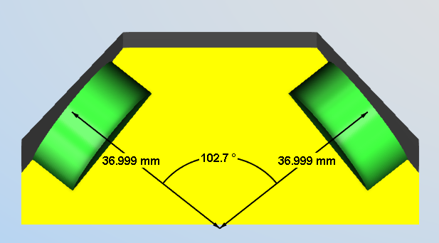
To determine the angle of a chamfer/countersink, open the Vericut Logger, X-Caliper tab.
- In the Feature/History window, pick the cone represented by 3 in the picture.
C-Sink Depth
The command buttons in the Hole Depth group enable you to measure the tops and bottoms of features as well as the C-Sink depth.
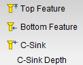
 Top Feature — This is used to define the top of a C-Sink.
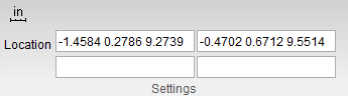
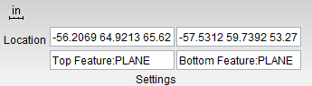
Location — Represents the XYZ coordinates of the screen pick.
Vericut uses data from the screen pick to fill in the "feature type" and the Location data field in the X-Caliper Settings group as shown in the picture below. After the Top Feature has been selected, Bottom Feature becomes active.
 Bottom Feature — This is used to define the bottom of a C-Sink.
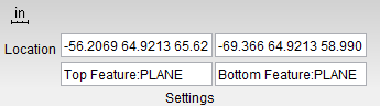
 C-Sink — This is used to measure the depth of a feature. It is similar to Hole Depth but measures only as far down as the specified Bottom Feature rather than measuring the entire depth of the hole. Once all of these have been set, you will see your measured c-sink appear as in the following example:
Axis Intersection
The command buttons in the Axis Intersection group enable you to measure the point in which two axes intersect and the distance from this point to an intersecting plane along those axes.
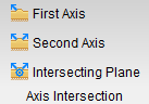
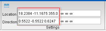
First Axis — This is used to define one axis of the intersection.
Vericut uses data from the screen pick to fill in the Direction and Location data fields in the X-Caliper Settings group as shown in the picture below. After the First Axis has been selected, the Second Axis becomes active.
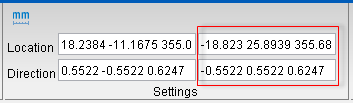
Second Axis — This is used to define the other axis of the intersection.
Vericut will issue a warning if this axis does not intersect with the first and prompt for reselection. After Second Axis has been selected, the axis intersection with the angle is displayed in the View Window and Bottom Feature becomes active.
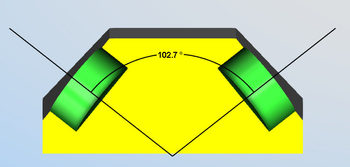
Intersecting Plane — This is used to define a plane that intersects one or both axes to measure the distance from the axis-axis intersection point to the axis-plane intersection point along the axis.
Vericut will issue a warning if this plane does not intersect with at least one of the axes and prompt for reselection.
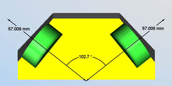
📝 NOTE: Each distance and angle measurement are individually selectable so that those deemed unnecessary can be removed from view. This can be combined to show distances from the same axis intersection to multiple planes.