Using the Tool Manager
About Describing Tools for Vericut
Vericut requires descriptions of the tools used to machine the workpiece to accurately simulate the material removal process. Vericut can process all standard APT CUTTER records to obtain descriptions of cutting tools (as well as relevant records for non-cutting tools), or you can define cutting tools via Vericut's Tool Manager and store them in a Tool Library file. When non-cutting tool holders are defined and used in the simulation, Vericut detects collisions that would occur with tool holder(s) and the workpiece or holding fixtures. A summary of the tools used during the simulation and machine cycle time elapsed for each tool is written to the Log file.
If Vericut does not have a description of the tool when NC program processing begins, the previous tool is used. If a previous tool has not been defined, an error similar to "Tool not defined - motion ignored" is issued.
Vericut supports a variety of tools, depending on the type of machining they will perform:
Milling Tools
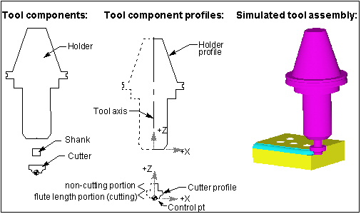
A milling tool assembly consists of these components:
Holder — The Holder component grips the cutter and holds it in the NC machine for cutting and is described using the Tool Component tab (Holder) features in Tool Manager.
The holder component is also used for collision detection. Vericut enables using multiple holder components. Other non-cutting components found in milling tool assemblies, such as: chucks, extensions, adapters, etc. are described using "Holder" components in Vericut.
Cutter — Cutting portion of the tool assembly-has flutes, or teeth, that remove material and is described using the Tool Component tab (Revolved Cutter) features in Tool Manager. The cutting portion of the tool assembly can also be described as one or more cutter inserts using the Tool Component tab (Mill Insert) features or the features in the Mill Tool with Cutter Body window in Tool Manager.
Shank — the portion of the tool assembly that extends above the cutter, and into the holder. It does not have flutes and cannot effectively remove material. Vericut offers the following methods of defining a non-cutting shank:
Cutter + Flute Length method — using the Tool Manager, define a Cutter which includes the shank portion of the tool, then specify its cutting Flute Length and Shank Diameter.
Holder method — in addition to defining the Cutter, you also define a separate Holder (see below) which describes the shank portion of the tool. Flute Length is not used with this method.
Shank method — in addition to defining the Cutter, use special Cutter or Vericut-TC records to describe the shank profile. Flute Length is not used with this method.
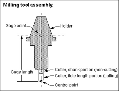
Milling tool control point
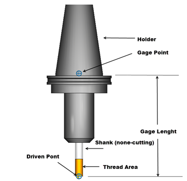
The tool control point, or "driven point" is a point relative to the tool assembly that the NC data is commanding to move. Material is removed based on motion commands and the tool shape, relative to the control point. By default, Vericut assumes the mill tool tip (bottom center of the tool) is being driven. However, this relationship can be changed by including a Driven Point record for the tool in the Tool Manager window, Tool Information tab.
In cases where a gage point is driven, such as with G-Code data for a machine expecting to drive the spindle face or rotary pivot point, a gage length or "gage offset" value is often used. A gage offset value establishes the expected length for the tool to be extended from the holder. Vericut realistically simulates this programming method by allowing you to enter these values in a Gage Offset table or by including a Gage Point location for the tool in the Tool Manager window, Tool Information tab.
Turning Tools
A turning tool assembly consists of these components:
Holder — The Holder component grips the Cutter and holds it in the NC machine for cutting and is described using the Tool Component tab (Holder) features in Tool Manager.
The holder component is also used for collision detection. Vericut enables using multiple holder components. Other non-cutting components found in Turning tool assemblies, such as: backup blocks, extensions, adapters, etc. are described using "Holder" components in Vericut.
Cutter — Cutting portion of the tool, sometimes referred to as a turning "insert" is used to remove material and is described using the Tool Component tab (Turn Insert) features in Tool Manager.
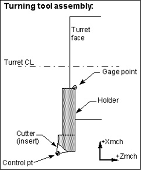
Turning tool control point
The tool control point, or "driven point" is a point relative to the tool assembly that the NC data is commanding to move. Material is removed based on motion commands and the tool shape, relative to the control point. By default, Vericut assumes the center the turning tool tip is being driven. However, this relationship can be changed by including a Driven Point record for the tool in the Tool Manager window, Tool Information tab.
In cases where a gage point is driven, such as with G-Code data for a machine expecting to drive the turret face or center, gage offset values are often used. These values establish where the NC data control point is, relative to the actual machine driven point. Vericut realistically simulates this programming method by allowing you to enter these values in a Gage Offset table or by including a Gage Point location for the tool in the Tool Manager window, Tool Information tab.
Suggested Workflow for Importing Turning Tools
The following is an ideal approach to how to manager importing of turning tools.
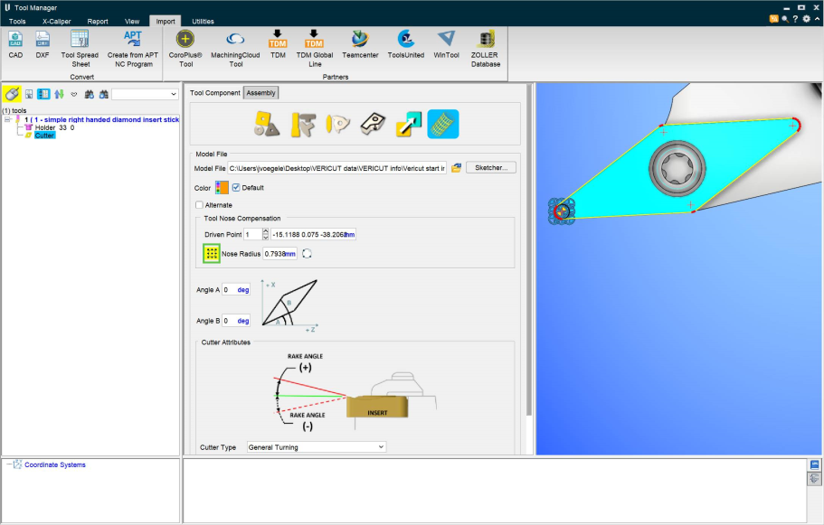
First, make sure a turning tool is being imported by setting the features correctly through Tool Manager > Import tab > Import CAD Tool. Below is a photo of what such settings may look like. Critical fields are highlighted with a green box.

Select the appropriate cutting face for each insert present on the tool assembly > Add New Tool. Then return to Tool Manager and select the insert.
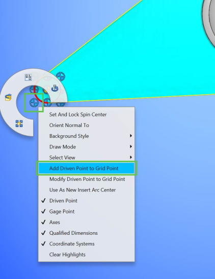
In the Tool Component tab, select the insert > ![]() click to Display Driven Point grid.
click to Display Driven Point grid.
📝 NOTE: The Cutting Face(s) will display with red radii and yellow line segments
📝 NOTE: The Nose Radius value is automatically detected
If 3x3 Driven Point grid is in correct location > hover mouse over the desired Driven Point location > RMB > Add Driven Point to Grid Point.
If 3x3 Driven Point grid is not in correct location, does a red radius exist on the insert corner of desired Driven Point location?
If YES (red radius exists on a desired insert corner) > hover mouse over the desired insert corner > RMB > Use As New Insert Arc Center. This will move the 3x3 Driven Point grid to the desired location. Then make the desired Driven Point selection as described above.

If NO (red radius does NOT exists on a desired insert corner) >
Unclick ![]() to not Display Driven Point grid
to not Display Driven Point grid
Click ![]() to Define Nose Radius Circle
to Define Nose Radius Circle
Window any 3 points from a Cutting Face to define a Nose Radius location

This should display 3x3 Driven Point grid with a black line Nose Radius in correct insert corner (If not, reselect)
Then make the desired Driven Point selection as described above.
This process can be repeated if additional Driven Point locations need to be defined (I.e. the opposite corner of a groove insert)
📝 NOTE: As Driven Point(s) are defined using the above workflow, a Qualified Dimension is automatically defined.
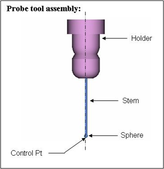
Probe Tools
A Probe tool assembly consists of these components:
Holder — The Holder grips the probe tip and holds it in the NC machine for probing and is described using the Tool Component tab (Holder) features in Tool Manager. The holder component is also used for collision detection.
Other non-cutting components found in Probe tool assemblies, are described using "Holder" components in Vericut.
Probe Ball — The probe consists of a "tip" of specified shape (Ball, Cylinder, Hemisphere, Disk and Extension), a shank/stem with a specified diameter, and an overall length. It is described using the Tool Component tab (Probe Tip) features in Tool Manager.
A probe tool does not cut. In fact, Vericut's material removal logic is never used for a probe tool. This is mainly because a probe tool, unlike a milling tool, does not have to be symmetric about an axis of rotation. Thus Vericut can support multiple tip probe tool configurations like a "star" probes. This design also positions us to be able to support asymmetric probe tips in some future release.
Vericut's collision logic for a probe tool is more like that of a turning tool. As with a turning tool, a probe tool uses machine simulation's collision algorithm to detect collisions. No material is removed, but errors are reported in the logger and log file, and the error counter is incremented. If a machine simulation view is open and simulation and collision checking is on, you will see the usual error color display.
Hole Making Tools
A Hole Making tool assembly consists of these components:
Holder — The Holder component grips the Cutter and holds it in the NC machine for cutting and is described using the Tool Component tab (Holder) features in Tool Manager.
The holder component is also used for collision detection. Vericut enables using multiple holder components. Other non-cutting components found in Hole Making tool assemblies, such as: extensions, adapters, etc. are described using "Holder" components in Vericut.
Cutter — The Cutter component of the tool assembly (Drills, Reamers, Center Drills and Taps) is used to remove material and is described using the Tool Component tab (Hole Making Tool) features in Tool Manager.
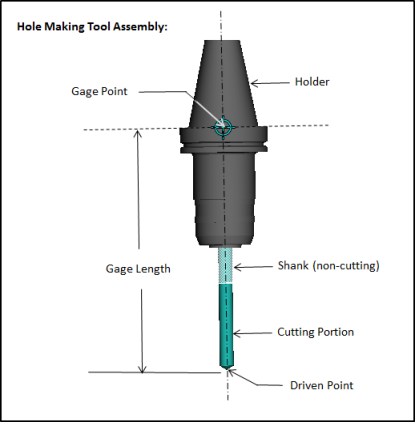
Hole Making Tool control point
The tool control point, or "driven point" is a point relative to the tool assembly that the NC data is commanding to move. Material is removed based on motion commands and the tool shape, relative to the control point. By default, Vericut assumes the Hole Making tool tip (bottom center of the tool) is being driven. However, this relationship can be changed by including a Driven Point record for the tool in the Tool Manager window, Tool Information tab.
In cases where a gage point is driven, such as with G-Code data for a machine expecting to drive the spindle face or rotary pivot point, a gage length or "gage offset" value is often used. A gage offset value establishes the expected length for the tool to be extended from the holder. Vericut realistically simulates this programming method by allowing you to enter these values in a Gage Offset table or by including a Gage Point location for the tool in the Tool Manager window, Tool Information tab.
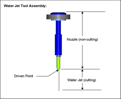
Water Jet Tools
A Water Jet tool assembly consists of these components:
Holder — The holder, or nozzle, grips the water jet cutter and holds it in the NC machine for water jet cutting and is described using the Tool Component tab, Holder features in Tool Manager.
The holder component is also used for collision detection. Vericut enables using multiple holder components. Other non-cutting components found in Water Jet tool assemblies, such as: mixing tubes, guards, etc. are described using tool "Holder" components in Vericut. The holder component is also used for collision detection.
Water Jet — The portion of the tool assembly that is used to form the water jet stream that is used is used to remove material and is described using the Tool Component tab (Water Jet) features in Tool Manager.
Water Jet tool control point
The tool control point, or "driven point" is a point relative to the tool assembly that the NC data is commanding to move. Material is removed based on motion commands and the water jet tool configuration, relative to the control point. By default, Vericut assumes the water jet tool tip (bottom center of the tool) is being driven. However, this relationship can be changed by including a Driven Point record for the tool in the Tool Manager window, Tool Information tab.
In cases where a gage point is driven, such as with G-Code data for a machine expecting to drive the spindle face or rotary pivot point, a gage length or "gage offset" value is often used. A gage offset value establishes the expected length for the tool to be extended from the holder. Vericut realistically simulates this programming method by allowing you to enter these values in a Gage Offset table or by including a Gage Point location for the tool in the Tool Manager window, Tool Information tab.
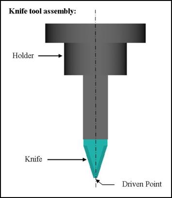
Knife Tools
A Knife tool assembly consists of these components:
Holder — The holder grips the knife cutter and holds it in the NC machine for ultrasonic knife cutting and is described using the Tool Component tab (Holder) features in Tool Manager.
The holder component is also used for collision detection. Vericut enables using multiple holder components. Other non-cutting components found in polisher tool assemblies, such as: extensions, adapters, etc. are described using tool "Holder" components in Vericut.
Knife — The Knife portion of the tool assembly that is used for cutting and is described using the Tool Component tab (Knife) features in Tool Manager.
Knife tool control point
The tool control point, or "driven point" is a point relative to the tool assembly that the NC data is commanding to move. Material is cut based on motion commands and the knife tool configuration, relative to the control point. By default, Vericut assumes the knife tool tip (bottom center of the tool) is being driven. However, this relationship can be changed by including a Driven Point record for the tool in the Tool Manager window, Tool Information tab.
In cases where a gage point is driven, such as with G-Code data for a machine expecting to drive the spindle face or rotary pivot point, a gage length or "gage offset" value is often used. A gage offset value establishes the expected length for the tool to be extended from the holder. Vericut realistically simulates this programming method by allowing you to enter these values in a Gage Offset table or by including a Gage Offset location for the tool in the Tool Manager window, Tool Information tab.
Polisher Tools
A Polisher tool assembly consists of these components:
Holder — The holder, or nozzle, grips the Polisher tool and holds it in the NC machine for polishing and deburring and is described using the Tool Component tab (Holder) features in Tool Manager.
The holder component is also used for collision detection. Vericut enables using multiple holder components. Other non-cutting components found in polisher tool assemblies, such as: extensions, adapters, etc. are described using tool "Holder" components in Vericut.
Polisher — The "outer" portion of the Polisher tool assembly that is used to polish or Deburr the part and is described using the Tool Component tab (Polisher) features in Tool Manager. The Polisher component is described using the Add Tool Component feature in the Tool Manager.
Polisher Limits — The "inner" portion of the Polisher tool assembly that is used to detect areas where the tool applied too much pressure on the part (penetrates the part too deep). A negative near-miss value could be used instead of a Polish Limits component but using a Polish Limits component might be preferable because the allowable deflection can vary with the tool contact point. The Polish Limits component is described using the Tool Component tab (Polisher) features in Tool Manager.
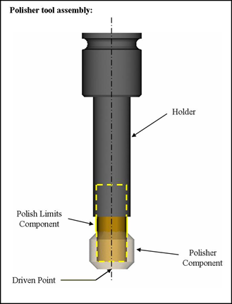
Polisher tool control point
The tool control point, or "driven point" is a point relative to the tool assembly that the NC data is commanding to move. Material is polished based on motion commands and the polisher tool configuration, relative to the control point. By default, Vericut assumes the polisher tool tip (bottom center of the tool) is being driven. However, this relationship can be changed by including a Driven Point record for the tool in the Tool Manager window, Tool Information tab.
In cases where a gage point is driven, such as with G-Code data for a machine expecting to drive the spindle face or rotary pivot point, a gage length or "gage offset" value is often used. A gage offset value establishes the expected length for the tool to be extended from the holder. Vericut realistically simulates this programming method by allowing you to enter these values in a Gage Offset table or by including a Gage Offset location for the tool in the Tool Manager window, Tool Information tab.
Additive Tools
An Additive tool consists of the following components:
Holder — The holder, or nozzle, grips the Polisher tool and holds it in the NC machine for polishing and deburring and is described using the Tool Component tab (Holder) features in Tool Manager.
The holder component is also used for collision detection. Vericut enables using multiple holder components. Other non-cutting components found in polisher tool assemblies, such as: extensions, adapters, etc. are described using tool "Holder" components in Vericut.
Bead — The Additive tool consists of a high powered laser that melts selected sections of the machined product and a metal-based spray that is sprayed onto the melted layer binding this new layer onto the existing product causing beads of new material to form. The Additive tool itself does not change but the laser it emits and the size of the additive beads it creates. The bead component is defined using the Add Tool Component feature in the Tool Manager.
Grinder Tools
A grinder tool consists of these components:
Holder — The holder that grips the Grinding wheel cutter and holds it in the NC machine for Grinding the part and is described using the Tool Component tab (Holder) features in Tool Manager.
The holder component is also used for collision detection. Vericut enables using multiple holder components. Other non-cutting components found in Grinding tool assemblies, such as: extensions, adapters, etc. are described using tool "Holder" components in Vericut.
Grinder — The grinder tool is composed of an abrasive surface wheel that is described in the Tool Component tab (Grinder). The grinder component is defined using the Add Tool Component feature in the Tool Manager.
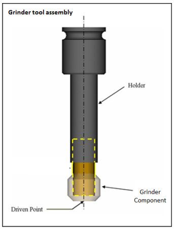
Grinder tool control point
The tool control point, or "driven point" is a point relative to the tool assembly that the NC data is commanding to move. Material is cut based on motion commands and the knife tool configuration, relative to the control point. By default, Vericut assumes the grinder tool tip (bottom center of the tool) is being driven. However, this relationship can be changed by including a Driven Point record for the tool in the Tool Manager window, Tool Information tab.
In cases where a gage point is driven, such as with G-Code data for a machine expecting to drive the spindle face or rotary pivot point, a gage length or "gage offset" value is often used. A gage offset value establishes the expected length for the tool to be extended from the holder. Vericut realistically simulates this programming method by allowing you to enter these values in a Gage Offset table or by including a Gage Offset location for the tool in the Tool Manager window, Tool Information tab.
Dresser Tools
A dresser tool consists of these components:
Holder — The holder that grips the dresser cutter and holds it in the NC machine for Dressing the Grinding wheel unit and is described using the Tool Component tab (Holder) features in Tool Manager.
The holder component is also used for collision detection. Vericut enables using multiple holder components. Other non-cutting components found in Dressing tool assemblies, such as: extensions, adapters, etc. are described using tool "Holder" components in Vericut.
Dresser — The dresser tool is composed of grinding dresser used to alter the surface of a grinding wheel that is the Tool Component tab (Dresser). The dresser component is defined using the Add Tool Component feature in the Tool Manager.
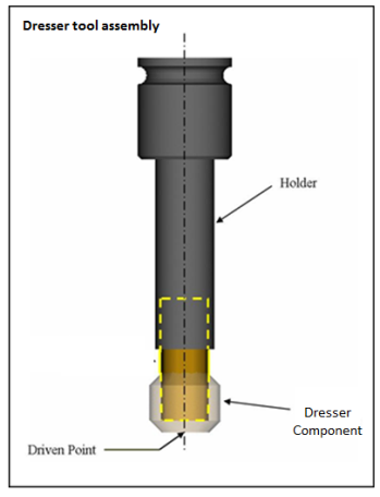
Dresser tool control point
The tool control point, or "driven point" is a point relative to the tool assembly that the NC data is commanding to move. Material is cut based on motion commands and the dresser tool configuration, relative to the control point. By default, Vericut assumes the knife tool tip (bottom center of the tool) is being driven. However, this relationship can be changed by including a Driven Point record for the tool in the Tool Manager window, Tool Information tab.
In cases where a gage point is driven, such as with G-Code data for a machine expecting to drive the spindle face or rotary pivot point, a gage length or "gage offset" value is often used. A gage offset value establishes the expected length for the tool to be extended from the holder. Vericut realistically simulates this programming method by allowing you to enter these values in a Gage Offset table or by including a Gage Offset location for the tool in the Tool Manager window, Tool Information tab.
Thread Mill Tools
A Thread Mill tool assembly consists of these components:
Holder — The Holder component grips the cutter and holds it in the NC machine for cutting and is described using the Tool Component tab (Holder) features in Tool Manager.
The holder component is also used for collision detection. Vericut enables using multiple holder components. Other non-cutting components found in milling tool assemblies, such as: chucks, extensions, adapters, etc. are described using "Holder" components in Vericut.
Cutter — Cutting portion of the tool assembly-has flutes, or teeth, that remove material and is described using the Tool Component tab (Thread Mill) features in Tool Manager. The cutting portion of the tool assembly. In the Mill Tool with Cutter Body window in Tool Manager.
Shank — the portion of the tool assembly that extends above the cutter, and into the holder. It does not have flutes and cannot effectively remove material. Vericut offers the following methods of defining a non-cutting shank:
Cutter + Flute Length method — using the Tool Manager, define a Cutter which includes the shank portion of the tool, then specify its cutting Flute Length and Shank Diameter.
Holder method — in addition to defining the Cutter, you also define a separate Holder (see below) which describes the shank portion of the tool. Flute Length is not used with this method.
Shank method — in addition to defining the Cutter, use special Cutter or Vericut-TC records to describe the shank profile. Flute Length is not used with this method.
Milling tool control point
The tool control point, or "driven point" is a point relative to the tool assembly that the NC data is commanding to move. Material is removed based on motion commands and the tool shape, relative to the control point. By default, Vericut assumes the mill tool tip (bottom center of the tool) is being driven. However, this relationship can be changed by including a Driven Point record for the tool in the Tool Manager window, Tool Information tab.
In cases where a gage point is driven, such as with G-Code data for a machine expecting to drive the spindle face or rotary pivot point, a gage length or "gage offset" value is often used. A gage offset value establishes the expected length for the tool to be extended from the holder. Vericut realistically simulates this programming method by allowing you to enter these values in a Gage Offset table or by including a Gage Offset location for the tool in the Tool Manager window, Tool Information tab.
Electrode Tools
An Electrode tool assembly consists of these components:
Holder — The Holder component grips the cutter and holds it in the NC machine for cutting and is described using the Tool Component tab (Holder) features in Tool Manager.
The holder component is also used for collision detection. Vericut enables using multiple holder components. Other non-cutting components found in electrode tool assemblies, such as: chucks, extensions, adapters, etc. are described using "Holder" components in Vericut.
Electrode — The electrode portion of the electrode tool is a simple parametric round element defined by radius and height.
Electrode tool control point
The tool control point, or "driven point" is a point relative to the tool assembly that the NC data is commanding to move. Material is cut based on motion commands and the knife tool configuration, relative to the control point. By default, Vericut assumes the grinder tool tip (bottom center of the tool) is being driven. However, this relationship can be changed by including a Driven Point record for the tool in the Tool Manager window, Tool Information tab.
In cases where a gage point is driven, such as with G-Code data for a machine expecting to drive the spindle face or rotary pivot point, a gage length or "gage offset" value is often used. A gage offset value establishes the expected length for the tool to be extended from the holder. Vericut realistically simulates this programming method by allowing you to enter these values in a Gage Offset table or by including a Gage Offset location for the tool in the Tool Manager window, Tool Information tab.
Multi Tool Stations
A Multi Tool Station is different from other tool types in that it is an assemblage of holders that will contain the multiple tools the station has access to. Multi tool stations consist of these components:
Holder — The Holder component grips any tool that will be attached to the multi tool station and is described using the Tool Component tab (Holder) features in Tool Manager. Multiple holders can be added to a multi tool station.
Static/Live setting — This feature is used to designate whether to tools the multi tool station holds are static (non-rotating) or live (the tools rotate and need to have a set Z axis).
Multi tool stations do not have control points.
Defining Profile Tool Shapes
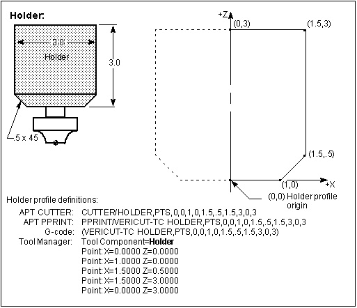
Using profile tool shapes, also known as "special cutters", extends the ability to describe tool shapes to include cutters having almost any cutting shape and differentiate the non-cutting portions of the tool assembly, such as: shanks, extensions and holders. Material is not removed by the non-cutting portion of a tool assembly but is immediately flagged as an error, and shaded using the red Error color.
CUTTER record profile tool definition formats:
CUTTER/XCUT, ...profile description
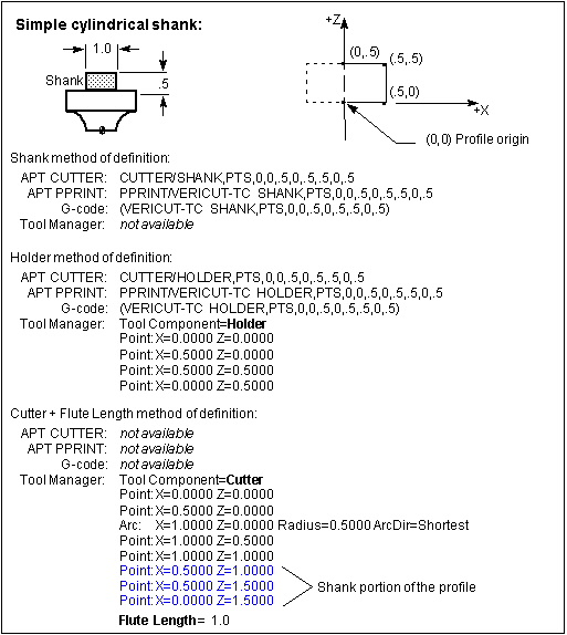
CUTTER/SHANK, ...profile description
CUTTER/HOLDER, ...profile description
APT/CLS version of Vericut-TC record profile tool definition formats:
PPRINT/Vericut-TC XCUT, ...profile description
PPRINT/Vericut-TC SHANK, ...profile description
PPRINT/Vericut-TC HOLDER, ...profile description
G-Code version of Vericut-TC record profile tool definition formats (Fanuc control example):
(Vericut-TC XCUT, ...profile description)
(Vericut-TC SHANK, ...profile description)
(Vericut-TC HOLDER, ...profile description)
Special cutter profiles are defined differently, depending on the tool type. Consult the following sections for specific information.
Milling tool profiles
Milling tool profiles are defined using a 2-D profile composed of line and arc segments in the ZX plane, which are then revolved by Vericut to create the spinning tool shape. The profile of each tool component (cutter or holder) is described in its own local coordinate system where the Z-axis is the tool centerline.
Vericut can also be configured to use profile holders with standard cutters that appear in the NC program file.
Vericut assumes the origin of the cutter component is being driven. However, this relationship can be changed by including a Driven Point record for the tool in the Tool Manager window, Tool Information tab.
In cases where a gage point is driven, such as with G-Code data for a machine expecting to drive the spindle face or rotary pivot point, a gage length or "gage offset" value is often used. A gage offset value establishes the expected length for the tool to be extended from the holder. Vericut realistically simulates this programming method by allowing you to enter these values in a Gage Offset table or by including a Gage Offset location for the tool in the Tool Manager window, Tool Information tab.
Sample milling tool assembly with profiles:
Milling tool profile entities
The entities used to define milling tool profiles are listed below. The profile for each tool component is defined relative to its own local coordinate system.
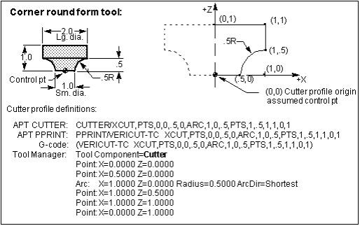
Point X,Z — Defines a point on the profile. When a point follows a previous point, a line segment is created connecting the points. When a point follows an arc, the point is used to limit the arc.
Points X,Z, X,Z, ... X,Z — Used only with special tool path record formats, this entity defines a series of points on the profile, each connected with a line segment.
Arc Xcenter, Zcenter, Radius [CW, CCW, Shortest] — Defines an arc segment. Control the Arc direction using the "CW", "CCW", or "Shortest" options. An Arc must be limited by a preceding and trailing point. Tool profiles cannot begin with, end with, or have two successive Arc entities.
Rules for defining milling tool profiles
-
The profile definition must begin with a Point at X=0, and may begin anywhere on the Z-axis (tool axis). Recall that the origin (X0Z0) of a cutter profile is assumed by Vericut as the control point.
-
The profile must have at least three points.
- In general, the profile definition is continues in a counter-clockwise direction, and ends with a point that is higher in Z than the beginning point. Vericut automatically closes any profile that does not end on the Z-axis by supplying an ending point at X=0 and perpendicular to the tool axis.
- The only profile restriction is that it cannot be self-intersecting (cross over on itself).
Vericut checks for valid profiles when:
-
The tls file is opened, either directly in tool manger or when the .usr file is opened.
-
You are creating the profile in the sketcher.
- If Vericut detects an invalid profile when the .tls file is opened or while you are creating it in the sketcher, Vericut will attempt to fix a bad profile if possible but sometimes it is not possible.
- Vericut is cutting.
- If Vericut detects an invalid cutter profile while cutting, a message is output, the error count is incremented, and the tool is not used. If it detects an invalid holder profile, a message is output, the error count in incremented, and the holder is turned-off.
Examples of defining a milling cutter profile:
Examples of defining a shank profile:
Examples of defining a holder profile:
Examples of "Negative Z" profiles:
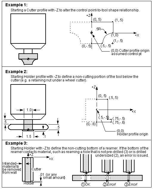
Example of a cutter profile with a "Negative Z" turn:
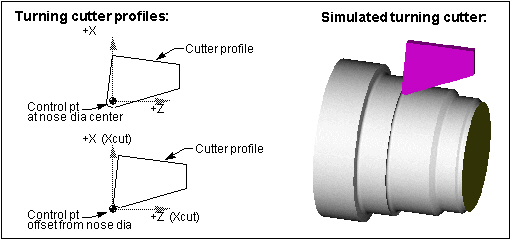
Turning tool profiles
Turning tool profiles are used to describe both the cutter (insert) tool component and holder components. Turning cutter components are defined using a "closed" 2-D profile composed of line and arc segments in the ZX plane and used to create a "sweep" solid of the specified Thickness by sweeping the profile along the Y-axis. The profile is described in a local coordinate system where the origin of the cutter component is assumed as the tool control point.
Turning holder components can be described as either a closed 2-D "sweep" profile composed of line and arc segments in the ZX plane and used to create a "sweep" solid of the specified Thickness, the same as the cutter component described above. Turning holder components can also be described as an "open" 2-D SOR (solid of revolution) profile, composed of line and arc segments in the ZX plane used to create a solid by revolving the profile around the Z-axis.
Vericut assumes the origin of the cutter component is being driven. However, this relationship can be changed by including a control point offset ("Ctrl Pt") with the tool in the Tool Manager.
Sample turning tool profile:
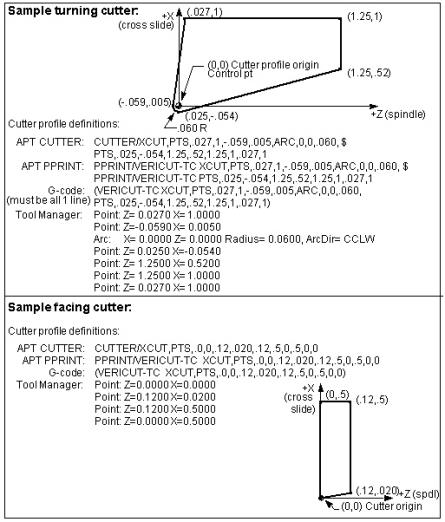
Turning tool profile entities
The data elements used to define turning tool profiles are listed below. The profile is defined relative to its local coordinate system. Note that Z=spindle axis and X=cross-slide axis.
Point Z,X — Defines a point on the profile. When a point follows a previous point, a line segment is created connecting the points. When a point follows an arc, the point is used to limit the arc.
Points Z,X, Z,X, ... Z,X — Used only with special tool path record formats, this entity defines a series of points on the profile, each connected with a line segment.
Arc Zcenter, Xcenter, Radius [CW, CCW, Shortest] — Defines an arc segment. Control the Arc direction using the "CW", "CCW", or "Shortest" options. An Arc must be limited by a preceding and trailing point. Tool profiles cannot begin with, end with, or have two successive Arc entities.
Rules for defining turning tool profiles
-
The profile definition must begin with a Point, and may begin anywhere in X and Z. Recall that the origin (X0Z0) of a cutter profile is assumed by Vericut as the control point.
-
The profile must have at least three points.
- In general, the profile definition is continues in a counter-clockwise direction, and ends with a point at the same location as the beginning point (creates a closed profile shape). Vericut automatically closes any profile that does not end on the beginning point by supplying an ending point at that location.
- The only profile restriction is that it cannot be self-intersecting (cross over on itself).
Examples of defining turning cutter profiles:
Accessing the Tool Manager
The Tool Manager enables you to create and maintain Vericut Tool Library files containing descriptions of cutting tools, or tool assemblies, Stock Material records and other tool related information used by Vericut. Vericut provides a variety of ways to access the Tool Manager enabling you to choose the method that works best for you. Choose from the following methods:
Accessing Tool Manager from the Project Tree:
-
Double-click with the left mouse button on a Tooling branch.
-
Right-click on a Tooling branch and select Tool Manager from the menu that displays.
Accessing Tool Manager from the Vericut main menu:
- In the Vericut main menu select Project tab > Tools.
Accessing Tool Manager from the Vericut toolbar:
- Click on
 , the Tools icon.
Accessing Tool Manager outside of Vericut:
You can access a stand-alone Tool Manager outside of Vericut using the toolman.bat file located in the \commands folder of your Vericut installation.
Create a New Tool Library File
Tool Library files contain descriptions of cutting tools, or tool assemblies. Tool Library data is used by Vericut when a setup’s Tooling Branch in the Project Tree is configured to do so. Use the procedure below to create a new Tool Library.
To create a new (blank) Tool Library file:
-
Open the Tool Manager window using one of the methods described above in the Accessing the Tool Manager section.
-
Click on the
 (New File) icon in the Tool Manager Tool Bar. All data is cleared from the Tool Manager.
 - Use the Tool Manager Add group features to add new tools or the
 (Add Component pull-down menu) features to add new tool components. Both are located in the Tool Manager Tool Bar.
 - See Adding a Tool to a Tool Library section of Tool Manager Standalone Help for more information.
- To save the new Tool Library file, click on the
 (Save File) in the Tool Manager Tool Bar then selected Save or Save As.
In the file selection window that opens, select or type the /path/filename for the new tool library file and then click Save.
Open an Existing Tool Library File
Tool Library files contain descriptions of cutting tools, or tool assemblies. Tool Library data is used by Vericut when a setup’s Tooling Branch in the Project Tree is configured to do so. Use the procedures below to open an existing Tool Library file.
To open an existing Tool Library file:
-
Open the Tool Manager window using one of the methods described in the Accessing the Tool Manager section.
-
Click on the
 command button in the Tool Manager Tool Bar.
 - In the file selection window that opens, select or type the /path/filename of the tool library file that you want to open and then click Open.
- The Tool Library file is opened. The first tool in the library is selected and displayed in the Tool Manager's Tool Display area.
💡 Tip: If errors occur during opening, contact Vericut technical support via our website.
Save a Tool Library File
Save a New Library File
To save a new Tool Library file, click on the  (Save File) in the Tool Manager Tool Bar then selected Save or Save As.
In the file selection window that opens, select or type the \path\filename for the new tool library file and then click Save.
Save an Existing Library File
To save an existing Tool Library file, click on the (Save File) in the Tool Manager Tool Bar then selected Save or Save As. Clicking with the right mouse button on either of these icons toggles between the two modes.
In the file selection window that opens, select or type the \path\filename for the new tool library file and then click Save.
Merging Tool Libraries
Use the procedures below to merge the contents of two Tool Library files. The following assumes the Tool Manager window is already open. If not, open the Tool Manager window using one of the methods described above in the Accessing the Tool Manager section.
-
In the Tool Manager Tool Bar, click on the Utilities tab and select
 (Merge) to display the Merge Tool Library window.
 -
Enter the /path/filename of the "master" Tool Library file in the Master Tool Library text field, or click on the
 (Browse) icon and use the file selection window that displays to select it.
 - Enter the /path/filename of the Tool Library file containing the updated tool information, in the Update Tool Library text field, or click on the (Browse) icon and use the file selection window that displays to select it.
- Specify how you want duplicated Tool IDs in the updated Tool Library file handled during the merging process. Choose to Discard All duplicate IDs in the Update Library file, Overwrite All duplicate IDs in the "master" Library file with those in the "update" Tool Library file, or have Vericut Prompt you, for each duplicate ID, to specify what action should be taken.
- Enter the /path/filename for the Tool Library file to receive the merged tool information, in the Merged Tool Library text field, or click on the (Browse) icon and use the file selection window that displays to select it.
- Select OK to merge the library files and close the Merge Tool Library window, or Apply to merge the library files and leave the Merge Tool Library window open to merge other Tool Library files.
Select Cancel to close the Merge Tool Library window without merging the tool library files.
See the Tool Manager window, Tool Bar and Merge Tool Library window sections of Tool Manager Standalone Help.
Adding a Tool to a Tool Library
Tool Library files contain descriptions of cutting tools, or tool assemblies. Tool Library data is used by Vericut when a setup’s Tooling Branch in the Project Tree is configured to do so. Use the procedures below to add new tools to a Tool Library.
📝 NOTE: Remember to save the Tool Library file with the modified tool information when you finish. If necessary, refer to Save a Tool Library File.
For ease of understanding, this section is divided into the basic tasks required to add individual tool components as described below. Consult the appropriate task to describe specific tool components, or follow the tasks in the order that they are presented to describe a complete tool assembly.
All tasks assume the Tool Manager window has already been opened using one of the methods described above in the Accessing the Tool Manager section.
Features used to add tool assemblies can be accessed using the Add group command buttons in the Tool Manager Tool Bar.
Similarly, features used to add tool assemblies can be accessed by right clicking in the Tool List Area and using the Add Tool feature in the menu that displays.
Add a Tool, Specify Tool Related Information
-
In the Tool List Area, select the tool that you want the new tool assembly added after so that it becomes highlighted.
-
In the Tool Manager Tool Bar, click on command buttons of the Add group to select the type of tool assembly that you want to add from the list.
Similarly you can specify the type of tool assembly that you want to add by right clicking in the Tool List Area and using the Add Tool feature in the menu that displays. -
When the tool assembly is added, Vericut creates a default tool ID but you can change it by right-clicking on the tool in the Tool List Area and select Rename from the menu that displays. Modify the tool ID as desired.
- When the tool assembly is added, the Tool Information tab automatically displays in the center of the Tool Manager window enabling you to specify tool information like Description, Units, Gage Point, Driven Point, Cutter Compensation, etc. Use these features to define the information for the tool that you just added.
Define a Tool Holder
-
If you just created a tool assembly as described in the Add a Tool, Specify Tool Related Information, click on the holder component in the Tool List Area so that it becomes highlighted. The appropriate Tool Definition window should now be displayed in the center of the Tool Manager window.
-
In the Tool Definition window, select the Tool Component tab.
- Select the appropriate holder shape/type icon for the holder. Placing the cursor over an icon displays a description of the kind of holder that the icon represents. After selecting the icon the lower part of the tab will update to display the features appropriate for the chosen holder shape. (Ref. Tool Component tab (Holder) for additional information).
-
Enter supporting data to describe the holder. Press the Enter key after adding a parameter to see the affect it has on the holder.
If the added component is larger than the display area, right-click in the Tool Manager's Tool Display Area and select Fit in the menu that displays to see the entire tool assembly. -
Toggle the Use as Shank option on (checked) if using holder as a shank. If this option is toggled on (checked), Do Not Spin with Spindle and Alternate features will be disabled.
- If desired, choose a Color for the holder. Components in a tool assembly have the option to "Inherit", or override, the Tool component's defined color.
- Toggle Do Not Spin with Spindle "on" (checked) or off (not checked) to specify whether or not the holder should spin with the spindle.
- Toggle Alternate on (checked) or off (not checked) to specify whether or not the holder is an "alternate" or "secondary" holder. (Ref. Create and Use Tools with Alternate Cutters for additional information.)
- Click on the Assembly tab. Use the features on the Translate and Rotate tabs to translate or rotate the Holder to the correct position in the tool assembly. You can also use the features on the Assemble tab to position the holder by assembling (mating or aligning) it with other objects in the tool assembly.
📝 NOTE: The above steps can also be used to define additional tool holder components or used to modify existing tool holder components.
For information about defining Profile tool shapes, see "Defining Profile Tool Shapes" section of Tool Manager Standalone Help.
Add Additional Tool Holder Components
- Select the Holder that you want the new Holder added after so that it becomes highlighted.
- Add the additional Holder component by right clicking in the Tool List Area and using the Add Tool Component feature in the menu that displays.
- Use the procedure in the Define a Tool Holder section to define the characteristics for the new tool holder.
Repeat the above steps as needed to add additional holder components to a tool assembly.
Define a Cutter Component
The following sections describe the process for defining the cutter component in a tool assembly. While Probe Tips and Polisher Tools are not technically “cutter” components, they are included in this section because the process of defining them is similar.
The following “cutter” component types are available:
Define Inserts for a Mill Tool
Define a Mill Tool with Cutter Body
Define an Insert for a Turn Tool
Define a Revolved Cutter
-
If you just created a mill tool assembly as described in the Add a Tool, Specify Tool Related Information section, click on the cutter component in the Tool List Area so that it becomes highlighted. The appropriate Tool Definition window should now be displayed in the center of the Tool Manager window.
-
In the Tool Definition window, select the Tool Component tab.
- On the Tool Component tab, select the Revolved Cutter tab.
- On the Revolved Cutter tab, select the appropriate cutter shape/type icon for the cutter component that you are defining. Placing the cursor over an icon displays a description of the kind of cutter that the icon represents. After selecting the icon the lower part of the tab will update to display the features appropriate for defining the chosen cutter shape. (Ref. Tool Component tab (Revolved Cutter) for additional information).
-
Enter supporting data to describe the cutter. Press the Enter key after adding a parameter to see the affect it has on the cutter.
If the added component is larger than the display area, right-click in the Tool Manager's Tool Display Area and select Fit in the menu that displays to see the entire tool assembly. -
If desired, choose a Color for the cutter. Components in a tool assembly have the option to "Inherit", or override, the Tool component's defined color.
- If desired, choose a Shank Color for the cutter.
- Specify the Spindle Direction. Choose either CW (clockwise) or CCW (counter clockwise.
- Toggle Alternate on (checked) or off (not checked) to specify whether or not the cutter is an "alternate" or "secondary" cutter. (Ref. Create and Use Tools with Alternate Cutters for additional information.)
- Click on the Assembly tab. Use the features on the Translate and Rotate tabs to translate or rotate the Holder to the correct position in the tool assembly. You can also use the features on the Assemble tab to position the holder by assembling (mating or aligning) it with other objects in the tool assembly.
📝 NOTE: The above steps can also be used to modify existing revolved cutter components.
Continue by specifying other tool properties.
Define Inserts for a Mill Tool
-
If you just created a mill tool assembly as described in the Add a Tool, Specify Tool Related Information section, click on the cutter component in the Tool List Area so that it becomes highlighted. The appropriate Tool Definition window should now be displayed in the center of the Tool Manager window.
-
In the Tool Definition window, select the Tool Component tab.
- On the Tool Component tab, select the Insert Cutter tab.
- On the Insert Cutter tab, select the appropriate insert type icon for the insert. Placing the cursor over an icon displays a description of the kind of insert that the icon represents. After selecting the icon the lower part of the tab will update to display the features appropriate for defining the chosen insert type. (Ref. Tool Component tab (Mill Insert) for additional information).
-
Enter the supporting data to describe the insert shape. Press the Enter key after adding a parameter to see the affect it has on the insert.
If the added component is larger than the display area, right-click in the Tool Manager's Tool Display Area and select Fit in the menu that displays to see the entire tool assembly. -
If desired, choose a Color for the insert. Components in a tool assembly have the option to "Inherit", or override, the Tool component's defined color.
- Toggle Alternate on (checked) or off (not checked) to specify whether or not the holder the holder is an "alternate" or "secondary" holder. (Ref. Create and Use Tools with Alternate Cutters for additional information.)
- Use the Location Aids features, to specify the diameter of the tool and whether the center of the insert corner radius (Locate by nominal diameter), or the outside edge of the insert (Locate by outside Diameter) is positioned on the tool diameter.
- Click on the Assembly tab. Use the features on the Translate and Rotate tabs to translate or rotate the Holder to the correct position in the tool assembly. You can also use the features on the Assemble tab to position the holder by assembling (mating or aligning) it with other objects in the tool assembly.
📝 NOTE: The above steps can also be used to modify existing mill insert components.
Continue by specifying other tool properties.
Define a Mill Tool with Cutter Body
The Mill Tool with Cutter Body window consists of two separate sections. The General Insert section at the top of the window enables you to define the insert that is to be used. The Cutter Body section in the lower part of the window enables you to define the cutter body and position the inserts.
-
Use one of the following methods to display the Mill Tool with Cutter Body Tool Definition window in the center of the Tool Manager window.
In the Tool Manager Tool Bar, click on command button (Mill) in the list that displays.
Right click in the Tool List Area and using the Add Tool > Mill Tool with Cutter Body feature in the menu that displays.
The Mill Tool with Cutter Body Tool Definition window should now be displayed in the center of the Tool Manager window. -
In the General Insert section at the top of the Mill Tool with Cutter Body Tool Definition window, select the desired insert type from the pull-down list. After selecting the insert type, the lower part of the General Insert Section will update to display the features appropriate for defining the chosen insert type. (Ref. General Insert Features for additional information)
-
Enter the supporting data to describe the insert. Press the Enter key after adding a parameter to see the affect it has on the insert.
If the added component is larger than the display area, right-click in the Tool Manager's Tool Display Area and select Fit in the menu that displays to see the entire tool assembly. -
If desired, choose a Color for the insert. Components in a tool assembly have the option to “Inherit”, or override, the Tool component’s defined color.
- Toggle Alternate on (checked) or off (not checked) to specify whether or not the holder the holder is an “alternate” or “secondary” holder. (Ref. Create and Use Tools with Alternate Cutters for additional information.)
-
Use the features in the Cutter Body section of Mill Tool with Cutter Body Tool Definition window to define the characteristics of the cutter body (Ref. Cutter Body Features for additional information). Press the Enter key after adding a parameter to see the affect it has on the insert.
If the added component is larger than the display area, right-click in the Tool Manager's Tool Display Area and select Fit in the menu that displays to see the entire tool assembly. -
Highlight the tool in the Tool List Area that you want the new tool added after.
- In the Mill Tool with Cutter Body Tool Definition window, select Add to add the new tool to the Tool list Area and display the tool in Tool Manager’s Tool Display Area.
If the added component is larger than the display area, right-click in the Tool Display Area and select Fit in the menu that displays to see the entire tool holder.
Select Close in the Mill Tool with Cutter Body Tool Definition window at any time to close the window without adding a tool.
Continue by specifying other tool properties.
Define a Hole Making Cutter
-
If you just created a Hole Making Tool tool assembly as described in the Add a Tool, Specify Tool Related Information section, click on the cutter component in the Tool List Area so that it becomes highlighted. The appropriate Tool Definition window should now be displayed in the center of the Tool Manager window.
-
In the Tool Definition window, select the Tool Component tab.
- On the Tool Component tab, select the appropriate shape/type icon for the hole making cutter that you are defining. Placing the cursor over an icon displays a description of the kind of cutter that the icon represents. After selecting the icon the lower part of the tab will update to display the features appropriate for defining the chosen cutter shape. (Ref. Tool Component tab (Hole Making Tool) for additional information)
-
Enter the supporting data to describe the Cutter. Press the Enter key after adding a parameter to see the affect it has on the insert.
If the added component is larger than the display area, right-click in the Tool Manager's Tool Display Area and select Fit in the menu that displays to see the entire tool assembly. -
If desired, choose a Color for the holder. Components in a tool assembly have the option to "Inherit", or override, the Tool component's defined color.
- If desired, choose a Shank Color for the holder.
- Specify the Spindle Direction. Choose either CW (clockwise) or CCW (counter clockwise.
- Toggle Alternate on (checked) or off (not checked) to specify whether or not the cutter is an "alternate" or "secondary" cutter. (Ref. Create and Use Tools with Alternate Cutters for additional information.)
- Toggle OK to Mill on (checked) or off (not checked) to specify whether or not to override the default check for axial cuts enabling you to machine with a Hole Making Tool other than along the tool axis. For example, using a drill to create a chamfer.
- Click on the Assembly tab. Use the features on the Translate and Rotate tabs to translate or rotate the cutter to the correct position in the tool assembly. You can also use the features on the Assemble tab to position the cutter by assembling (mating or aligning) it with other objects in the tool assembly.
📝 NOTE: The above steps can also be used to modify existing hole making tool components.
Continue by specifying other tool properties.
Define an Insert for a Turn Tool
-
If you just created a turn tool assembly as described in the Add a Tool, Specify Tool Related Information section, click on the insert component in the Tool List Area so that it becomes highlighted. The appropriate Tool Definition window should now be displayed in the center of the Tool Manager window.
-
In the Tool Definition window, select the Tool Component tab.
- On the Tool Component tab, select the appropriate insert type icon for the insert you are defining. Placing the cursor over an icon displays a description of the kind of insert that the icon represents. After selecting the icon the lower part of the tab will update to display the features appropriate for defining the chosen insert type. (Ref. Tool Component tab (Turn Insert) for additional information).
-
Enter the supporting data to describe the insert. Press the Enter key after adding a parameter to see the affect it has on the insert.
If the added component is larger than the display area, right-click in the Tool Manager's Tool Display Area and select Fit in the menu that displays to see the entire tool assembly. -
If desired, choose a Color for the holder. Components in a tool assembly have the option to "Inherit", or override, the Tool component's defined color.
- Toggle Alternate on (checked) or off (not checked) to specify whether or not the holder the holder is an "alternate" or "secondary" holder. (Ref. Create and Use Tools with Alternate Cutters for additional information.)
- Toggle OK to Mill on (checked) or off (not checked) to specify whether or not to override the default check for axial cuts enabling you to machine with a Turn Tool other than along the tool axis.
- Click on the Assembly tab. Use the features on the Translate and Rotate tabs to translate or rotate the insert to the correct position in the tool assembly. You can also use the features on the Assemble tab to position the insert by assembling (mating or aligning) it with other objects in the tool assembly.
📝 NOTE: The above steps can also be used to modify existing turn insert components.
Continue by specifying other tool properties.
Define a Probe Tip
-
If you just created a probe tool assembly as described in the Add a Tool, Specify Tool Related Information section, click on the probe component in the Tool List Area so that it becomes highlighted. The appropriate Tool Definition window should now be displayed in the center of the Tool Manager window.
-
In the Tool Definition window, select the Tool Component tab.
- On the Tool Component tab, select the appropriate probe shape/type icon for the probe component that you are defining. Placing the cursor over an icon displays a description of the kind of probe that the icon represents. After selecting the icon the lower part of the tab will update to display the features appropriate for defining the chosen probe shape/type. (Ref. Tool Component tab (Probe Tip) for additional information)
-
Enter supporting data to describe the probe. Press the Enter key after adding a parameter to see the affect it has on the insert.
If the added component is larger than the display area, right-click in the Tool Manager's Tool Display Area and select Fit in the menu that displays to see the entire tool assembly. -
Specify the Maximum RPM value.
- If desired, choose a Tip Color for the probe. Components in a tool assembly have the option to "Inherit", or override, the Tool component's defined color.
- Choose a Stem Color for the probe.
- Toggle Alternate on (checked) or off (not checked) to specify whether or not the cutter is an "alternate" or "secondary" cutter. (Ref. Create and Use Tools with Alternate Cutters for additional information.)
- Click on the Assembly tab. Use the features on the Translate and Rotate tabs to translate or rotate the Holder to the correct position in the tool assembly. You can also use the features on the Assemble tab to position the holder by assembling (mating or aligning) it with other objects in the tool assembly.
📝 NOTE: The above steps can also be used to modify existing revolved cutter components.
Continue by specifying other tool properties.
Define a Water Jet Cutter
-
If you just created a Water Jet tool assembly as described in the Add a Tool, Specify Tool Related Information section, click on the Water Jet component in the Tool List Area so that it becomes highlighted. The appropriate Tool Definition window should now be displayed in the center of the Tool Manager window.
-
In the Tool Definition window, select the Tool Component tab.
- On the Tool Component tab, select the type icon for the water Jet cutter that you are defining. Placing the cursor over an icon displays a description of the kind of cutter that the icon represents. After selecting the icon the lower part of the tab will update to display the features appropriate for defining the chosen cutter shape. (Ref. Tool Component tab (Water Jet) for additional information)
-
Enter the supporting data to describe the Cutter. Press the Enter key after adding a parameter to see the affect it has on the water jet cutter.
If the added component is larger than the display area, right-click in the Tool Manager's Tool Display Area and select Fit in the menu that displays to see the entire tool assembly. -
If desired, choose a Color for the holder. Components in a tool assembly have the option to "Inherit", or override, the Tool component's defined color.
- Toggle Alternate on (checked) or off (not checked) to specify whether or not the cutter is an "alternate" or "secondary" cutter. (Ref. Create and Use Tools with Alternate Cutters for additional information.)
- Click on the Assembly tab. Use the features on the Translate and Rotate tabs to translate or rotate the cutter to the correct position in the tool assembly. You can also use the features on the Assemble tab to position the cutter by assembling (mating or aligning) it with other objects in the tool assembly.
📝 NOTE: The above steps can also be used to modify existing water jet cutter components.
Continue by specifying other tool properties.
Define a Knife Cutter
-
If you just created a Knife tool assembly as described in the Add a Tool, Specify Tool Related Information section, click on the Knife component in the Tool List Area so that it becomes highlighted. The appropriate Tool Definition window should now be displayed in the center of the Tool Manager window.
-
In the Tool Definition window, select the Tool Component tab.
- On the Tool Component tab, select the type icon for the knife cutter that you are defining. Placing the cursor over an icon displays a description of the kind of cutter that the icon represents. After selecting the icon the lower part of the tab will update to display the features appropriate for defining the chosen cutter type. (Ref. Tool Component tab (Knife) for additional information)
-
Enter the supporting data to describe the knife component. Press the Enter key after adding a parameter to see the affect it has on the knife cutter.
If the added component is larger than the display area, right-click in the Tool Manager's Tool Display Area and select Fit in the menu that displays to see the entire tool assembly. -
If desired, choose a Color for the holder. Components in a tool assembly have the option to "Inherit", or override, the Tool component's defined color.
- Toggle Alternate on (checked) or off (not checked) to specify whether or not the cutter is an "alternate" or "secondary" cutter. (Ref. Create and Use Tools with Alternate Cutters for additional information.)
- Click on the Assembly tab. Use the features on the Translate and Rotate tabs to translate or rotate the cutter to the correct position in the tool assembly. You can also use the features on the Assemble tab to position the cutter by assembling (mating or aligning) it with other objects in the tool assembly.
- Toggle One-sided Knife on (checked) or off (not checked) depending on whether or not the knife component you are defining is a one-sided knife.
📝 NOTE: The above steps can also be used to modify existing water jet cutter components.
Continue by specifying other tool properties.
Define a Polisher Tool
A Polisher tool is composed of two components. The Polish Limits component is the "inner" component of the Polisher tool and is used to detect areas where the tool applied too much pressure on the part (penetrates the part too deep). A negative near-miss value could be used instead of a Polish Limits component but using a Polish Limits component might be preferable because the allowable deflection can vary with the tool contact point. The method of using a Polish Limits component and a Polisher component is described below.
-
If you just created a Polisher tool assembly as described in the Add a Tool, Specify Tool Related Information section, click on the Polisher component in the Tool List Area so that it becomes highlighted. The appropriate Tool Definition window should now be displayed in the center of the Tool Manager window.
-
In the Tool Definition window, select the Tool Component tab.
- On the Tool Component tab, select the shape/type icon for the polisher that you are defining. Placing the cursor over an icon displays a description of the kind of polisher that the icon represents. After selecting the icon the lower part of the tab will update to display the features appropriate for defining the chosen polisher type. (Ref. Tool Component tab (Polisher) for additional information)
-
Enter the supporting data to describe the knife component. Press the Enter key after adding a parameter to see the affect it has on the polisher.
If the added component is larger than the display area, right-click in the Tool Manager's Tool Display Area and select Fit in the menu that displays to see the entire tool assembly. -
If desired, choose a Color for the holder. Components in a tool assembly have the option to "Inherit", or override, the Tool component's defined color.
- Toggle Polish Limits on (checked) or off (not checked) to indicate whether or not the polisher component is of the polish limits type.
- Click on the Assembly tab. Use the features on the Translate and Rotate tabs to translate or rotate the cutter to the correct position in the tool assembly. You can also use the features on the Assemble tab to position the cutter by assembling (mating or aligning) it with other objects in the tool assembly.
📝 NOTE: The above steps can also be used to modify existing water jet cutter components.
Continue by specifying other tool properties.
Specify Other Tool Properties
All of the following procedures apply to the tool record that is currently highlighted in the Tool Manager, Tool List Area and the Tool Manager, Tool Information tab has been automatically displayed in the center of the Tool Manager window enabling you to specify a variety of tool information.
To enter a gage offset for a tool used in a G-Code NC program simulation —
In the Tool Manager, Tool Information tab, click in the Gage Point field so that it becomes highlighted, and then enter data in the field, or use Tool Manager's Tool Display Area to select a position on the tool assembly to supply the gage offset values. Note that selecting gage offset points with the left mouse button supplies 3-dimensional offset data, however, milling tool gage offsets typically should only have a "Z" value, for example: 0 0 6.5. Selecting the gage offset point with the center mouse button will only update the "Z" value.
Use the Orient feature in Tool Manager’s Tool Bar to display the View Orient window (ref. View Orient window section of Tool Manager Standalone Help and use its features to re-orient the tool assembly in the Tool Display Area as needed to select the gage offset point.
To orient the tool in a direction other than defined —
In the Tool Manager, Tool Information tab, click in the Orientation field so that it becomes highlighted, then enter X, Y, and Z rotation angle values (separated by spaces) to orient the tool assembly relative to the tool origin. Angle values are in degrees, relative to the tool origin. Rotation occurs about the tool's gage point.
To move the tool control point (driven point) —
-
In the Tool Manager, Tool Information tab, click on the Driven Point
 icon to add a driven point record to the Driven Point table.
 -
Vericut adds a default ID but you can change it by clicking in the ID field of the driven point record and enter another ID for the driven point record. Click in the Value field of the driven point record and enter the coordinates of the driven point, or use Tool Manager's Tool Display Area to select a position on the tool assembly to supply the driven point values.
Use the Orient feature in Tool Manager’s Tool Bar to display the View Orient window (ref. View Orient window section of Tool Manager Standalone Help and use its features to re-orient the tool assembly in the Tool Display Area as needed to select the gage offset point.
📝 NOTE: You can remove a driven point record from the Driven Point table by clicking on the record so that it becomes highlighted and then click on the ![]() icon to remove the record.
icon to remove the record.
To add a cutter compensation value —
-
In the Tool Manager, Tool Information tab, click on the Cutter Compensation
 icon to add a cutter compensation point record to the Cutter Compensation table.
 -
Vericut adds a default ID but you can change it by clicking in the ID field of the cutter compensation record and enter another ID for the driven point record. Click in the Value field of the cutter compensation record and enter the cutter compensation value
📝 NOTE: You can remove a cutter compensation record from the Cutter Compensation table by clicking on the record so that it becomes highlighted and then click on the ![]() icon to remove the record.
icon to remove the record.
See Tool Manager, Tool List Area section of Tool Manager Standalone Help for additional information.
Create and Use Tools with Alternate Cutters
The “Alternate” cutter feature enables you to switch between a "primary" and "alternate" cutter shape, in order to support tools such as back-boring tools that have a mechanism that extends, and retracts, the cutter using some kind of trigger mechanism.
The following assumes the Tool Manager window is already open and that a new, or existing, tool library has been selected to add the new tool assembly to. If necessary, refer to the following topics:
Open an Existing Tool Library File
📝 NOTE: Remember to save the Tool Library file with the modified tool information when you finish. If necessary, refer to Save a Tool Library File.
The following procedures describe how to create and use these types of tools.
Create the tool assembly
-
Add a Tool assembly and specify tool related information. (ref. Add a Tool, Specify Tool Related Information section of Tool Manager Standalone Help).
-
Define the Tool Holder (ref. Define a Tool Holder section of Tool Manager Standalone Help).
- Add additional Holder components as necessary (ref. Add Additional Tool Holder Components section of Tool Manager Standalone Help).
- Define the “primary” cutter (ref. Define a Cutter Component section of Tool Manager Standalone Help).
- Highlight the “primary” cutter in the Tool List Area and then right click in the Tool List Area and select Add Tool Component > Add Cutter from the pull-down menu that displays to add the "alternate" cutter to the tool assembly.
- Define the “alternate” cutter. Make sure that the Alternate feature is toggled "on" (checked) on the Tool Definition window, Tool Component Tab (ref. Tool Component tab section of Tool Manager Standalone Help).
- Save the tool library.
If necessary refer to Adding a Tool to a Tool Library section of Tool Manager Standalone Help for additional information.
See the tool assemblies in the examples that follow.
Example 1: Back boring with manual tool load/unload
The following example shows how to use the "alternate" cutter feature when manually loading, and unloading, a back boring tool.
The following is the tool record in Tool Manager for a tool assembly that uses an "alternate" cutter. The "primary" and "alternate" cutter displays are also shown.
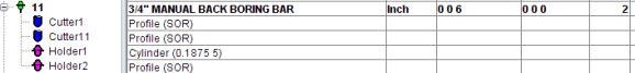
| Tool 11: Cutter1 (primary cutter) | Tool 11: Cutter11 ("alternate" cutter) |
|---|---|
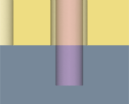 |
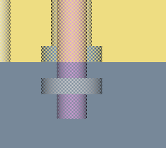 |
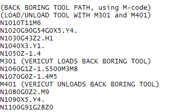
The following NC program shows how M401 and M301 are used to change between the "primary" cutter display and the "alternate" cutter display.
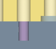
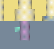
Example 2: Back boring using spindle direction to extent/retract the cutter
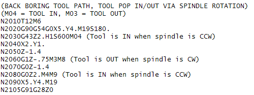
A common mechanism is to use the spindle direction to extend and retract the cutter. When the spindle is running in the CW (M03) direction the cutter is extended for cutting. When running in the CCW (M04) direction the cutter is retracted.
The following example shows how to use the "alternate" cutter feature when using spindle direction to extend and retract the cutter.
The following is the tool record in Tool Manager for a tool assembly that uses an "alternate" cutter. The "primary" and "alternate" cutter displays are also shown.

| Tool 14: Insert1 - retracted (primary cutter) | Tool 14: Insert11 - extended ("alternate" cutter) |
|---|---|
 |
 |
The following NC program shows how M4 and M3 are used to change between the "primary" cutter display and the "alternate" cutter display.
Import CAD Tool Component Models Using the CAD Geometry window
Use the procedure described below to read, extract, identify, and import tool insert and holder solid models from a CAD system into Vericut's Tool Manager. Currently, only STEP and CATIA V5 files are supported.
The following assumes the Tool Manager window is already open and that a new, or existing, tool library has been selected to add the new tool assembly, or tool component to. If necessary, refer to the following topics:
Open an Existing Tool Library File
📝 NOTE: Remember to save the Tool Library file with the modified tool information when you finish. If necessary, refer to Save a Tool Library File.
-
In the Tool Manager window, select the tool ID (in the Tool List Area) that the new tool is to be added after, or the existing tool that the imported tool component(s) are to be added to, so that it becomes highlighted.
-
In the Tool Manager Tool Bar, click on
 (Import CAD Tool) from the list to display the Import CAD Tool window.
 - Use the features in the CAD Geometry window to import a tool component(s) or tool assembly.
- In the CAD Geometry window, enter the \path\filename of the file containing the CAD model data in the CAD File text field, or click on the
 (Browse) icon to display the Select CAD File file selection window and use it to specify the \path\filename of the file containing the CAD model data.
 - In the CAD Geometry window, specify the Tool Type of the component(s) that you are importing. Choose either Mill or Turn.
- Specify the Units that you want the tool components imported in. Choose either Inch or Millimeter.
- Specify the Normals (surface normals) direction that you want use for the tool components imported in. Choose either Inward or Outward.
- Press the Load button to read the specified CAD File, identify and extract all solid bodies and then populate the table. Vericut also displays all solid bodies found in the CAD model file in Tool Manager Tool Display area.
- When the Load process finishes, the solid bodies found in the CAD model file should be listed in the CAD Geometry window, Component Table and displayed graphically in the Tool Manager, Tool Display Area.
- Click on the first record in the Component Table so that it becomes highlighted. A box will be drawn around the component in the Tool Manager, Tool display area. Use the Blank toggle for the record in the Component Table to turn on/off the graphic display in the Tool Display area to help determine what is, and is not, represented by the tool component record.
- Once you have determined what the component is, click in the Type field of the component record and select the appropriate Type from the pull-down list. Select None, Insert, Holder, or Revolved. None means that the solid body is not a tool component and will be ignored by Vericut.
-
If you identified the solid body as a Holder or None, go on to Step 13.
If you identified the solid body as an Insert, the Select Cutting Face icon will become activated. Click on the Select Cutting Face icon
so that it becomes highlighted, and then in the Tool Display Area select the loop (or edge) representing the cutting face of the insert represented by the component record.
If you identified the solid body as Revolved, the Select Revolved Axis icon will become activated. Click on the Select Revolved Axis icon to display a coordinate system on the tool in the Tool Display Area enabling you to specify the revolved cutter's axis of revolution. Click on the axis of the coordinate system displayed on the tool that represents the revolved axis. -
Repeat Steps 9 through 11 for each of the records in the Component Table.
- When you have finished identifying the components in the Component Table, use the Remove reference to CAD file in saved tool feature to specify whether to save the tool components in the imported CAD format (un-checked), or saved as a Vericut Polygon file (checked).
-
Continue with one of the following actions:
Press the Add New Tool button and Vericut will create a new tool in Tool Manager after the tool that you selected in Step 1. All of the components of Type: Insert and/or Holder will be added to the new tool.
Press the Append To Tool button and Vericut will add all components of Type: Insert and/or Holder to the existing tool that you selected in Step 1. -
Use the Close button at any time to stop the process and close the CAD Geometry window.
Examples:
Example 1 – Create a revolved profile cutter
-
Pick a CAD file.
-
Press Load.
- In the component table, pick the element and change its type to Revolved.
- Pick Select Revolved Axis and select an axis vector in the Tool Manager Tool Display graphic. Tool Manager will create a revolved profile through the axis plane you picked.
- Press Add New Tool or Append to Tool. A SOR profile cutter is created in Tool Manager. If you open the Add/Modify window for that cutter, it is shown as a Revolved Cutter (SOR). There is no reference to the original CAD geometry, regardless of whether the Remove reference to CAD file in saved tool checkbox, in the Import CAD tool window, is selected or not.
Example 2 – Create a revolved polygon cutter
-
Pick a CAD file.
-
Press Load.
- In the component table, pick the element and change its type to Revolved.
- Do not pick Select Revolved Axis.
- Press Add New Tool or Append to Tool directly. Tool Manager will create a revolved polygon cutter using the triangles from the CAD geometry. In the Tool Manager Add/Modify window, the cutter is shown as a Revolved Cutter (Model file).
- If you have the Remove reference to CAD file in saved tool checkbox toggled “on” (checked) before the cutter is created, the referenced model file is the Vericut polygon file that is created from the CAD geometry.
- Otherwise the reference model file is the CAD file itself. This is essentially the same as if you add a tool from Tool Manager, Add Tool Component > Revolved Cutter > Model file > select CAD file, except that the latter will import the whole assembly from the file.
Example 3 – Create a CAD insert cutter
-
Pick a CAD file.
-
Press Load.
- In the component table, pick the element and change its type to Insert.
- Pick faces via Select Cutting Face.
- Press Add New Tool or Append to Tool. A CAD insert is created in Tool Manager. If you open the Add/Modify window for that cutter, it is shown as an Insert Cutter (CAD). If you have the Remove reference to CAD file in saved tool checkbox toggled “on” (checked), in the Import CAD tool window, the description column in Tool Manager will show reference to the Vericut polygon file created. Otherwise the description has the reference to the original CAD file.
Example 4 - Create a polygon insert cutter
-
Pick a CAD file.
-
Press Load.
- In the component table, pick the element and change its type to Insert.
- Do not pick Select Cutting Face and press Add New Tool or Append to Tool directly. Tool Manager will create a polygon insert using the triangles from the CAD geometry. In Tool Manager Add/Modify window, the cutter is shown as an Insert Cutter (Model file).
- If you have the Remove reference to CAD file in saved tool checkbox toggled “on” (checked) before the cutter is created, the referenced model file is the Vericut polygon file that is created from the CAD geometry;
- Otherwise, the reference model file is the CAD file itself. This is essentially the same as you add a tool from Tool Manager, Add Tool Component > Insert Cutter > Model file > select CAD file, except that the latter will import the whole assembly from the file.
See Import CAD Tool window section of Tool Manager Standalone Help for additional information.
Creating Coordinate Systems for Use in Tool Manager
The following procedure assumes that the Tool Manager window has already been opened using one of the methods described in the Accessing the Tool Manager section.
Add a New Coordinate System:
-
Right-click in the Coordinate Systems List Area and select Add New CSYS from the menu that displays. A new coordinate system will be added to the Coordinate Systems List Area of the Tool Manager, and the Configure Coordinate System window will display in the center of the Tool Manager window enabling you to define the coordinate system.
-
Right-click on the default coordinate system name and select Rename in the menu that displays to rename the coordinate system.
- Use the features on the Configure Coordinate System window’s tabs to position and orient the newly created coordinate system.
- Select Add New CSYS in the Configure Coordinate System menu to add addition coordinate systems.
Any changes made on any of the Configure Coordinate System window’s tabs are applied to the coordinate system that is highlighted in the Tool Manager Coordinate Systems List Area. You can also use the Configure Coordinate System window to modify existing coordinate systems.
See Coordinate Systems List Area section of Tool Manager Standalone Help for additional information.
Add a New Coordinate System From a File:
-
Right-click in the Coordinate Systems List Area and select CSYS from File from the menu that displays.
A file selection window will display enabling you to specify the CSYS file to be used. -
Once you select the CSYS file and press OK in the file selection box, a new coordinate system is added to the Coordinate Systems List Area of Tool Manager, and the Configure Coordinate System window will display in the center of the Tool Manager window enabling you to modify the coordinate system or create additional coordinate systems.
- Right-click on the coordinate system name and select Rename in the menu that displays to rename the coordinate system.
Any changes made on any of the Configure Coordinate System window’s tabs are applied to the coordinate system that is highlighted in the Tool Manager Coordinate Systems List Area. You can also use the Configure Coordinate System window to modify existing coordinate systems.
See, Coordinate Systems List Area section of Tool Manager Standalone Help for additional information.
Modifying, Copying, or Deleting a Tool in the Library
Use the procedures below to modify, copy, or delete tools in a Tool Library file. All tasks assume that the Tool Manager window is already open and that an existing tool library has been opened. If necessary, refer to the following topics above:
Open an Existing Tool Library File
📝 NOTE: Remember to save the Tool Library file with the modified tool information when you finish. If necessary, refer to Save a Tool Library File.
Tips:
Right mouse button shortcut menus:
- Features used to manipulate tools are displayed in a shortcut menu when a tool record is selected (highlighted) and the right mouse button is clicked in the Tool List Area.
- Similarly, features used to manipulate tool components are displayed when a tool component is selected (highlighted) and the right mouse button is clicked In the Tool List Area.
Use Cut, Copy, and Paste in the right mouse button shortcut menu described above to use previously defined tool components in another assembly.
Modify an Existing Tool Component in the Library:
-
In Tool Manager’s Tool List Area, ensure the tool table shows the cutter, insert and holder components for the tool assembly. If you cannot see them, double-click the tool ID, or click on the "+" sign to expand the tool assembly in the table. You can also right-click in the Tool List Area and select Expand All in the menu that displays to expand all of the tool assemblies at one time.
-
In the Tool List Area, select the cutter, insert or holder that you want to modify so that it becomes highlighted. The appropriate Tool Definition window will display in the center of the Tool Manager window.
- Edit the data in the table as required.
See Tool Definition window section of Tool Manager Standalone Help for additional information.
Copy an Existing Tool Assembly in the Same Library:
-
In Tool Manager’s Tool List Area, select the tool ID of the tool assembly that you want to copy so that it becomes highlighted.
-
Right-click on the tool and select Copy from the menu that displays.
- Right-click the tool ID of the tool assembly that you want to paste the copied tool assembly after and then select Paste from the menu that displays.
-
A copy of the tool assembly is added to the Tool List Area after the highlighted Tool and Tool Manager assigns a default tool ID number. Right-click on the Tool and select Rename from the menu that displays.
-
Enter a unique tool ID. It is recommended that you also supply a unique Description in the Tool Manager, Tool Information tab for the new tool assembly to distinguish it from the copied tool assembly.
- Modify the tool components in the tool assembly as required. (See "To modify an existing tool component in the library" described above)
📝 NOTE: You can also use the procedure described above to copy individual tool components (cutter, insert, or holder) from one tool assembly to another within the same tool library.
Delete an Existing Tool/Tool Component from the Library:
-
In Tool Manager’s Tool List Area, right-click on the tool assembly or tool component that is to be deleted and select Delete from the menu that displays.
-
The tool assembly, or tool component, is deleted. If you deleted a tool assembly, or tool component by mistake, click on the
 (Undo) icon above the Tool List Area.
See Tool Manager window and Tool Definition window section of Tool Manager Standalone Help for additional information.