Introduction
The majority of the features described in the following sections are common to the Vericut line of products (Verification, Machine Simulation, Optimization, etc.), to Vericut Composite Simulation, and to Vericut Drill and Fastener Simulation. Any exceptions will be noted in the section in which the feature is documented.
Unless stated otherwise, the term Vericut, for example Vericut Files, used in the following sections refers to Vericut, Vericut Composite Simulation, and Vericut Drill and Fastener Simulation.
Introduction to Vericut Drill and Fastener Simulation
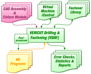
Vericut Drill and Fastener Simulation, or VDAF, reads CAD models and NC programs, either from VDAF Programming or from any programming system for any CNC-automated drilling and fastening machine.
During the simulation, drilled holes and installed fastener locations are graphically displayed. VDAF compares simulation data with data contained in a Design Locations File and reports differences between the simulated data and the design data (hole location, hole diameter, fastener type, compatibility between hole and fastener, etc.).
Reports showing simulation results and statistical information can be automatically created. The following picture illustrates the flow of data through Vericut Drill and Fastener Simulation.
Vericut Licenses and Options
In the following discussion the term "Vericut" represents Vericut, Vericut Composite Simulation and Vericut Drill and Fastener Simulation. Any exceptions will be noted within the topic.
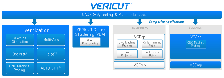
Vericut licenses and capabilities differ, depending on the environment in which Vericut is being operated. A modular approach provides the flexibility to purchase only the capabilities you need. As your needs change, you can add the appropriate licenses to increase Vericut's functionality. The terms "licenses" and "options" are synonymous, since each option for Vericut is licensed by Vericut. It is not necessary to install any additional software to add an option. Vericut provides a license that allows immediate access. See Product Line, on the Vericut website, for complete details on available options.
Vericut software licenses allow you to share Vericut over a network. Only one user may access a given license at a time. Vericut's license system supports XP, XP64, Win7, and Win7 (64). See Vericut System Requirements, on the Vericut website, for more detailed information. The server and networked workstations can be different computer types.
Licensing for Vericut
Vericut 9.7 licensing is required. If you do not have an 9.7 license, obtain licensing from Vericut as described below.
9.7 licenses are issued via email only. Your 9.7 license will be emailed to the primary Vericut user at your company. If you do not have licensing, submit an application via Vericut website.
📝 NOTE to new customers: You will need to know the computer ID (Ethernet address) of the computer on which the Vericut Network License Server is to operate. To determine the computer ID, see the steps described in the Installing Vericut Products section of the Vericut Help Library. (ref. Determine Your Host ID and Request a License).
Vericut with SpaceMouse
Vericut supports 3Dconnexion 6 axis input devices (SpaceMice) on Windows. Use of these devices requires a driver known as 3DxWare.
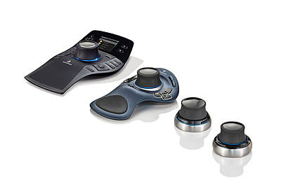
A configuration file (Vericut.scg) is required and is accessed by the 3DxWare driver on startup. This file is distributed by 3Dconnexion with the most recent version of their driver.
While beta testing has shown that Vericut generally works correctly with various older models and older versions of the device drivers, Vericut recommends using the latest driver version. It can be downloaded from https://3dconnexion.com/.
📝 NOTE: 3Dconnexion motion control devices currently work with Vericut on Windows platforms only.
Performance Considerations
In the following discussion the term "Vericut" represents Vericut, Vericut Composite Simulation and Vericut Drill and Fastener Simulation. Any exceptions will be noted within the topic.
This section describes ways to help increase Vericut productivity.
System considerations
Computer speed — Vericut runs faster on faster computers. When comparing computers made by different manufacturers, you can get a general idea how Vericut will perform by comparing the processor speed for floating point computations.
Multiple processors — Vericut runs 10-20% faster on computers with dual processors over a comparable computer with a single processor.
Memory — The amount of memory available to Vericut can make a difference. See "Vericut System Requirements" for memory recommendations. If you intend to process large tool paths, complex cutting operations, or use AUTO-DIFF, you may need more memory. Vericut uses virtual memory (hard disk) when physical memory (RAM) is exhausted. Best performance is obtained when sufficient physical memory is available to Vericut. Excessive memory does not make Vericut run faster, however, insufficient memory will slow it down.
Running concurrently with other applications — Even though your system may run Vericut or other large applications (e.g. CAD/CAM packages) comfortably, running them concurrently may cause competition for resources: memory, disk space, etc. Under these conditions the computer begins "paging" or "swapping" memory (a.k.a. "disk thrashing"), which adversely affects performance. Symptoms of disk thrashing are: constant hard drive activity or noise, active applications are slow, "Out of memory" error messages or warnings appear. In the worst case you can run out of all available memory which can cause your computer to crash or hang. When determining the amount of memory the system needs to run your applications, be sure to consider the memory requirements of ALL applications that will be run concurrently.
Graphics cards — Vericut uses 2-D raster (pixmap) graphics. It does not use triangle shading (such as with a 3-D API like OpenGL or Direct3D), texture mapping, or much (if any) vector drawing. All graphics cards (even the cheapest) do pixmap graphics. The card needs enough display or video memory to drive the display resolution at the desired number of colors. For example, 8 mb of display memory may be enough to do a 1024 x 768 display at True Color, but may only be able to do 64k colors at 1600 x 1024 resolution. Vericut 5.0 or higher performs best in a True Color display environment. More expensive does not necessarily mean "better for Vericut". Lower cost cards frequently outperform expensive cards when running Vericut.
Tolerances
The following Tolerances can be viewed and changed in the Settings window, Properties tab.
Interpolation Tolerance — This value is used to interpolate intermediate positions during NURBS, circular, and helical motions.
Rotary Motion Tolerance — The Rotary Motion Tolerance value is used with the max tessellation angle to calculate intermediate tool positions resulting from processing rotary motion. Decreasing this value increases the number of intermediate points calculated and enables Vericut to do a better job of collision detection. Tightening up this tolerance value will not significantly affect performance. This tolerance value also applies to rapid rotary motions.
📝 NOTE: The Rotary Motion Tolerance is designed to keep the tool tip within tolerance when breaking up a rotary move. The max tessellation angle (specified using the MaxTesselationAngle macro) is a better setting to use with collision detection. The number of intermediate points will be based on the maximum of these two calculation methods.
Model Tolerance — This value is used when displaying revolved models such as cylinders, cones, and revolved profiles. The accuracy of cylindrical assemblies displayed in a machine view is also affected by this value.
This value has a small effect on collision checking accuracy for revolved models used to represent machine components or fixtures.
This value is also used for the chordal deviation tolerance when a STEP model file is converted into triangles as it is being loaded into Vericut.
Location Tolerance — Use to specify the Location Tolerance. An error is reported if the distance between two location centers exceeds the sum of 2 X hole radius + Location Tolerance. Default is 2.5 mm or 0.1 inch.
Stack Gap Tolerance — Used to Specify the Stack Gap Tolerance. When the distance between two model layers exceeds the Stack Gap Tolerance, the end of the stack is assumed and the stack calculation ends. Default is 2.5 mm or 0.1 inch.
Stack Thickness Tolerance — Used to Specify the Stack Thickness Tolerance. An error is reported if the difference between the calculated model thickness, and those set by NC macros, exceeds the Stack Thickness Tolerance. Default is 5.0 mm or 0.2 inch.
Hole Diameter Tolerance — Used to specify the Hole Diameter Tolerance. An error is reported if the difference between the fastener diameter and the hole diameter set by NC macro exceeds the Hole Diameter Tolerance. Default is 0.25 mm or 0.01 inch.
Other tips and tricks
Axes display — Axes displayed in the graphics area (e.g. via Project tab > Axes or right-click shortcut menu) slow cutting speed. For best performance clear all axes before cutting.
Fixture display — Fixtures displayed in the "Workpiece" view slow cutting speed. For best performance, set Visibility to Machine View on the Component Attributes tab of the Modeling window. (e.g. via double-click on the fixture component in the Component Tree)
Skip Motion and Animation Speed control — Features on the Animation Slider directly affect cutting speed. Skipping cuts can make Vericut run faster by updating the display less frequently, especially when multi-axis cuts, large cutters, or tools with holders are involved. Also, for best performance ensure the Animation Speed slider, located at the bottom of the Vericut main window, is positioned as far right as it will go ("Fast").
No Animation — This feature, on the Project tab > No Animation, enables you to reduce processing time. When No Animation is toggled "on", the graphics display is not updated until either processing is complete or you Stop the processing. At that time the cut model is displayed in it "final" state or the state that it was in when processing was stopped. You can also toggle No Animation On/Off using the No Animation icon, ![]() , in the Vericut toolbar.
, in the Vericut toolbar.
Tool holders — Using tool holders enables Vericut to detect when non-cutting portions of the tool assembly remove material or crash into clamps/fixtures holding the workpiece. You can minimize this effect by modeling only portions of the tool assembly that can be involved in a collision. For example, don't bother modeling the taper of a milling tool holder (portion that seats inside the spindle). If you don't have concerns about tool holder collisions, Vericut will run faster if tool holders are not displayed, e.g.: Project Tree > Configure Tooling menu > Holder Visibility feature clear the "Display Holders in Workpiece View" checkbox.
Status and NC Program panels — Opening these panels via the Info tab provides valuable information about the machining process. However, since Vericut updates them with each NC Program record processed, having them open while cutting slows performance. For best performance, close them before cutting. You can reopen them later, as needed for reference.
Address unsupported codes in G-Code tool paths — When processing G-Code tool paths, "unsupported" codes cause messages to be written to the Vericut Log file and the Vericut main window message area. Reporting numerous unsupported codes can slow performance dramatically. Avoid writing "false" errors and the corresponding time loss by addressing unsupported codes via the NC control configuration. To ignore codes that are unimportant to the simulation, use Machine/Control tab > Word/Address to add groups that will have unsupported codes call the macro, IgnoreMacro.
Faster zooming — Following is a technique to improve the zoom and display speed, and eliminate the post zoom delay between pressing Play and resuming cutting. Create a second, smaller view window (View tab > Add View) and position it to the side. Cut the part. When you want to see an area in more detail, use the smaller window for zooming. This protects the refined display in the larger window. Because Vericut needs only to update the smaller image, you get zoom images much faster than performing the operation in the larger window. Also, when you restart the simulation there is virtually no delay before Vericut starts cutting again.
Disable Report — This feature on the Analysis tab > AUTO-DIFF window: Settings tab enables you to turn off the AUTO-DIFF Report feature to reduce AUTO-DIFF processing time. For large NC program files, generating the report can take a significant amount of time. When toggled "off", you will still see the AUTO-DIFF results in the graphics area.
Want more Vericut tips and tricks from the experts? Visit the Vericut web site at https://vericut.com and click "SUPPORT", then look for "Tech Tips".
Using Mathematical Equations/Expressions in Vericut
In the following discussion the term "Vericut" represents Vericut, Vericut Composite Simulation and Vericut Drill and Fastener Simulation.
Equations/expressions can be used in any data field within Vericut where a numeric value is expected. They can be used for "single value" data fields like the Increment value in the Project Tree Configure Model menu illustration below. The can also be used for "triplet value" data fields like the Position values shown in the illustration. When using triplet value data fields separate the equations/values with a blank space.
![]()
EXAMPLES:
| Equation / Expression | Value as interpreted by Vericut |
|---|---|
| sqrt(sqr(4.5) + sqr(2.3) + sqr(6.5)) | 8.2334 |
| trunc(543.6544) | 543 |
| Ec | 2.718282 |
| 1.256 ** 1.2 | 1.3145 |
| ec ** (1.2 * log(1.256)) | 1.3145 |
| a = acos(⅗) | 53.1301 |
| b = asin(⅘) | 53.1301 |
| c = 2 * 3 * 5 | 30 |
| sqrt(sqr(3) + sqr(5) - c * cos(a)) | 4 |
| pi | 3.141593 |
The following mathematical functions/features are available for use within equations/expressions in Vericut:
| MATHEMATICAL FUNCTION/FEATURE | DESCRIPTION |
|---|---|
| + | Addition |
| - | Subtraction |
| * | Multiplication |
| / | Division |
| mod | Modulus |
| ^ or ** | Exponentiation |
| (, [ or { | Left Parenthesis |
| ), ] or } | Right Parenthesis |
| sqr or square | Square |
| sqrt or root | Square Root |
| abs | Absolute Value |
| int or trunc | Integer Part |
| frac | Fractional Part |
| nint | Nearest Integer |
| pi | Ratio of circle circumference to diameter |
| sin | Sine (argument in degrees) |
| cos | Cosine (argument in degrees) |
| tan | Tangent (argument in degrees) |
| asin | Inverse Sine (result in degrees) |
| acos | Inverse Cosine (result in degrees) |
| atan | Inverse Tangent (result in degrees) |
| atan2(y:x) | Inverse Tangent (result in degrees) |
| sinh | Hyperbolic Sine |
| cosh | Hyperbolic Cosine |
| tanh | Hyperbolic Tangent |
| e or ec | Euler's Constant |
| log | Natural Logarithm |
| analog or exp | Natural Anti-Logarithm |
| log10 | Base 10 Logarithm |
| alog10 | Base 10 Anti-Logarithm |
| fac | Factorial |