Travel Limits Branch
Right-click on a Travel Limits Branch in the Project Tree panel to display the following menu:
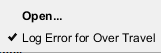
Open — Opens the Collision and Travel Limits window, Travel Limits tab enabling you to specify the valid range of travel for each machine axis, and control when travel limit errors are detected.
Log Error for Over Travel — Toggles Log Error for Over Travel “on” (checked), to start machine travel limit checking, and “off”.
Collision and Travel Limits window
Locations:
Project Tree > Collision Branch Right Mouse Shortcut Menu > Open
Project Tree > Travel Limits Branch Right Mouse Shortcut Menu > Open
The features on the Collision and Travel Limits window enable you to configure the settings required for processing G-Code NC program files related to detecting collisions between machine components and detecting when a machine axis limit has been exceeded.
Collision Detect tab — Features on this tab control when collisions between machine components are detected, which components are protected, and tolerances used for detecting collisions.
Travel Limits tab — Features on this tab define how far each machine axis can go, and control when travel limit errors are detected.
Apply — Applies the changes and leaves the Collision and Travel Limits window open.
Close — Closes the Collision and Travel Limit window without applying changes.
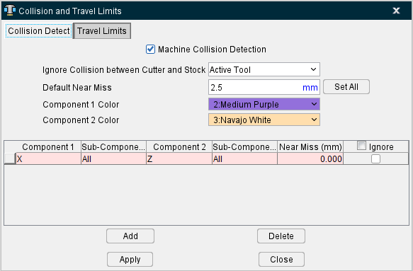
Collision and Travel Limits window, Collision Detect tab
Features on the Collision Detect tab enable you to control when collisions between machine components are detected, which components are protected, and specify the tolerances used for detecting collisions.
Colliding components are highlighted using the red Error color, and errors are issued to the Log file identifying collision causing block(s) and machine components.
Machine Collision Detection — When toggled "On", detects collisions between specified components.
Ignore Collision between Cutter and Stock — Controls when collisions between the cutter and the Stock component are ignored. This feature is useful when collision detection is desired between the stock and shank or holder portions of the tool assembly in the machine view, but not with the cutter.
Options are:
-
No — (default) Does not ignore cutter-stock collisions. All collisions are reported.
-
All Tools — Ignores cutter-stock collisions for all tools, even inactive tools in multi-tool machines.
-
Active Tool — Ignores cutter-stock collisions for the active tool. However, collisions between stock and inactive tools are detected.
Default Near Miss — Specifies the default collision tolerance applied to all collision cases when Set All is pressed (see below).
Component ½ Color — These dropdown fields are used to set the colors of the first and second component involved in collisions so you can visually see where collisions are occurring more easily.
Set All — Sets the default collision tolerance for all collision cases to the Default Near Miss value. You can edit the supplied tolerance for individual cases.
Component/Component collision list
Lists the component-to-component collision cases that are checked when collision detection is turned on.
📝 NOTES:
-
Records displayed in pink are created, and modified, using the Machine Settings window: Collision Detect tab (Machine/Control tab > Machine Settings > Collision Detect tab) and saved in the machine file.
The Machine Settings window: Collision Detect tab and the Collision and Travel Limits window: Collision Detect tab (Project Tree: Collision branch right mouse button menu > Open) are linked so that whenever additions or changes are made in the Machine Settings window: Collision Detect tab they are also updated in the Collision and Travel Limits window: Collision Detect tab.
Pink records cannot be modified in the Collision and Travel Limits window: Collision Detect tab. -
Records displayed in white are part of the setup and can be created, or modified, in the Machine Settings window: Collision Detect tab or in the Collision and Travel Limits window: Collision Detect tab and are saved with the setup in the project file.
These two windows are linked so that whenever additions, or changes, are made to white records in one window they are updated in both windows when you select Apply or OK.
Component1/Component 2 — Use these features to specify the component-to-component collision cases to check. The Near Miss value controls how close the components are permitted to be before reporting a collision. Clicking on a component field in a record displays a pull-down list of component to choose from.
📝 NOTE: Do not configure for collision detection between components that move (slide or rotate) against each other, such as connected motion axes. In these cases, errors may occur each time the components move.
Sub-Components — Toggle On/Off to include Sub-Components of Component1/Component2 during collision checking.
Near Miss — Use to specify the tolerance to use for collision checking. Enter a positive value to be alerted if components come near each other within the specified clearance, zero to indicate components may not touch, or a negative value if components are expected to collide by the specified value.
📝 NOTE: "Near Miss" tolerances are not supported for collision checking against the cut model. The accuracy of collisions with the cut stock is dependent on the "Cutting Resolution".
Ignore — When toggled “on” (checked), Vericut will ignore the specific collision record during collision checking. Ignore, when toggled “on”, only remains active for the current session. It is not saved in the project file.
Add — Adds a new collision case record to the list. The new record is added after the highlighted record.
Delete — Deletes the selected collision case record from the list. Records displayed in pink come from the machine file and cannot be deleted.
↘️ Shortcut: You can right-click in the Component/Component collision list to display a menu containing Add and Delete. These provide the same functionality described above.
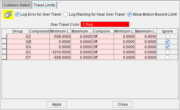
Collision and Travel Limits window, Travel Limits tab
Features on the Travel Limits tab enable you to specify how far each machine axis can go, and control when travel limit errors are detected.
Overtravel errors cause the violating machine component to "light up" in the Overtravel Color and errors are output to the Log file identifying the problem component.
Log Error for Over Travel — When active, turns on over travel detection (travel limit checking). Components that move beyond specified limits are highlighted in the Overtravel Color and errors are issued to the Log file identifying error causing block(s) and machine components.
Log Warning for Near Over Travel — When active, turns on over travel detection (travel limit checking). Components that move beyond specified limits are highlighted in the Overtravel Color and errors are issued to the Log file identifying error causing block(s) and machine components. Two additional columns will also generate in the Travel Limit Record Table as well.
Allow Motion Beyond Limit — When toggled "on", axes are allowed to freely travel beyond defined limits. When toggled "off", an axis is never allowed to travel beyond the defined limit.
Overtravel Color — Use to specify the color in which components that move past their specified limits are shaded. Available shade colors are defined on the Configuration tab > Colors: Define tab.
Travel Limit Record Table
List of travel limit records in which each record consist of a group number, motion component (and its axis limits), travel limit condition and an ignore switch. These records come from the machine file and cannot be edited.
Group — Indicates the travel limits record group that is currently active A specific group is of travel limit records is activated by using the TravelLimitsGroup macro. For information on the TravelLimitsGroup macro, and all Vericut macros, see Vericut Macros in the Vericut Help Library.
Component — Indicates a motion component for travel limit checking.
Minimum / Maximum — Indicates the minimum, and maximum, travel limits for the motion axis specified in the record.
The next three columns in the Travel Limit Record Table indicate conditions when the travel limit record is used. The condition can be set to "off" indicating no special condition for this record or set to a motion component on the machine.
When a motion component is specified, then the travel limit record is used if the axis of the conditional component is within the conditional minimum and maximum limit values.
Component (C) — Indicates a condition when the travel limit record is used. It is set to "off" to indicate no special condition for this record, or to a conditional motion component on the machine.
Minimum (C) / Maximum (C) — Indicates the minimum and maximum travel limits for the conditional motion component (Component (C)) that will cause the travel limit record to be used.
Near Min. Warning / Near Max. Warning — Indicates the minimum and maximum thresholds for receiving near travel warnings. These columns will only appear when Log Warning for Near Over Travel is active.
Ignore — When toggled "on", over travel checking is ignored for the corresponding axis.