The Project Tree
Location:
Project tab >  (Project Tree)
Toolbar short cut: ![]()
Introduction to the Project Tree
The features on the Project Tree provide the tools required for the day to day use of Vericut for setting up jobs for verification and simulation. The following basic concepts are needed to understand the process of setting up a job for Vericut.
Project — A project consists of one or more setups (see Setup below) enabling you to simulate multiple operations in a single Vericut session. Multiple Setups within a project can use the same, or different, machines. A Project with a single Setup is logically equivalent to the User file of past Vericut releases.
Setup — A Setup is a collection of Vericut settings and files (machine, control, tool library, etc.), NC program files, and Setup models (Stock, Fixture, Design) that define the machine operation to be simulated. A Setup is logically equivalent to the User file of past Vericut releases.
Current Setup — The Setup menu choices such as CNC Machine, NC Programs, etc., apply only to the Current Setup. A setup can be designated "current" either by selecting it using the Current Setup option in the Project menu, or by selecting it in the Project Tree. The "current" setup is indicated by a checkmark in the Current Setup menu and is displayed as bold in the Project Tree (See Setup 3 in the picture above).
Active / Inactive Setup — A Setup can be designated as being in either an Active, or Inactive state. When a Setup is designated as Inactive, it is not simulated, as if it were not present in the overall process. An Inactive setup can however be designated as the "current" setup and modified. Inactive Setups are indicated by red text in both the Current Setup menu and in the Project Tree (See Setup 2 in Project Tree Example 2 below).
The Project Tree panel
The features on the Project Tree provide the tools required for the day to day use of Vericut for setting up jobs for verification and simulation. The following basic concepts are needed to understand the process of setting up a job for Vericut.
The Project Tree panel is one of the dockable panels enabling you to dock it inside the Vericut main window if you choose. See Personalizing the Vericut Main Window section of Vericut Help for additional information.
📝 NOTE: When the Project Tree panel is docked, make sure that you click in the panel so that it becomes the "active" panel before using F1 to get help specific to the panel. Otherwise F1 will go to the Vericut Help Library.
 (Close) — Located at the end of the tab, this icon enables you to close the Project Tree panel.
 (Close) — Closes the Program panel. This icon is only displayed when the NC Program panel is not docked.
Top Icon Bar:
![]()
The six icons at the top of the Project Tree panel enable you to control when picks in the Vericut graphics area are applied to the Project Tree, what information is displayed in the Project Tree, “undo” and “redo” Project Tree changes, and to close the Project Tree completely. Placing the cursor over each of the icons displays a tip indicating what the icon is used for. The tip that will display for each icon is displayed in bold text next to the icon in each of the descriptions below. The function of each of the icons is described below:
 (Mouse active to enable mouse tracking and picks, inactive to disable.) — Use this icon to designate that the NC Program Review panel is the panel that picks in the Vericut graphics area are to be applied to. When “Active”, the icon is displayed in the Mouse Pick Highlight Color specified in the Configuration tab > Preferences window. When “Inactive”, the icon is displayed.
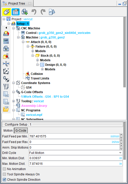
 (Configure) — Use this icon to toggle the Configure menu feature “on” and “off”. When toggled “on”, the appropriate Configure menu for the selected item in the Project Tree will be displayed at the bottom of the Project Tree. The picture below shows that a Setup branch has been selected and the Configure Setup menu is displayed at the bottom of the Project Tree. Each of the Configure menus, with all of its features, is described in detail in the Configure section.
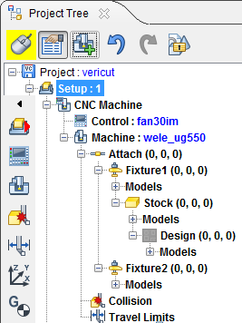
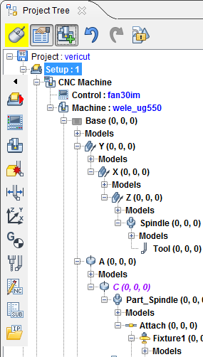
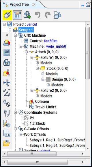
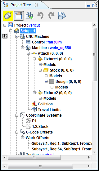
 (Show Machine Components) — Use this icon to toggle the Show Machine Components feature “on” and “off”. When toggled “on”, machine components are displayed the Project Tree similar to the way that they were displayed in the Component Tree in previous Vericut versions. The following pictures show the difference in the Project Tree when this feature is toggled “on” and “off”.
| Show Machine Components toggled “off” | Show Machine Components toggled “on” |
|---|---|
 |
 |
📝 NOTE: In some environments, the Show Machine Components icon will not be displayed in the Project Tree. This is because the CGTECH_MACHINE_CONFIG environment variable has been set in the vericut.bat file to restrict access to Vericut’s machine configuration features.
-
 (Undo) — Use this icon to “undo” changes made in the Project Tree. The icon will be grayed out until a change is made in the Project Tree. Once a change is made in the Project Tree the icon will display as shown here. Click on the icon to “undo” the last change made to the Project Tree. Click on the icon again to “undo” the next to the last change and so on. There is no limit to the number of changes that you can “undo”.
 -
 (Redo) — Use this icon to “redo” changes that you have used the Undo feature on. The icon will be grayed out until the Undo feature is used. Once the Undo feature is used, the icon will display as shown here. Click on the icon to “redo” the last “undo”. Click on the icon again to “undo” the next to the last “undo” and so on. There is no limit to the number of “undo” actions that you can “redo”.
 -
 (Lock Models) — Use this icon to lock the models in place. When the models are locked, the icon changes to
  .
.
When the Lock Models icon is unlocked, the following activities are available:
-
Change Component Attachments
-
Components, including all children components and models, can be dragged and dropped anywhere in the tree.
-
Copying and pasting a selected component copies and pastes all of the children components and models.
-
Change Model Attachments
-
Models can be dragged and dropped anywhere in the component subbranch it is relative to.
-
Copying and pasting selected models only copies and pastes them relative to their original component subbranch.
-
Change Component Location
-
When a component’s position or rotation is altered, all of the models and sub-components change with it.
When the Lock Models icon is locked, the above activities are disabled and the following goes into effect:
-
Change Component Attachments
-
Dragging and dropping a component and all of their children components, does not change any of the component model’ absolute machine position. The models visually remain in the same place.
-
Copying and pasting components and all of their children does not change any of the component models’ absolute machine position
-
Change Model Attachments
-
Dragging and dropping models does not change the models’ absolute machine position. The models visually remain in the same place.
-
Copying and pasting models does not change the models’ absolute machine position.
-
Change Component Location
-
Changing a component’s position or rotation keeps all of the models of the current component and all of its children components in the same absolute machine position. Models do not have to be moved manually to the previous positions.
(Close) — Use this icon to close the Project Tree.
The Project Tree shows all Setups and each Setup's configuration in a tree hierarchy. A project can consist of one or more setups. Vericut processes each "active" setup sequentially, starting at the top of the tree. The functionality available in the Project Tree duplicates the functionality available in the Project tab, but in a more visual tree format.
Side Icon Bar:
| Image | Explanation |
|---|---|
| The icons in the Side Icon Bar enable you to quickly move to a particular setup, or “branch” in the “current setup. Each of the icons is defined in more detail below. Holding the cursor over any of the icons displays a tip showing the “branch” that the icon will go to. |
The Side Tool Bar can be hidden and re-displayed, for better Project Tree navigation. Click on the  button at the top of the Side Tool Bar to hide it. Click on the
  button to re-display it.
| Before | After |
|---|---|
 |
 |
![]() (Setup) — Click in the Setup icon to display a pull-down list of setups available in the current project file. Select the desired setup from the list and the selected setup branch becomes highlighted and the setup becomes the “current” setup.
(Setup) — Click in the Setup icon to display a pull-down list of setups available in the current project file. Select the desired setup from the list and the selected setup branch becomes highlighted and the setup becomes the “current” setup.
![]() (Control) — Click on the Control icon and the Control branch in the “current” setup becomes highlighted. Double-click on the Control icon to open the Open Control window enabling you to open (load) a Control file.
(Control) — Click on the Control icon and the Control branch in the “current” setup becomes highlighted. Double-click on the Control icon to open the Open Control window enabling you to open (load) a Control file.
![]() (Machine) — Click on the Machine icon and the Machine branch in the “current” setup becomes highlighted. Double-click on the Machine icon to open the Open Machine window enabling you to open (load) a Machine file.
(Machine) — Click on the Machine icon and the Machine branch in the “current” setup becomes highlighted. Double-click on the Machine icon to open the Open Machine window enabling you to open (load) a Machine file.
![]() (Collision) — Click on the Collision icon and the Collision branch in the “current” setup becomes highlighted. Double-click on the Collision icon to open the Collision and Travel Limits window: Collision Detect tab enabling you to configure the settings required for processing G-Code NC program files related to detecting collisions between machine components.
(Collision) — Click on the Collision icon and the Collision branch in the “current” setup becomes highlighted. Double-click on the Collision icon to open the Collision and Travel Limits window: Collision Detect tab enabling you to configure the settings required for processing G-Code NC program files related to detecting collisions between machine components.
![]() (Travel Limits) — Click on the Travel Limits icon and the Travel Limits branch in the “current” setup becomes highlighted. Double-click on the Collision icon to open the Collision and Travel Limits window: Travel Limits tab enabling you to configure the settings required for processing G-Code NC program files related to detecting when a machine axis limit has been exceeded.
(Travel Limits) — Click on the Travel Limits icon and the Travel Limits branch in the “current” setup becomes highlighted. Double-click on the Collision icon to open the Collision and Travel Limits window: Travel Limits tab enabling you to configure the settings required for processing G-Code NC program files related to detecting when a machine axis limit has been exceeded.
![]() (Coordinate Systems) — Click on the Coordinate Systems icon and the Coordinate Systems branch in the “current” setup becomes highlighted. Double-click on the Coordinate Systems icon to highlight Coordinate Systems branch in the “current” setup and expands the Coordinate Systems branch so that all of the Coordinate Systems in the branch are shown.
(Coordinate Systems) — Click on the Coordinate Systems icon and the Coordinate Systems branch in the “current” setup becomes highlighted. Double-click on the Coordinate Systems icon to highlight Coordinate Systems branch in the “current” setup and expands the Coordinate Systems branch so that all of the Coordinate Systems in the branch are shown.
![]() (G-Code Offsets) — Click on the G-Code Offsets icon and the G-Code Offsets branch in the “current” setup becomes highlighted. Double-click on the G-Code Offsets icon to highlight G-Code Offsets branch in the “current” setup and expands the G-Code Offsets branch so that all of the G-Code Offset records in the branch are shown.
(G-Code Offsets) — Click on the G-Code Offsets icon and the G-Code Offsets branch in the “current” setup becomes highlighted. Double-click on the G-Code Offsets icon to highlight G-Code Offsets branch in the “current” setup and expands the G-Code Offsets branch so that all of the G-Code Offset records in the branch are shown.
![]() (Tooling) — Click on the Tooling icon and the Tooling branch in the “current” setup becomes highlighted. Double-click on the Tooling icon to open the Tool Manager window enabling you to create and maintain Tool Library files containing descriptions of cutting tools, or tool assemblies.
(Tooling) — Click on the Tooling icon and the Tooling branch in the “current” setup becomes highlighted. Double-click on the Tooling icon to open the Tool Manager window enabling you to create and maintain Tool Library files containing descriptions of cutting tools, or tool assemblies.
![]() (NC Programs) — Click on the NC Programs icon and the NC Programs branch in the “current” setup becomes highlighted. Double-click on the NC Programs icon to open the NC Programs File Selection Window enabling you to add one or more NC program files.
(NC Programs) — Click on the NC Programs icon and the NC Programs branch in the “current” setup becomes highlighted. Double-click on the NC Programs icon to open the NC Programs File Selection Window enabling you to add one or more NC program files.
![]() (NC Subroutines) — Click on the NC Subroutines icon and the NC Subroutines branch in the “current” setup becomes highlighted. Double-click on the NC Programs icon to open the NC Subroutine Files File Selection Window enabling you to add one or more NC subroutine files.
(NC Subroutines) — Click on the NC Subroutines icon and the NC Subroutines branch in the “current” setup becomes highlighted. Double-click on the NC Programs icon to open the NC Subroutine Files File Selection Window enabling you to add one or more NC subroutine files.
![]() (Saved IP Files) — Click on the Saved IP Files icon and the Saved IP Files branch in the “current” setup becomes highlighted. Double-click on the Saved IP Files icon to highlight Saved IP Files branch in the “current” setup and expands the Saved IP Files branch so that all of the IP files in the branch are shown.
(Saved IP Files) — Click on the Saved IP Files icon and the Saved IP Files branch in the “current” setup becomes highlighted. Double-click on the Saved IP Files icon to highlight Saved IP Files branch in the “current” setup and expands the Saved IP Files branch so that all of the IP files in the branch are shown.
![]() (Drilling and Fastening) — Click on the Drilling and Fastening icon and the Drilling and Fastening branch in the "current" setup becomes highlighted and is expanded to display the Fastener Models branch which is also expanded and the Design Locations and Simulated Locations branches.
(Drilling and Fastening) — Click on the Drilling and Fastening icon and the Drilling and Fastening branch in the "current" setup becomes highlighted and is expanded to display the Fastener Models branch which is also expanded and the Design Locations and Simulated Locations branches.
The following examples describe some of the information available to you from the way that the items in the Project Tree are displayed.
![]() (Tape Head) — Once pressed, this Tape Head short cut will display a drop down of all tape heads in the project. Component type must be Tape Head in the Configure Component Panel. The format displayed is "[setup index]: [tape head name]". You can click on one of the drop down tape heads to quickly select it in the Project Tree.
(Tape Head) — Once pressed, this Tape Head short cut will display a drop down of all tape heads in the project. Component type must be Tape Head in the Configure Component Panel. The format displayed is "[setup index]: [tape head name]". You can click on one of the drop down tape heads to quickly select it in the Project Tree.
Project Tree Example 1: "New" Vericut project with a single setup.
| Image | Explanation |
|---|---|
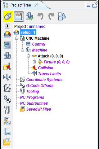 ______________________________________________________ ______________________________________________________ |
The picture at the left shows the Project Tree for a "new" project containing a single setup. Since it is the only setup, it is by default the "current" setup, indicated by the bold text. The red text here indicates that no data has been assigned to any of these items. The initial machine is defined with Attach, Fixture, Stock, and Design components but no models have been assigned |
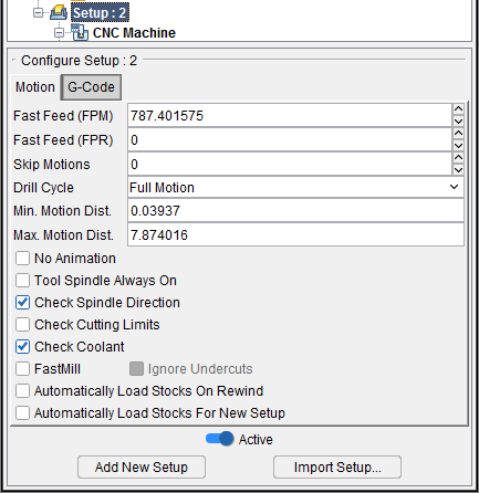
Project Tree Example 2: This example shows a Vericut project with multiple setups.
| Image | Explanation |
|---|---|
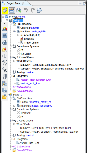 __________________________________________________________ __________________________________________________________ |
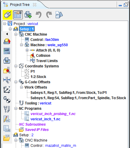
The picture at the left shows the Project Tree for a three setup job. Setup: 1 is displayed in black text indicating that it is in an "active" state. The bold text indicates that Setup 1 is the "current" setup. The Collision, Travel Limits, NC Subroutines, and Saved IP Files labels in Setup: 1 are displayed in red text indicating that these features are not being used for Setup 1. All of the items in Setup: 2 are displayed in red text indicating that Setup 2 is in an "inactive" state. Setup: 3 is displayed in plain black text indicating that it is in an "active" state but is not the “current” setup. NC Subroutines and Saved IP Files are not used in this setup. |
Each item in the Project Tree has a Right Mouse Button Shortcut menu containing features specific to the particular item. Click with the right mouse button on the branch or item in the Project Tree to display the menu.
In addition, if the Configure feature is toggled “on”, clicking with the left mouse button will display a window containing the features that applicable to the particular Project Tree branch.
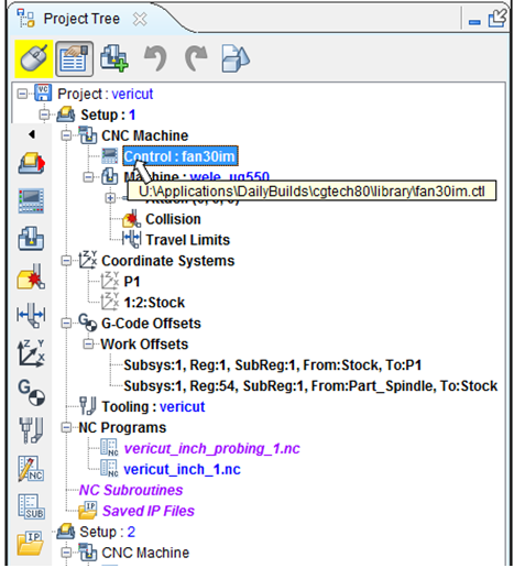
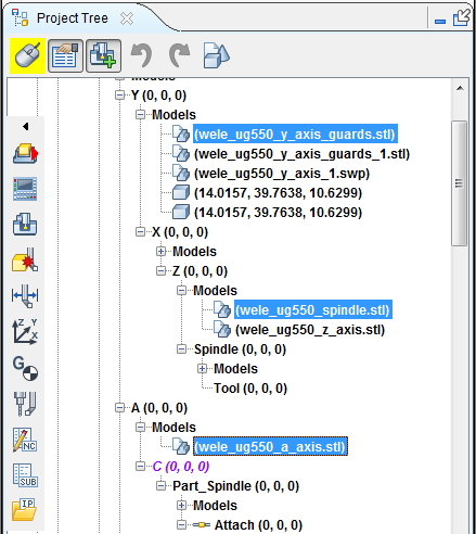
Each item in the Project Tree that has a file associated with it (models, NC programs, Machine files, Control files, etc.) which shows the file name next to it as shown in the picture below.
If you hold the cursor over the file name, the full /path/filename will display as shown in the picture below.
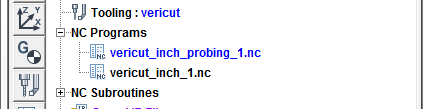
The "current" NC program is displayed in blue text as shown in the picture below.
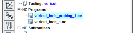
When the "current" NC program is actually processing it is also highlighted in blue as shown in the picture below.
Manipulating Multiple Objects in the Project Tree
You have the ability to select multiple Project Tree objects as long as you adhere to the following guidelines.
- Only the following branch types allow multiple selections.
-
Component
-
Models
- Coordinate Systems
- NC Programs
-
NC Subroutines
-
Each branch type is mutually exclusive, meaning that you cannot select multiple objects from under different branch types. For example, you can select multiple models under different Models branches as shown in the picture below.
But you cannot select objects under different branch types. For example selecting multiple NC programs and multiple NC Subroutines in the same selection sequence is not allowed.
-
You can only make multiple selections within a single Setup. To select multiple objects in the Project Tree, try these techniques:
-
Select multiple files in sequence — Click the first object in the sequence, then press and hold the \<Shift> key while clicking on the last object in the sequence. The first, last and all objects between will become highlighted.
-
Select additional individual files — Press and hold the \<Control> key while selecting each additional object. Each will become highlighted.
With either method, selecting an object a second time, while holding down the \<Control> key, un-selects the object.
Simply clicking on a highlighted object a second time will not un-select the object. Holding the cursor over the highlighted object after clicking on it will put it in "edit" mode.
You can select objects either in the Project Tree or in the graphics area. Selecting an object in the Project Tree will highlight the object in the Project Tree and display a three dimensional wireframe box representing the bounds of the corresponding object in the graphics area. Selecting an object in the graphics area will display a three dimensional wireframe box representing the bounds of the selected object in the graphics area and highlight the corresponding object in the Project Tree.
Once the objects have been selected, the actions that are available are dependent on the object type.
-
Selected Components, Models, or Coordinate Systems can be translated or rotated. Child components of these objects are not translated or rotated.
-
Selected NC programs can be made "Active" or "Inactive".
You can "Drag" and "Drop" selected branches or objects from one location to another. For example, you can "move" or "copy" selected NC subroutines from one Setup to another.
- To "move" selected objects; click on the highlighted objects and keeping the left mouse button depressed "drag" the objects to the desired location and release the mouse button to "drop" the selected objects.
Drag and Drop Files from Windows Explorer to the Project Tree
You have the ability to drag one or more files from a Windows Explorer window and drop them into the Project Tree and have them be loaded it to Vericut. Supported file types are: Project Files, In-Process (IP) Files, Control Files, Machine Files, Model Files, Tool Library Files, NC Program Files, and NC Subroutine Files.
In the Windows Explorer window, select a compatible file and drag it to the Vericut Project Tree panel. Most supported files can be dragged and dropped anywhere in the Project Tree panel in order to load. Machine Files and NC Subroutine Files must be dragged and dropped to the their respective branches in order to load.
Using the Project Tree
The basic philosophy of the Project Tree is that it enables you to configure a project’s setups using the Project Tree features as a guide, as follows: * Use the Project Tree to step down through the tree structure, configuring each branch of a setup as you go.
- A “Configure” panel is optionally displayed at the bottom of the tree’s dialog during setup configuration.
- The “Configure” panel displays settings and actions most commonly used for configuring the setup.
- The features on each “Configure” panel are specific to the branch or item selected in the tree.
- Widgets in the panel cause an immediate action when used. There is no OK, Apply, etc.
- Less commonly used features are available in the right-mouse button shortcut menus associated with each branch or item selected in the tree or from pop-up dialogs accessed from the Vericut Menu ribbon.
Project Tree Right Mouse Button Shortcut Menus
Each item in the Project Tree has a right mouse button shortcut menu (RMB menu) containing features specific to the particular item.
📝 NOTE: Any item shown in bold in a Project Tree right mouse button shortcut menu can also be reached directly by double clicking on the item (branch, component, model, etc.) in the Project Tree that you right -clicked on to display the shortcut menu. For example, double-clicking on the Project branch in the Project Tree displays the Open Project window, just like clicking on Open in the shortcut menus.