Configure Component menu
Location:
Project Tree > Component branch (Configure "on")
If the applied movement is incorrect, press the Undo icon in the Project Tree Top Icon Bar to return the object to its previous location.
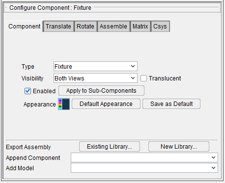
Component tab — Features on the Component tab are used to define the attributes of a component. The features that are available on the Component tab will vary depending on the Component Type. Each of the variations is described in the Component Types section.
Vericut handles components and their solid models differently depending on the component's type and attributes. Most attributes apply to components used in building NC machines.
Translate tab — Features on this tab translate the selected object via indicating "from" and "to" points to move the object. Movement occurs each time you press the Move button.
Rotate tab — Features on the Rotate tab rotate the selected object about a rotation center point.
Assemble tab — Features on the Assemble tab move the object by assembling (mating or aligning) it with other objects.
Matrix tab — Features on the Matrix tab enable you to move a selected component/model from one coordinate system to another.
Csys tab — Features on the Csys tab enable you to move a selected component/model from one coordinate system to another.
Export Assembly — Export Assembly copies the selected component and its children to an Assembly and saves it to an assembly library file.
-
Existing library… — Opens a file selection box to select which file to add the Assembly to and saves the file.
-
New library… — Opens a file selection box to create a new library file and saves the Assembly to it. If the name of the library file already exists, it will be replaced.
Append Component — The items displayed in the Append Component pull-down list will differ depending on the component type currently selected (highlighted) in the Project Tree.
When an Attach component, or a project component (those component types displayed when the Show Machine Components feature is toggled "off") is selected, only the component types that are valid “project” components will be displayed in the list. Click on the arrow button ![]() and select from the following "project" component types:
and select from the following "project" component types:
-
Deflector — The Deflector component represents the deflectors used for water jet machining.
-
Design — The Design component represents a solid or surface representation of the theoretical designed part.
-
Design Point — The Design Point component represents a point representation of the theoretical designed part.
-
Electrode — The Electrode component represents the electrodes used for Die Sinking Simulation (EDM machining).
-
Fixture — When using Vericut, the Fixture component represents the hardware used to hold the workpiece for machining, such as: base plates, clamps, bolts, vises, pallets, etc.
-
Skin — The Skin component is where holes are drilled. Only one skin component is allowed for each setup. If multiple skin components exist, only the first one is used and the rest are ignored. This component is only used for Vericut Drilling and Fastener Simulation.
-
Stock — The Stock component represents the workpiece that is to be machined. This component type must be present in all simulations.
-
Structure — The Structure component defines the structure that the skin component is fastened to. Only the Skin component and the Structure components are used for stack analysis. All other component types are ignored. Structure component and its models have "Material" settings that are checked against the material specified in the NC program. This component is only used for Vericut Drilling and Fastener Simulation.
-
X Track — Used for Electroimpact FlexTrack machines. Behaves like an X Linear component.
-
Y Track — Used for Electroimpact FlexTrack machines. Behaves like a Y Linear component.
-
Z Track — Used for Electroimpact FlexTrack machines. Behaves like a Z Linear component.
The selected component is added to the Project Tree after, and as a child of, the highlighted component.
When a "machine" component (those component types displayed only when the Show Machine Components feature is toggled "on") is selected, only the component types that are valid "machine" components will be displayed in the list. Click on the arrow button and select from the following “machine” component types:
 -
X Linear, Y Linear, Z Linear — Linear motion axes on an NC machine. Motion axes are parallel to X, Y, Z axes, respectively-but this can be changed via the Motion Axis component attribute.
-
A Rotary, B Rotary, C Rotary — Rotary motion axes on an NC machine. The component origin is the pivot point of rotation. By default, rotation occurs about the X, Y, Z axes, respectively-but this can be changed via the Motion Axis component attribute.
-
U Linear, V Linear, W Linear — Co-linear motion axes on an NC machine. Motion axes are parallel to X, Y, Z axes, respectively-but this can be changed via the Motion Axis component attribute.
-
A2 Rotary, B2 Rotary, C2 Rotary — Secondary rotary motion axes on an NC machine. The component origin is the pivot point of rotation. By default, rotation occurs about the X, Y, Z axes, respectively-but this can be changed via the Motion Axis component attribute.
-
A Turret, B Turret, C Turret — Indexing tool turret that rotates about X, Y, or Z axes. Like rotary components, the turret component origin is the pivot point for rotary indexing. The presence of these components cause all connected tools to be displayed making it possible to detect collisions resulting from turret indexing. A Turret component is commanded to move using a tool change command (e.g. Tn). The turret indexes based upon activating a Tool component connected to the turret. Tool component orientation determines the tool index position in the turret. Rotary control settings determine how turrets rotate, e.g.: rotation direction, etc.
-
Turret — The Turret component does not use an axis and is intended to replace the A Turret, B Turret and C Turret components.
-
Gang Tooling Post — A Gang Tooling Post component is a component that holds several cutting tools in a row. The Gang Tooling Post is not a motion component; it does not index/rotate into position. Use a Gang Tooling Post component to:
To define a component that holds tools. A Gang Tooling Post component does not use a turret enabling you to directly configure a gang tooled machine. The Gang Tooling component does not rotate (only carries tools).
To define the subsystem associated with tools.
📝 NOTE: Tools inherit their subsystem id from a parent component where the subsystem is defined).
To assist in defining offsets. The Gage Pivot offset (or in old controls, the turret offset) can be used to define the offset from the active tool to the Gang Tooling Post origin. A Program Zero offset (or a Work Offset) can then be defined from the Gang Tooling Post to the Program Zero point on the part. -
Spindle — Spindle on an NC machine. The function of this component is different, depending on the machine type: milling or turning.
-
Milling machine spindle — The rotating component of the machine where cutting tools are loaded.
-
Turning machine spindle — The rotating component that turns the work piece about the machine Z-axis.
-
Tool — The location where cutting tools are loaded in an NC machine. Every NC machine definition must include one or more of these components.
-
Guide — Wire guides on a wire EDM machine.
-
Tool Chain — The Tool Chain component is used to define and model large tool handling mechanisms associated with machining centers.
📝 NOTE: The Tool Chain component's location, in the component tree, must not precede any tool component(s). An error message will be displayed during loading, and during resets, if the Tool Chain component precedes tool component(s). -
Attach — The Attach component is used to connect "setup" components in the project file to the machine.
-
Setup components are saved in the project file, not the machine file.
- Stock/fixture/design components are "setup" components
- "Setup" components can be axes and have kinematics relationships
-
Auxiliary devices can be connected to the Attach component
-
How does the "Attach" component work?
- A machine must have at least one Attach component, but multiple Attach components are allowed. If none is found, one is automatically created at the end of the first non-tool branch of the machine kinematics tree.
- Components are contained in both in the machine, and in the setup.
-
A parent component in a "setup" references an Attach component in a machine.
-
Other — Any non-moving component not represented by one of the preceding types. This component type is often used to define housings, gear boxes, shields, etc.
📝 NOTE: The Base component is not available to append, since it is automatically added and there can only be one Base component per machine. -
X Track — Used for Electroimpact FlexTrack machines. Behaves like an X Linear component.
-
Y Track — Used for Electroimpact FlexTrack machines. Behaves like a Y Linear component.
-
Z Track — Used for Electroimpact FlexTrack machines. Behaves like a Z Linear component.
-
Link — Use to define Link components. A Link component is a passive component without any mechanical means to make a motion. Its motion is caused by its parent component and type of linkage with its linked component.
See Component Type: Link section of Vericut Help for additional information. -
Tripod — Use to support tripod type kinematic heads (Parallel Kinematics Machines (PKM)) using Link components. The new kinematic is activated by setting Ijk2AbcType to value 33. The LINK type components have been enhanced to support TRIPAD logic. For now only reverse kinematic is supported.
The selected component is added to the Project Tree after, and as a child of, the highlighted component. -
Tool Rack – Use to store disconnected machine attachments such as auxiliary heads. The selected components are added to the Project Tree as Tool Rack so they can be accessed later as needed.
Add Model — The Add Model pull-down list contains the model types that can be added to a component. Click on the arrow button ![]() and select from the following model types:
and select from the following model types:
-
Block — Selecting Block adds a default block model to the Project Tree and displays the Configure Model menu with Type set to "Block" enabling you to define the block's attributes and position.
-
Cone — Selecting Cone adds a default cone model to the Project Tree and displays the Configure Model menu with Type set to "Cone” enabling you to define the cone's attributes and position.
-
Cylinder — Selecting Cylinder adds a default cylinder model to the Project Tree and displays the Configure Model menu with Type set to "Cylinder" enabling you to define the cylinder’s attributes and position.
-
Model File — Selecting Model File displays the Open file selection window enabling you to specify the model file to add to the Project Tree. Once the model file is added to the Project Tree the Configure Model menu displays with Type set to "Model File" model's position.
See Model Type: Model File in the Configure Model menu, Model tab section of Vericut Help for information on the various model file types that can be used in Vericut. -
Create Revolve — Selecting Create Revolve opens the Profile Sketcher window in "solid of revolution" mode.
-
Create Sweep — Selecting Create Sweep opens the Profile Sketcher window in "sweep solid" mode.
Create Sweep and Create Revolve open the appropriate sketcher dialog. Once the sketch is created, the file saved, the model is added and selected in the tree when the sketcher dialog is closed.
📝 NOTE: Add Model is not available when an Attach component is selected in the Project Tree and the Show Machine Components feature is toggled "off" or not available at all.
Configure Component menu, Component tab
The features on the Component tab enable you to define the attributes of a component. Vericut handles components and their solid models differently depending on the component's type and attributes. Most attributes apply to components used in building NC machines. Many features are common to all Component Types. Features specific to a particular component type will be described in the linked sections listed below.
Click on the following component type (listed alphabetically) to jump to the relevant section of the Vericut Help:
Configure Component menu, Translate tab
The features on the Translate tab enable you to translate the selected object via indicating "from" and "to" points to move the object. Movement occurs each time you press the Move button. If the applied movement is incorrect, press the Undo icon in the Project Tree Top Icon Bar to return the object to its previous location.
![]()
Relative CSYS — Use this pulldown menu to select which CSYS to use. Options include: Local, Parent, Machine Origin, Active CSYS, and Program_zero. You can toggle on (check) the adjoining Display checkbox to have the CSYS appear in the Graphics Area. The Color Palette icon ![]() next to that checkbox can be used to change the color of the displayed CSYS.
next to that checkbox can be used to change the color of the displayed CSYS.
From / To — Use to specify the locations to move the object from and to, relative to the active coordinate system. XYZ values can be entered (separated by spaces), or selected by clicking in the field then clicking on a model. As you move the mouse over the Vericut model, a crosshair and vector show you the pending pick-point location. Graphical selection supports picking corner points and midpoints of uncut model geometry, or virtually any point on machined features. The following feature options are available:
-
Vertex — Enables you to select one of six key points associated with the triangles representing the faces of a model. For each triangle, the points consist of the three vertices and the midpoint of each of the triangle's three sides. Vericut selects the point closest to your mouse pick.
-
Circle Center — Enables you to specify a circle center point. This feature is enabled in the following way:
-
Choose Circle from the pull-down list, and then click the arrow to enable selecting geometry in the graphics area.
-
Follow the prompts in the temporary message area above the Vericut Logger panel to define the circle center point.
- Pick the XY plane of the circle.
- Pick the cylinder/cone face that contains the circle.
-
The circle center point will be displayed in the graphics area and the coordinates of the center point will be displayed in the Location text field.
-
Component Origin — Enables you to select the origin of a chosen component. Use the Project tab > Axes to see component origin axes.
-
Model Origin — Enables you to select the origin of a chosen model. Use the Project tab > Axes to see model origin axes.
-
CSYS Origin — Enables you to select the origin of the chosen coordinate system axis. Use the Project tab > Axes to display the coordinate systems that are available.
-
3 Planes — Enables you to select a point represented by the intersection of three planes.
Move — Moves the selected object by the incremental distance, as calculated from the "From" point to the "To" point location.
Back — Moves the selected object by the incremental distance, as calculated from the "To" point to the "From" point location.
The remaining features on the Translate tab, referred to as “location features”, are common to all of the following Configure Component menu tabs (Rotate, Assemble, Matrix, and Csys) and show the selected object's position and angle, and can be used to move the object or verify its current location. Values are shown relative to the parent component, active Csys, or machine origin depending on the feature that is selected.
Position — Enables you to specify the absolute XYZ position of the object, separated by spaces. This feature also enables you to use feature based selection as described under From/To. Feature based selection is only available when Show Location Relative to Active Csys (csys name) or Relative to Machine Origin is selected.
Angles — Enables you to specify the absolute XYZ rotation of the object, separated by spaces.
Transform menu — Use the ![]() icon to open the Transform Menu window, enabling you to create a transform menu.
icon to open the Transform Menu window, enabling you to create a transform menu.
![]()
Once the Transform Menu window is open, a new kind of CSYS will appear in the Graphics Area. This axis can be used to manually manipulate the CSYS from the Graphics Area.
![]()
The axis arrows translate the object along the selected axis. A guideline will appear showing you the axis that will be traveled.
The outer rings rotate the object around the central axis. A rotational circle will appear showing you how the object will rotate.
The inner planes translate the object along two adjacent axes. Two guidelines will appear showing you the axes that will be traveled.
The origin snaps the object to the center points, edges, and corners of other objects in the scene.
-
Translate — Use this field to manually enter the XYZ units you want the CSYS to move by.
-
Rotate — Use this field to manually enter the XYZ degrees you want the CSYS to rotate by.
-
Enable Translation Increment — Toggle this feature on (checked) to specify positional movements down to the decimal point. The adjoining dropdown menu will then become active and you can manually enter the number of decimal points or use the arrow bars to increase or decrease the numbers by 0.1.
-
Enable Rotation Increment — Toggle this feature on (checked) to specify degree rotations down to the decimal point. The adjoining dropdown menu will then become active and you can manually enter the number of decimal points or use the arrow bars to increase or decrease the numbers by 0.1.
-
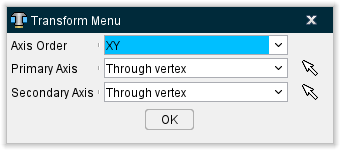
Select Primary/Secondary Axis — This button opens the Transform Menu supplemental window enabling you to set axis priority.
-
Axis Order — Allows you to specify which axes to give priority. Options include XY, YZ, and ZX.
-
Primary Axis and Secondary Axis — These enable you to select the vector where the axes will begin from. Use the dropdown menu to select the feature that will form the basis for the axis and then click the mouse pick icon
 . Once the mouse pick icon is active, you can then click where you choose on the model in the Graphics Area to set the CSYS to that feature.
 -
OK — Saves your selections and closes the window, returning you to the main Transform Menu window.
-
Reset — Undoes any changes made and closes the window.
-
Apply — Saves the changes made.
Reset — Deletes the created Transform menu.
For more information on how to use the Transform menu, see the Using the Transform Menu section at the bottom of this page.
Configure Component menu, Rotate tab
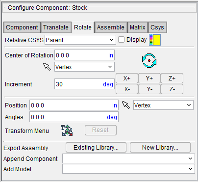
The features on the Rotate tab enable you to rotate the selected object about a rotation center point. Movement occurs each time you press one of the rotation direction buttons: X+/X-, Y+/Y-, Z+/Z-. If the applied movement is incorrect, press the Undo icon in the Project Tree Top Icon Bar to return the object to its previous location.
Relative CSYS — Use this pulldown menu to select which CSYS to use. Options include: Local, Parent, Machine Origin, Active CSYS, and Program_zero. You can toggle on (check) the adjoining Display checkbox to have the CSYS appear in the Graphics Area. The Color Palette icon  next to that checkbox can be used to change the color of the displayed CSYS.
Center of Rotation — Enables you to specify XYZ point location about which to rotate the object. Rotation will always be relative to the active coordinate system. XYZ values can be entered (separated by spaces), or selected by clicking in the field then clicking a position on a model. Press  to see the center of rotation. To remove the center of rotation symbol press the button again, or close the window. You can also use feature based selection to specify the center of rotation. See From/To on the Translate tab for additional information.
Increment — Specifies incremental degrees of rotation to apply when one of the rotation direction buttons are pressed.
Rotation direction buttons — (X+/X-, Y+/Y-, Z+/Z-) When pressed, applies the incremental rotation specified in the Increment field. Rotation occurs about the Center of Rotation, relative to the machine origin.
The remaining features on the Rotate tab, referred to as "location features", are common to all of the following Configure Component menu tabs (Translate, Rotate, Assemble, Matrix, and Csys). They are described in the Configure Component menu, Translate tab section.
Configure Component menu, Assemble tab
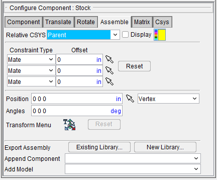
The features on the Assemble tab enable you to move the selected object by assembling (mating or aligning) it with other objects. Objects are assembled by mating or aligning one to three planar surfaces with surfaces on other models. If a non-planar surface is selected, Vericut constructs a tangent plane at the pick point. The relationship of surfaces being mated or aligned is known as a "constraint". If the applied movement is incorrect, press the Undo icon in the Project Tree Top Icon Bar to return the object to its previous location.
Relative CSYS — Use this pulldown menu to select which CSYS to use. Options include: Local, Parent, Machine Origin, Active CSYS, and Program_zero. You can toggle on (check) the adjoining Display checkbox to have the CSYS appear in the Graphics Area. The Color Palette icon  next to that checkbox can be used to change the color of the displayed CSYS.
Constraint Type — Specifies how to constrain selected surfaces during object movement. The following is a list of Constraint Type options:
-
Mate — Moves the object so the selected surface opposes the surface selected on the second object (surface normals oppose each other).
-
Align — Moves the object so the selected surface is aligned with the surface selected on the second object (surface normals point in the same direction).
-
Align Cylinder — This feature can be used to align a component, or model, by the axis of a cylinder. The cylinder can be an STL model (if well defined) or a cut model. The cylinder surface can be either an inner surface (hole) or an outer surface (pin).
Follow the prompts in the logger to pick a common plane and two cylinders to align. Note that plane orientation must be same as the cylinder axis.
When second constraint is also Align Cylinder the component or model is rotated about satisfied constraint to achieve closest position of new constraint. The second constraint cannot be satisfied if the distances between holes or pins are different.
Offset — Use to specify a distance and direction (+ or -) in which to offset the constrained surfaces. The offset is applied normal to the surface.
Reset — Use to reset constraints to receive new data.
Follow these general steps to define a constraint for assembly:
-
For each constraint, click on
 , and then select the desired Constraint Type (Mate or Align) from the pull-down list.
 -
Specify an offset for the constraint if desired.
- Click on
 to put the constraint in pick mode so that you can select the surfaces to be constrained. The arrow will become highlighted as shown in the above picture for the second constraint.
 - In the graphics area, select a surface on the object to be moved.
- In the graphics area, select the surface to move the object relative to.
- After selecting the two surfaces to define a constraint, Vericut moves the object and indicates the satisfied constraint with a checkmark as shown in the picture above for the first constraint.
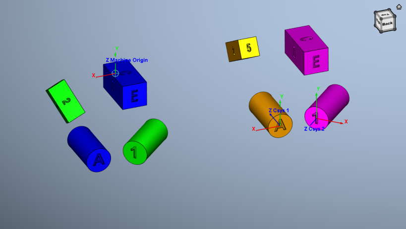
Consider the starting condition below for the examples that follow.
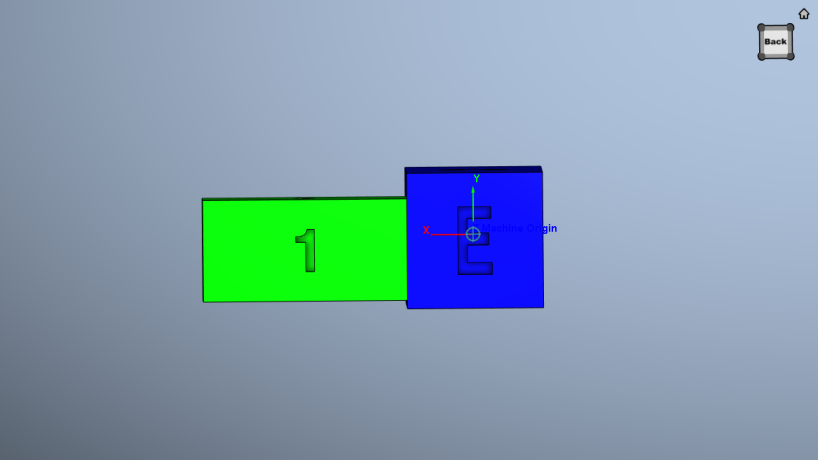
Mated surfaces — the right side of the green model is mated with the left side of the blue model.
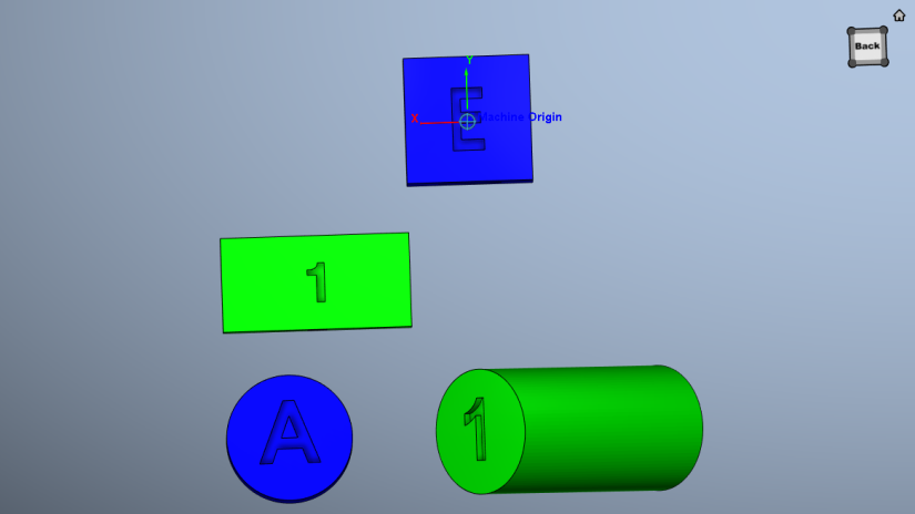
Aligned surfaces — the green block is aligned with the blue block.
The remaining features on the Assemble tab, referred to as "location features", are common to all of the following Configure Component menu tabs (Translate, Rotate, Assemble, Matrix, and Csys). They are described in the Configure Component menu, Translate tab section.
Configure Component menu, Matrix tab
The features on the Matrix tab enable you to move the selected object via a twelve parameter transformation matrix. If the applied movement is incorrect, press the Undo icon in the Project Tree Top Icon Bar to return the object to its previous location.
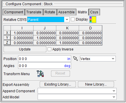
Relative CSYS — Use this pulldown menu to select which CSYS to use. Options include: Local, Parent, Machine Origin, Active CSYS, and Program_zero. You can toggle on (check) the adjoining Display checkbox to have the CSYS appear in the Graphics Area. The Color Palette icon  next to that checkbox can be used to change the color of the displayed CSYS.
Matrix table — The transformation matrix table is similar to the matrix used in programming APT NC programs. Its twelve parameters reveal the geometric attributes of the local (transformed) coordinate system (CSYS) in terms of the machine origin.
The format of the matrix table is as follows:
| I | J | K | D | |
|---|---|---|---|---|
| X | I1 | J1 | K1 | D1 |
| Y | I2 | J2 | K2 | D2 |
| Z | I3 | J3 | K3 | D3 |
Each row represents an axis of the local CSYS. The first three columns represent the vector associated with each axis: I1, J1, K1 as the positive X-axis vector; I2, J2,K2 as the positive Y-axis vector; and I3, J3, K3 as the positive Z-axis vector. The fourth column values D1, D2, D3 represent the coordinates of the origin point of the local CSYS.
📝 NOTE: If you prefer to see the Matrix Table displayed with the I, J, K along the vertical axis and the X, Y, Z along the horizontal axis, set the environment variable, CGTECH_MATRIX_FORMAT=VERTICAL.
Update — Updates the object location to reflect the matrix table transformation. After updating, press OK or Apply to move the object.
Apply Inverse — When selected, inverts the matrix so that its twelve parameters reveal the geometrical attributes of the machine origin in terms of the local (transformed) coordinate system.
The remaining features on the Matrix tab, referred to as "location features", are common to all of the following Configure Component menu tabs (Translate, Rotate, Assemble, Matrix, and Csys). They are described in the Configure Component menu, Translate tab section.
Configure Component menu, Csys tab
The features on the Csys tab enable you to translate the selected object from one coordinate system (CSYS) to another. Select the "From" CSYS and the "To" CSYS to move the object. Movement occurs each time you press the Move button. If the applied movement is incorrect, press the Undo icon in the Project Tree Top Icon Bar to return the object to its previous location.
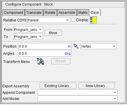
From / To — Specifies the coordinate system to move the object from, and to. Select the appropriate CSYS from each of the pull-down lists.
Move — Moves the selected object from the "From" CSYS to the "To" CSYS orientation.
The remaining features on the Csys tab, referred to as "location features", are common to all of the following Configure Component menu tabs (Translate, Rotate, Assemble, Matrix, and Csys). They are described in the Configure Component menu, Translate tab section.
Using the Transform Menu
Use the Transform Menu to move a CSYS
In the Project Tree, select ![]() Coordinate Systems then Configure Coordinate Systems > Add New CSYS.
Coordinate Systems then Configure Coordinate Systems > Add New CSYS.
A new CSYS named Csys3 is added.
Select ![]() Transform Menu.
Transform Menu.
![]()
📝 NOTE: The Transform Menu allows users to change the position and angles of certain objects in a setup, including machine parts, tools, stocks, and Csys’s. It is able to be used in machine setups, the Assembly Manager, The Tool Manager, and the Tool Change Lists dialog. For full
![]()
Snap the CSYS Origin to a 3D object
📝 NOTE: You can snap the object to another 3D object’s center faces, center edges, and corners by hovering the mouse over the transform CSYS Origin, then clicking and dragging. As you drag the transform CSYS above 3D objects, you will notice it try to snap to them. You can release the mouse button to apply the snap.
![]()
Play with the Snap CSYS Origin feature by selecting different locations in order to become more familiar with this feature.
CSYS Translation along a Single Axis
Toggle on (checked) Enable Translation Increment and set a value, then over your mouse over 1 of the 3 Transform CSYS arrows. You should see the arrow outline highlight light-blue, indicating you can click on it. Click and hold the left mouse button, and drag your mouse to move the object along the axis.
![]()
Play with the CSYS Translation along a Single Axis feature by selecting different locations in order to become more familiar with this feature.
CSYS Translation along Two Axes
To translate along two axes, hover the mouse over one of the small planes that surround the transform CSYS origin. Once one of them is highlighted, you can click and drag to move the object along the plane.
This time, you will see two guidelines, and two numbers show up to the top-right of the Csys. One for one axis, and another for the other axis, color coded to the axes. Translation incrementing also applies here, and you will see cross sections appear along both axis guidelines.
Play with the CSYS Translation along Two Axes feature by selecting different locations in order to become more familiar with this feature.
![]()
CSYS Rotation along Axis
Toggle on (checked) Enable Translation Increment and set a value.
You can rotate along a single axis by hovering the mouse over a ring to highlight it, then click and drag around the origin to rotate. You will notice a black guide ring appear around the origin showing the direction of rotation.
A number in black font to the top-right of the CSYS shows the angle in degrees of how much the object is being rotated.
Once you release the left mouse button, the rotation will be applied. You will notice that the direction of the axes have changed. This is normal. This is to allow the user to translate in defined directions. It also represents how the object will appear if it is a regular CSYS being transformed.
You can also apply rotations in the ‘Rotate’ number box. Just like the ‘Translate’ number box, the order of axes is X Y Z. For example, 0 0 30 would rotate the object by 30 degrees on the Z axis. This ignores incrementing.
![]()
Play with the CSYS Rotation along Axis feature by selecting different locations in order to become more familiar with this feature.