Configure Coordinate System branch menu
Location:
Project Tree > Coordinate System branch (Configure “on”)
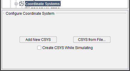
The features on the Configure Coordinate System branch menu enable you to add a new coordinate system (CSYS) to a Coordinate System branch. All of the following features are also available on the Configure Coordinate System menu and are described in detail in the next section.
Configure Coordinate System menu
Location:
Project Tree > Coordinate System (Configure “on”)
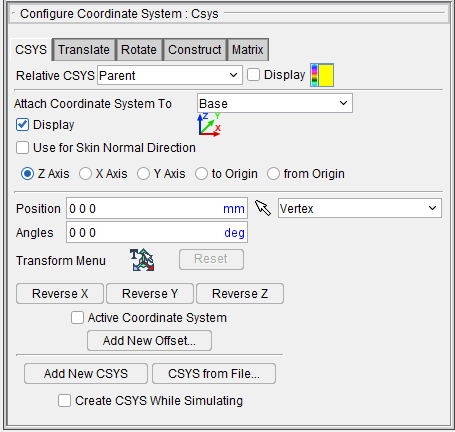
The Configure Coordinate System menu enables you to define, or modify a coordinate system, also known as a "CSYS". It also enables you to specify the "active" coordinate system.
To see axis representing the "active" CSYS in the Vericut graphics area, select Project tab > Axes and toggle Display Active Coord. Sys. "on" (checked).
A user-defined CSYS is typically used to locate an APT or CLS NC program for proper relationship to the workpiece. You can also use a user-defined CSYS for defining section planes, or for gathering measurement data.
📝 NOTES:
-
Defining a CSYS is not recommended for locating G-Code NC programs simulated on a 3-D machine, as this can cause the workpiece to move in the machine view. Instead, use an Input Program Zero table, or Work Offsets/Shift Offsets table if work offsets or shift offsets are present in the NC program file.
-
Vericut can also be configured to process the following APT-CLS NC program records to set the NC program CSYS: CATIA0, MSYS.
CSYS tab —Features on the CSYS tab enable you to attach the selected coordinate system to a component, designate that the coordinate system be used for cut stock transition, and override “global” coordinate system visibility and colors for the coordinate system.
Translate tab — Features on the Translate tab enable you to translate the selected CSYS via indicating "from" and "to" points to move the CSYS. Movement occurs each time you press the Move button.
Rotate tab — Features on the Rotate tab enable you to rotate the selected CSYS about a rotation center point.
Construct tab — Features on the Construct tab enable you to construct a CSYS via a point representing the CSYS origin, and two direction vectors representing the axes of the CSYS. Each can be defined using points, planes and vectors.
Matrix tab — Features on the Matrix tab enable you to move the selected CSYS via a twelve parameter transformation matrix.
Relative CSYS — Use this pulldown menu to select which CSYS to use. Options include Local, Parent, Machine Origin, Active CSYS, and Program_zero. You can toggle on (check) the adjoining Display checkbox to have the CSYS appear in the Graphics Area. The Color Palette icon  next to that checkbox can be used to change the color of the displayed CSYS.
Location features
The Location features are common to all Configure Coordinate System menu tabs and show the selected coordinate system's position and angle, reverse the direction of a specific axis, and specify the active coordinate system. Values shown are relative to the workpiece origin. If the applied movement is incorrect, press the Undo icon in the Project Tree Top Icon Bar to return the object to its previous location.
Position — Specifies the absolute XYZ position of the CSYS, separated by spaces.
Angles — Specifies the absolute XYZ rotation of the CSYS, separated by spaces.
Reverse X — Reverses the X axis of the "active" coordinate system. (See note below)
Reverse Y — Reverses the Y axis of the "active" coordinate system. (See note below)
Reverse Z — Reverses the Z axis of the "active" coordinate system. (See note below)
📝 NOTE: In order to maintain a right handed csys, the following will occur when an axis is reversed:
-
If the X axis is reversed, then the Z axis is also reversed.
-
If the Y axis is reversed, then the X axis is also reversed.
-
If the Z axis is reversed, then the Y axis is also reversed.
Transform menu — Use the ![]() icon to open the Transform Menu window, enabling you to create a transform menu.
icon to open the Transform Menu window, enabling you to create a transform menu.
![]()
Once the Transform Menu window is open, a new kind of CSYS will appear in the Graphics Area. This axis can be used to manually manipulate the CSYS from the Graphics Area.
![]()
The axis arrows translate the object along the selected axis. A guideline will appear showing you the axis that will be traveled.
The outer rings rotate the object around the central axis. A rotational circle will appear showing you how the object will rotate.
The inner planes translate the object along two adjacent axes. Two guidelines will appear showing you the axes that will be traveled.
The origin snaps the object to the center points, edges, and corners of other objects in the scene.
-
Translate — Use this field to manually enter the XYZ units you want the CSYS to move by.
-
Rotate — Use this field to manually enter the XYZ degrees you want the CSYS to rotate by.
-
Enable Translation Increment — Toggle this feature on (checked) to specify positional movements down to the decimal point. The adjoining dropdown menu will then become active and you can manually enter the number of decimal points or use the arrow bars to increase or decrease the numbers by 0.1.
-
Enable Rotation Increment — Toggle this feature on (checked) to specify degree rotations down to the decimal point. The adjoining dropdown menu will then become active and you can manually enter the number of decimal points or use the arrow bars to increase or decrease the numbers by 0.1.
-
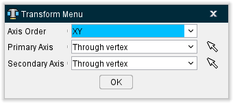
Select Primary/Secondary Axis — This button opens the Transform Menu supplemental window enabling you to set axis priority.
-
Axis Order — Allows you to specify which axes to give priority. Options include XY, YZ, and ZX.
-
Primary Axis and Secondary Axis — These enable you to select the vector where the axes will begin from. Use the dropdown menu to select the feature that will form the basis for the axis and then click the mouse pick icon
 . Once the mouse pick icon is active, you can then click where you choose on the model in the Graphics Area to set the CSYS to that feature.
 -
OK — Saves your selections and closes the window, returning you to the main Transform Menu window.
-
Reset — Undoes any changes made and closes the window.
-
Apply — Saves the changes made.
Reset — Undoes any changes made in the Transform Menu.
Reverse X — Use to invert the CSYS along the X axis.
Reverse Y — Use to invert the CSYS along the Y axis.
Reverse Z — Use to invert the CSYS along the Z axis.
Active Coordinate System — Toggle "on" (checked) the Active Coordinate System feature to designate the coordinate system currently highlighted in the Project Tree to be the "active" coordinate system. See Active Coordinate System for additional information.
📝 NOTE: This feature is not applicable to the Tool Manager, Configure Coordinate Systems menu.
Add New Offset — Opens Configure G-Code Offsets menu, enabling you to designate G-Code Offsets.
The following features are available on all Configure Coordinate system menu tabs and also on the Configure Coordinate System branch menu.
Add New CSYS — Generates a CSYS to edit in the Project Tree.
Project Tree, Configure Coordinate System menu — When accessed in the Project Tree, Configure Coordinate Systems menu, adds a new CSYS to the Coordinate Systems branch in the Project Tree. Vericut automatically provides a unique name for the CSYS. You can right-click on the default name and select Rename from the menu that displays to rename the CSYS if desired.
New coordinate systems are created with zero translation and rotation values and attached to the Base component. The newly added coordinate system is automatically selected in the Project Tree. Use the Configure Coordinate System menu to make any necessary modifications to the newly added CSYS.
If Add New CSYS was pressed in the Configure Coordinate System branch menu, the Configure Coordinate System menu automatically displays enabling you to make any necessary modifications to the newly added CSYS.
Tool Manager, Configure Coordinate System menu — When accessed in the Tool Manager, Configure Coordinate Systems menu, adds a new CSYS to the Coordinate Systems list in Tool Manager. Vericut automatically provides a unique name for the CSYS. You can right-click on the default name and select Rename from the menu that displays to rename the CSYS if desired.
New coordinate systems are created with zero translation and rotation values and attached to the tool origin. The newly added coordinate system is automatically selected in the Coordinate Systems list. Use the Configure Coordinate System menu to make any necessary modifications to the newly added CSYS.
CSYS from File — Displays a file selection box enabling you to specify the CSYS file to be used.
When accessed in the Tool Manager, Configure Coordinate Systems menu, Vericut will read the file and creates CSYS's attached to the selected component.
The Create CSYS While Simulating feature (described below) must be toggled Off when using CSYS from File. This functionality is also available via the csys_file command line option.
See CSYS File in the Getting Started section of Vericut Help for information on CSYS file formats.
When accessed in the Tool Manager, Configure Coordinate Systems menu, Vericut will read the file and create a CSYS attached to the selected tool.
Create CSYS While Simulating — When toggled "on" (the default), coordinate systems are unconditionally created when a matrix statement is encountered in the NC program being simulated. The coordinate systems are attached to the stock's parent (the "attach" component). This feature must be toggled "off" when creating them on your own or using the CSYS from File feature (described above).
📝 NOTE: This feature is not applicable to the Tool Manager, Configure Coordinate Systems menu
Configure Coordinate System menu, CSYS tab
The features on the Csys tab enable you to attach a coordinate system to a component, designate a coordinate system used for cut stock transition, and override "global" coordinate system visibility and colors.
Attach Coordinate System To — Enables you to attach a CSYS to a particular component so that if the component gets repositioned, the CSYS also gets repositioned, maintaining the defined relationship. Select the component from the pull-down list.
📝 NOTE: This feature is not applicable to the Tool Manager, Configure Coordinate Systems menu.
Display — Toggle this feature on (checked) to cause the CSYS to be visible in the Graphics Area.
 (Color Palette) — The Color Palette icon enables you to override the "global" coordinate system to choose the display color for the CSYS. The right side of the Color Palette icon shows the current color for the coordinate system. To change the color for the coordinate system, click on the (Color Palette) icon to display the color palette window shown below.
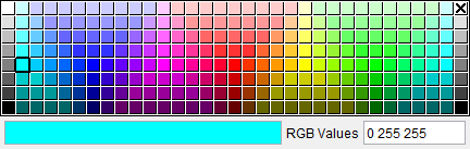
Click on the color in the color palette window, to specify the color for the coordinate system. The color palette window will close and the right side of the (Color Palette) icon in the Configure Coordinate System menu: CSYS tab will update to reflect the selected color.
To close the color palette window without changing the color, click on the  in the upper right corner of the color palette window.
Use for Skin Normal Direction — Toggle on (checked) to guide VDAF using the skin normal direction. Select between Z Axis, X Axis, Y Axis, to Origin, or from Origin to determine which direction will be used.
The remaining features are common to all Configure Coordinate System menu tabs and are described in detail in the Configure Coordinate System menu section.
Configure Coordinate System menu, Translate tab
The features on the Translate tab enable you to translate the selected CSYS via indicating "from" and "to" points to move the CSYS. Movement occurs each time you press the Move button.
![]()
From / To — Use the From and To text fields to specify the "from" point, and the "to" point, to be used for moving the CSYS. XYZ values can be entered (separated by spaces), or selected by clicking in the field then clicking on a model. As you move the mouse over the Vericut model, a crosshair and vector show you the pending pick-point location. Graphical selection supports picking corner points and midpoints of uncut model geometry, or virtually any point on machined features or tool assembly features.
When this menu is accessed from the Project Tree, the From and To points are relative to the workpiece origin.
When accessed from the Tool Manager, the From and To points are relative to the tool origin.
Move — Moves the selected CSYS by the incremental distance, as calculated from the "From" point to the "To" point location.
Back — Moves the selected CSYS by the incremental distance, as calculated from the "To" point to the "From" point location.
Local Translation — When toggled "on", From/To values are relative to the current CSYS.
📝 NOTE: This feature is useful when trying to align a CSYS to the center of a machined hole.
Position CSYS at Component Origin — Enables you to position the origin of the coordinate system currently selected in the Project Tree at the origin of the selected component.
Click on the ![]() icon to enable you to pick a component in the graphics area. Once you have clicked on the icon, the Position field becomes highlighted in yellow and the component origin will display in the graphics area when the mouse pointer is held over a component. Selecting a component in the graphics area sets the Position field to the coordinates of the selected component’s origin and the origin of coordinate system that is selected currently selected in the Project Tree will be repositioned to the coordinates.
icon to enable you to pick a component in the graphics area. Once you have clicked on the icon, the Position field becomes highlighted in yellow and the component origin will display in the graphics area when the mouse pointer is held over a component. Selecting a component in the graphics area sets the Position field to the coordinates of the selected component’s origin and the origin of coordinate system that is selected currently selected in the Project Tree will be repositioned to the coordinates.
📝 NOTE: This feature is not applicable to the Tool Manager, Configure Coordinate Systems menu.
The remaining features are common to all Configure Coordinate System menu tabs and are described in detail in the Configure Coordinate System menu section.
Configure Coordinate System menu, Rotate tab
The features on the Rotate tab enable you to rotate the selected CSYS about a rotation center point. Movement occurs each time you press one of the rotation direction buttons: X+/X-, Y+/Y-, Z+/Z-.
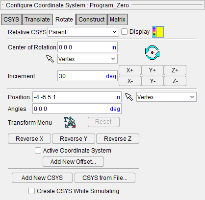
Center of Rotation — Specifies XYZ point location about which to rotate the CSYS. XYZ values can be entered (separated by spaces), or selected by clicking in the field then clicking on a model. To see the center of rotation, press  . To remove the center of rotation symbol press the button again, or close the Coordinate System window.
Increment — Specifies incremental degrees of rotation to apply when one of the rotation direction buttons are pressed.
Rotation direction buttons — (X+/X-, Y+/Y-, +/Z-) When pressed, applies the incremental rotation specified in the Increment field. Rotation occurs about the Center of Rotation, relative to the Attach Component's CSYS.
Local Rotation — When toggled "on", the incremental rotation values are relative to the current CSYS.
📝 NOTE: This feature is useful when trying to align a CSYS to the center of a machined hole.
The remaining features are common to all Configure Coordinate System menu tabs and are described in detail in the Configure Coordinate System menu section.
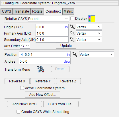
Configure Coordinate System menu, Construct tab
The features on the Construct tab enable you to construct a CSYS via a point representing the CSYS origin, and two direction vectors representing the axes of the CSYS. Each can be defined using points, planes and vectors.
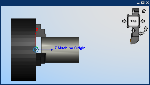
While the Construct tab is active, a marker is displayed in the graphics area (see the picture below) showing the current position/orientation of the axis being constructed based on the Construct tab settings. The display is updated each time you change a value on the Construct tab. The marker is automatically clears when you leave the Construct tab.
Origin (XYZ) — Use these features to define a point representing the origin of the CSYS.
Primary Axis (IJK) — Use these features to define a point or vector representing the direction of the CSYS primary axis.
Secondary Axis (IJK) — Use these features to define a point or vector representing the direction of the CSYS secondary axis.
For each of the items above, you can either enter the coordinates of the point, separated by spaces, in the text field or select one of the construction methods and pick geometry in the graphics area to define the item. Choose one of the construction methods from the pull-down list, then click the arrow ![]() and follow the prompts in the message area to define the item. The following construction methods are available:
and follow the prompts in the message area to define the item. The following construction methods are available:
Point — Use to select a point.
Vector/Plane — Define a point represented by the intersection of a vector with a plane.
3 Planes — Define a point represented by the intersection of three planes.
Circle — Define a point represented by the center of a circle.
-
Choose Circle from the pull-down list, and then click the arrow
 to enable selecting geometry in the graphics area.
 -
Follow the prompts in the temporary message area above the Vericut Logger panel to define the circle center point.
- Pick the XY plane of the circle.
- Pick the cylinder/cone face that contains the circle.
- The circle center point will display in the graphics area and the coordinates of the center point will display in the text field of the entity that you are currently describing on the Construct tab.
CSYS Origin — Define a point represented by the origin of an existing coordinate system.
📝 NOTE: When using one of the point construction methods to define the Primary or Secondary Axis, the origin is subtracted from the generated point to define the direction vector representing the axis.
Vector — Define the direction of a CSYS axis by selecting a vector. (not available for Origin)
Plane/Plane — Define the direction of a CSYS axis by a vector represented by the intersection of two planes. (not available for Origin)
Axis Order — Choose from the pull-down list to assign X, Y or Z to the Primary and Secondary axes of the CSYS.
XY — assigns the Primary Axis to be X and the Secondary Axis to be Y.
YZ — assigns the Primary Axis to be Y and the Secondary Axis to be Z.
ZX — assigns the Primary Axis to be Z and the Secondary Axis to be X.
Update — Use the values selected above to update an existing CSYS, or create a new CSYS. When the Update button is pressed the following occurs:
-
The Primary Axis and the Secondary Axis are crossed to determine the third axis.
-
The third axis is then crossed with the Primary Axis to ensure that the Secondary Axis is orthogonal.
- The CSYS currently active in the Coordinate System window is updated with the resultant orthogonal coordinate system and the origin. If no CSYS is currently active, Vericut creates a new CSYS and automatically assigns it a unique name.
The remaining features are common to all Configure Coordinate System menu tabs and are described in detail in the Configure Coordinate System menu section.
Configure Coordinate System menu, Matrix tab
The features on the Matrix tab enable you to move the selected CSYS via a twelve parameter transformation matrix.
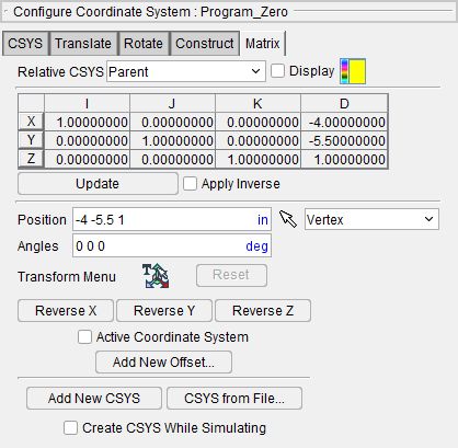
Matrix Table — The transformation matrix table is similar to the matrix used in programming APT tool paths. Its twelve parameters reveal the geometrical attributes of the local (transformed) coordinate system (CSYS) in terms of the workpiece origin.
The format of the matrix table is as follows:
| I | J | K | D | |
|---|---|---|---|---|
| X | I1 | J1 | K1 | D1 |
| Y | I2 | J2 | K2 | D2 |
| Z | I3 | J3 | K3 | D3 |
Each row represents an axis of the local CSYS. The first three columns represent the vector associated with each axis: I1, J1, K1 as the positive X-axis vector; I2, J2,K2 as the positive Y-axis vector; and I3, J3, K3 as the positive Z-axis vector. The fourth column values D1, D2, D3 represent the coordinates of the origin point of the local CSYS.
📝 NOTE: If you prefer to see the Matrix Table displayed with the I, J, K along the vertical axis and the X, Y, Z along the horizontal axis, set the environment variable, CGTECH_MATRIX_FORMAT=VERTICAL.
Update — Updates the CSYS location to reflect the matrix table transformation.
Apply Inverse On Update — When selected, inverts the matrix so that its twelve parameters reveal the geometrical attributes of the workpiece origin in terms of the local (transformed) coordinate system.
The remaining features are common to all Configure Coordinate System menu tabs and are described in detail in the Configure Coordinate System menu section.