Configure Design Locations menu
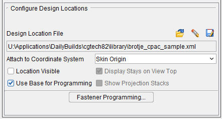
Design Locations File — A Design Locations File is used by AUTO-DIFF to compare data collected during simulation with the design location data in the Design Locations File. Use the following features to open, remove, or save, an existing Design Locations file.
![]() (Open File) — Displays the "Open a fastener locations file" file selection window enabling you to specify the /path/filename of the Design Locations file to be used.
(Open File) — Displays the "Open a fastener locations file" file selection window enabling you to specify the /path/filename of the Design Locations file to be used.
![]() (Remove Design) — Enables you to remove the Design Location file from the Project file.
(Remove Design) — Enables you to remove the Design Location file from the Project file.
![]() (Save File) — Displays the "Save a fastener locations file" file selection window enabling you to specify the /path/filename of the location where the Design Locations file is to be saved.
(Save File) — Displays the "Save a fastener locations file" file selection window enabling you to specify the /path/filename of the location where the Design Locations file is to be saved.
Attach to Coordinate System — Use to specify the coordinate system that the Design Locations data is to be attached to. Select the coordinate system from the pull-down list.
Location Visible — Use to turn the display of the Design Locations data "on" (checked) and "off" in the graphics area.
Use Base for Programming — Causes VDAF to look at materials in both directions of a projection. Toggle on (checked) to enable functionality.
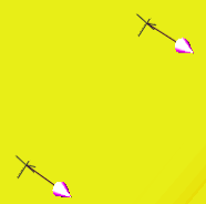
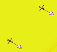
Display Stays on View Top — When toggled on (checked) the Design Locations markers are always drawn on top of the view regardless their 3D z depth.
| Display Stays on View Top“off” | Display Stays on View Top“on” |
|---|---|
 |
 |
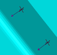
| View “Reversed” | View “Reversed” |
 |
 |
Show Projection Stacks — When toggled on (checked), projection stacks are displayed.
| Display Stays on View Top = “off” Show Projection Stacks = “on” |
Display Stays on View Top = “on” Show Projection Stacks = “on” |
|---|---|
 |
 |
| View “Reversed” | View “Reversed” |
|
 |
Fastener Programming — Starts the Vericut Fastener Programming application enabling you to create a Design Locations file. See Vericut Drill and Fastener Programming Help for more information.