Configure Fastener Models menu
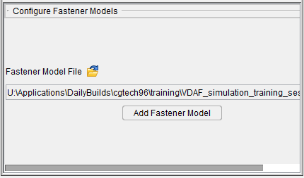
Fastener Model File — This button opens the Open window for Fastener Models, enabling you to load a preexisting fastener model file.
Add Fastener Model — Displays the Configure Fastener Model menu at the bottom of the Project Tree. The Configure icon at the top of the Project Tree must be toggled "on".
Configure Fastener Model menu
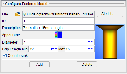
File — Use this feature to specify an existing Fastener Model file. Click on the ![]() (Open File) icon to display the Open ... file selection window and use its features to specify the /path/filename of the Fastener Model file.
(Open File) icon to display the Open ... file selection window and use its features to specify the /path/filename of the Fastener Model file.
Sketcher — Selecting Sketcher opens the Profile Sketcher window in "solid of revolution" mode.
ID — Use the ID text field to specify an ID for the fastener that you are creating. If an ID is not specified, Vericut will assign a unique default ID.
Description — Use the Description text field to add a description for the fastener.
Appearance — Use this feature to specify a color for the fastener.
The right side of the ![]() (Color Palette)
icon shows the current color for the component. To change the color for the component, click on the
(Color Palette)
icon shows the current color for the component. To change the color for the component, click on the
![]() (Color Palette) icon to display the color palette window shown below.
(Color Palette) icon to display the color palette window shown below.
![]()
Click on a color in the color palette window, to specify the color for the fastener. The color palette will close and the right side of the ![]() (Color Palette) icon in the Configure Fastener Model menu will update to reflect the selected color.
(Color Palette) icon in the Configure Fastener Model menu will update to reflect the selected color.
To close the color palette window without changing the color, click on the ![]() in the upper right corner of the color palette.
in the upper right corner of the color palette.
Diameter — Use the Diameter text field to enter the diameter of the fastener. The Diameter value is compared to the hole diameter to ensure that the fastener is appropriate for the drilled hole.
Grip Length — The grip length values are compared to the total stack thickness at the location where the fastener is to be inserted to ensure that the fastener is appropriate for use at the location. If the Min and Max values are zero, they are ignored.
Min — Use the Min text field to enter the minimum grip length value for the fastener.
Max — Use the Max text field to enter the maximum grip length value for the fastener.
Countersink — Toggle "on" (checked) to indicate that the fastener requires a countersunk hole. The fastener's countersink setting and the hole's countersink setting are compared at each location to ensure that the fastener is compatible with the hole.
Add — Adds the fastener described in the Configure Fastener Model menu to the Project Tree.
Delete — Deletes the highlighted fastener from the Project Tree.
Open window for Fastener Models
The Open file selection window for models enables you to add one or more model files (ref. Vericut File Descriptions in the Getting Started section of Vericut Drill and Fastener Simulation Help for information about supported model types).
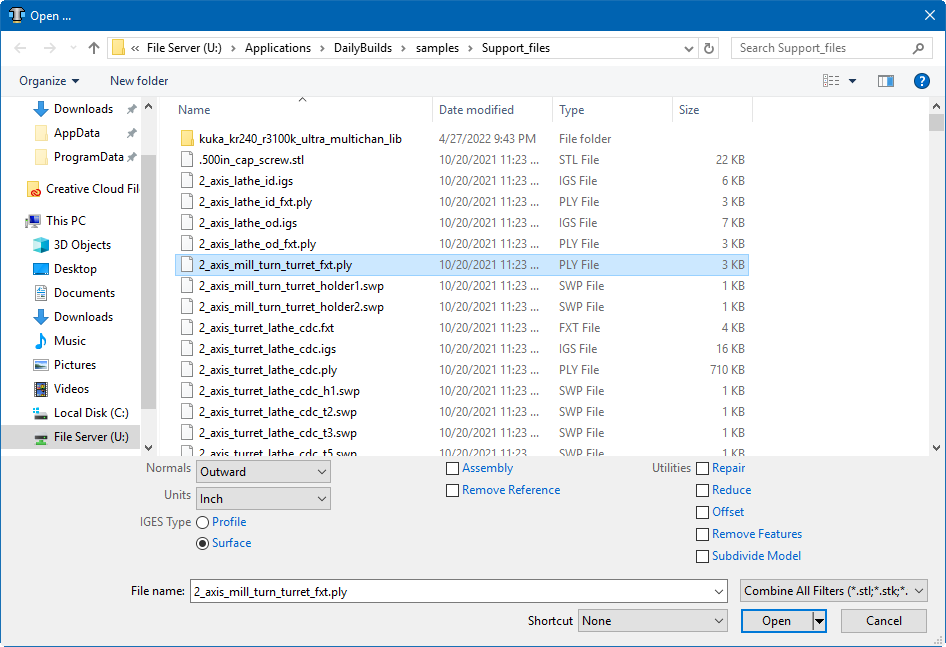
Most features on this window are standard file selection window features that enable you to navigate through directories, filter files, and type, or select, /path/filenames. A description of features specific to Vericut can be found in the Introduction to Vericut File Selection Windows in the Getting Started section of Vericut Drill and Fastener Simulation Help.