Project Tab
The Project tab contains various features related to Project Tree, tools, setups, displays, and various other features. All features will be summarized on this page but each hyperlinked feature can be clicked on to see a more detailed description for more information.
Project group
-
Project Tree — opens the Project Tree panel enabling you to manage all files related to running your Vericut project.
-
Tools — opens the Tool Manager window enabling you to manage your tools.
-
Settings — opens the Settings window enabling you to configure various settings for several features.
-
Variables — opens the Variables panel where you can monitor, initialize, and maintain G-Code variables.
-
Offsets — opens the Offsets panel enabling you to add, modify, and delete G-Code Offsets.
Setup group
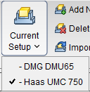
- Current Setup — displays a pulldown list of all available Setups. A check mark is displayed next to the current setup (see below). Clicking on a setup in the list will make it the current one. Inactive setups are displayed in red text.
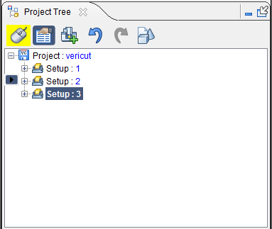
- Add New Setup — appends a new setup after the current setup. The new setup will become the current setup.
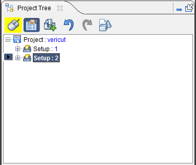 |
Before using Add New Setup, Setup 2 is the “current” setup. |
|---|---|
 |
After using Add Current Setup, Setup 3 is added and becomes the “current” Setup. |
- Delete Current Setup — removes the current setup and makes the next setup in the list the current setup. If the setup at the end of the list is deleted, then the previous setup becomes the current setup. There must always be at least one setup in a project. Therefore, the last remaining setup cannot be deleted.
 |
Before using Delete Current Setup, Setup: 3 is the "current" setup. |
|---|---|
 |
After using Delete Current Setup, Setup: 3 is deleted and Setup: 2 (the next in the list) becomes the "current setup. |
- Import Setup — opens the Import Setup window enabling you to copy a setup from another project and append it after the current setup.
View Controls group
- Axes — opens the View Axes enabling you to control when various axes and coordinate systems are displayed.
-
 Single View Layout — Use to change the layout of View windows to a single window.
 -
 Two View Layout (Horizontal) — Use to change the layout of View windows to two windows arranged side by side.
 -
 Two View Layout (Vertical) — Use to change the layout of View windows to two windows arranged top to bottom.
 -
 Zoom to Box — Use to zoom into a selected area. Select Zoom to Box then left click in a View area and drag the mouse to create a box. The view automatically zooms into that box once the left mouse is released.
 -
 Zoom Box in New View — Use to zoom into a selected area with the selected area becoming a new View window. Functions identically to Zoom to Box.
 -
 View Orthogonal — Snaps the current view to the closest orthogonal view.
 -
 Fit — Use to maximize the view of the stock workpiece. Select an active view then select Fit. The workpiece in the active view will then fill as much of the window as possible while still fitting entirely within the window frame.
 -
 Fit Selected (All Views) — Similar to Fit, above, but applies to all active views.
Utilities group
-
Active Coordinate System — sets the active CSYS that Vericut uses for simulating NC program motions, X-Caliper measurements, and sectioning models. If Display Active Coord. Sys., in the Project tab > View Axes window, is toggled "on" (checked), a coordinate system with the name of the active coordinate system will display in the Vericut graphics area as shown in the picture below. Only the "active" coordinate system will have the marker displayed at its origin as shown in the picture. By default, the active coordinate system will be set at Machine Origin. Use the Configure Coordinate System menu to create additional coordinate systems.
-
MDI — opens the MDI window enabling you to manually enter and process blocks of G-Code data.
- No Animation — turns off all animation. This reduces processing time. No Animation can be toggled on or off while the simulation is running. When No Animation is toggled "on", the graphics display is not updated until either processing is complete or you Stop the processing. At that time the cut model is displayed in it "final" state or the state that it was in when processing was stopped. You can also toggle No Animation On/Off using the No Animation icon in the Vericut toolbar.
Fastener Programming group
-
Fastener Programming — Opens the Fastener Programming panel. See Vericut Drill and Fastener Proramming Help for more information.
-
 (Select all locations) — Selects all drilled hole/fastener locations in the Design Location table and highlights all drilled hole/fastener locations in the graphics area.
 -
 (Undo highlighted changes) — Removes highlighting from all drilled hole/fastener locations in the Design Locations table and deselects all drilled hole/fastener locations in the graphics area.
 -
 (Re-project all sequence locations) — When the Design Locations file is specified on the Design Location card, the fastener locations are projected onto the skin. Use this option to re-project all of the fastener locations for the selected sequence.
 -
 (Use mouse to select or un-select locations by box) — Use to draw a box in the graphics area around the drilled hole/fastener locations you want to select or unselect.
 -
 (Show all locations) — Use to make all design locations visible.
 -
 (Show selected locations) — Use to make all selected design locations visible.
 -
 (Set selected locations as local datums) — Use to set the selected locations as local datums.
 -
 (Set selected locations as global datums) — Use to set the selected locations as global datums.
 -
 (Set selected locations as non-datums) — Use to set the selected locations as non-datums.
 -
 (Fit locations to all views) — Use to “fit” the model to the size of the current view in the graphics area.
 -
 (Run post to generate program) — Use to generate an NC Program for Vericut Drilling and Fastening Programming.