Report Template window
Locations:
- Project Tree > Setup Branch Right Mouse Shortcut Menu > Report > Report Template
- Report tab >
 (Report Template) > Edit
 - Tool Manager > Tool Bar > Report tab > Report Template
Opens the Report Template window enabling you to define a new, or modify an existing, report template. It also enables you to preview the report that will be created, as well as create reports, in HTML or PDF format.
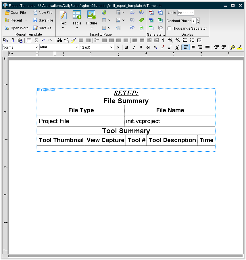
Notice in the picture above that the Report Template window consists of three main areas; the Menu ribbon, the Report Template Content window, and Report Preview window. Each of these areas is describe in detail below.
See the Using Vericut Reports for additional information about using Report Template features and creating Vericut reports.
Report Template Menu ribbon

Menu Ribbon Features
 Open File — Displays a file selection window enabling you to open an existing report template file. The "current" report template file is stored in the Preferences file.
 Recent — Provides a list of recently opened Report Template files. To open a file in the list, select the desired file. The Recent Files List is stored in the Preferences file.
 Open Word — Opens an Open file selection window enabling you to select a Word file to import into the Report Template.
 Save File — Opens a window enabling you to save the current report template file.
 Save As — Opens a window enabling you to save the current report template file under a different name or path.
Add to Page Group

- Text — Use to add text related records to a report template. Select the desired option from the pull-down list. The options in the list will vary depending on where you accessed the Report Template window (Vericut main window, Tool Manager window, or the Inspection Sequence window).
- Date — Adds a record to write out the date with the format selected from the pull-down list.
- Short — "12/24/03"
- Medium — "Dec 24, 2003"
- Long — "December 24, 2003"
- Full — "Wednesday, December 24, 2003"
- Time — Adds a record to write out the time with the format selected from the pull-down list.
- Short — "10:49 AM"
- Medium — "10:49:48 AM"
- Long — "10:49:48 AM PST"
- Page Number — Adds a record to write out page numbers with the format selected from the pull-down list.
- # — "1"
- Page # — "Page 1"
- Page # of # — "Page 1 of 3"
- File Name — Use to add a record to write out the file name. Select the file type from the pull-down list. Choose either, Full Path (to write out the file name in the format /path/filename), or File Name (to write out the file name only), then select the file type from the pull-down list.
- Project File — Adds a record to write out the file name of the "current" Project file.
- Machine File — Adds a record to write out the file name of the "current" Machine file.
- Control File — Adds a record to write out the file name of the "current" Control file.
- Tool Library File — Adds a record to write out the file name of the "current" Tool Library file.
- Design Model File — Adds a record to write out the file name of the "current" Design Model file.
- NC Program — Adds a record to write out the file name of the "current" NC Program File.
- Log File — Adds a record to write out the file name of the "current" Log file.
- Optimized NC Program File — Adds a record to write out the file name of the "current" Optimized Toolpath file.
- Process Data — Adds a record to write out "process" related data of the type selected from the pull-down list.
- Setup Name — Adds a record to write out the name of the Setup.
- Material — Adds a record to write out the "material" specified on the Optimization Control window, Settings tab.
- Machine — Adds a record to write out the "machine" specified on the Optimization Control window, Settings tab.
- Total Time — Adds a record to write out the total time anticipated to machine the part (as simulated by Vericut).
- Total Number of Errors — Adds a record to write out the number of errors detected by Vericut.
- Total Number of Warnings — Adds a record to write out the number of warning detected by Vericut.
- Total Optimized Time — Adds a record to write out the total time anticipated to machine the part (as simulated by Vericut) using optimized toolpath files.
- Total Time Difference — Adds a record to write out the total time difference between Total Time and Total Optimized Time.
- Total Cut Distance % — Adds a record to write out the total percentage of tool movement distance that occurred while in feed rate mode.
- Total Volume Removed — Adds a record to write out the total volume of material removed.
- Stock Envelope — Adds a record to write out the rough dimensions (X, Y, Z) of the stock envelope.
- Stock Envelope X — Adds a record to write out the rough X dimension of the stock envelope.
- Stock Envelope Y — Adds a record to write out the Rough Y dimension of the stock envelope.
- Stock Envelope Z — Adds a record to write out the rough Z dimension of the stock envelope.
- Original Stock Envelope — Adds a record to write out the rough dimensions (X, Y, Z) of the original stock envelope size.
- Original Stock Envelope X — Adds a record to write out the rough X dimension of the original stock envelope size.
- Original Stock Envelope Y — Adds a record to write out the Rough Y dimension of the original stock envelope size.
- Original Stock Envelope Z — Adds a record to write out the rough Z dimension of the original stock envelope size.
- Tool Change Data — Adds a record to write out "tool" related data, of the type selected from the pull-down list, for the current tool.
- Seq — Adds a record to write out the sequential number of the last tool change event.
- Record — Adds a record to write out the last tool change record processed. The record includes both the sequential line number and the record text.
- Tool Description — Adds a record to write out the tool ID and description of a tool retrieved from a Vericut Tool Library file. A blank field indicates a description for this tool was not defined in the library, or the tool did not come from a tool library.
- Cutter Info — Adds a record to write out cutter shape geometry data.
- Cutter Height — Adds a record to write out the height of the cutter.
- Flute Length — Adds a record to write out the flute length of the cutter.
- Gage Point — Adds a record to write out the cutter's gage point value.
- Optimization Record — Adds a record to write out the Optimization tool description and the number of teeth for the tool
- Optimized By — Adds a record to write out the optimization method used for the tool.
- Original Time — Adds a record to write out the anticipated cutting time (as simulated by Vericut) for the tool.
- Optimized Time — Adds a record to write out the anticipated optimized cutting time (as simulated by Vericut) for the tool.
- Time Difference — Adds a record to write out the difference between the optimized and un-optimized cutting times for the tool
- Distance — Adds a record to write out the tool movement distance.
- Distance % — Adds a record to write out the percentage of tool movement distance while in feedrate mode.
- Volume Removed — Adds a record to write out the volume of material removed by the tool.
- Errors — Adds a record to write out the number of errors detected by Vericut for the tool.
- Warnings — Adds a record to write out the number of warnings output by Vericut for the tool.
- Min Extension — Adds a record to write out the minimum height required to avoid shank/holder collisions with the tool.
- Tool ID — Adds a record to write out the Tool ID of the "current" tool.
- Driven Point — Adds a record to write out the driven point of the "current" tool.
- Teeth — Adds a record to write out the number of teeth (flutes) of the "current" tool.
- Cutter ID — Adds a record to write out the Cutter ID of the "current" tool assembly.
- Holder ID — Adds a record to write out the Holder ID of the "current" tool assembly.
- Cutter Diameter — Adds a record to write out the diameter of the "current" tool.
- Cutter Stick-out — Adds a record to write out the "cutter stick-out" value (distance from the tip of the tool to the lowest point on the holder) of the "current" tool.
- Cutter Compensation — Adds a record to write out the cutter compensation value of the "current" tool.
- Comments — Adds a record to adds a blank row enabling you to write comments after the report is created.
- Air Time % — Adds a record to write out the percent of time that the "current" tool spent cutting air.
- Tool Axial Depth — Adds a record to write out the depth of cut.
- Tool Radial Width — Adds a record to write out the width of cut.
- Maximum Spindle Speed — Adds a record to write out the maximum spindle speed.
- Minimum Spindle Speed — Adds a record to write out the minimum spindle speed.
- Maximum Feedrate — Adds a record to write out the maximum feedrate.
- Minimum Feedrate — Adds a record to write out the minimum feedrate.
- Tool Comments — Adds a record to write out the tool's Comments from the tool library.
- Corner Radius — Adds a record to write out the tool's Corner Radius value from the tool library. This feature is only available for inserts and parametric APT cutters.
- Cutter Description — Adds a record to write out the tool's Cutter Description from the tool library.
- Holder Description — Adds a record to write out the tool's Holder Description from the tool library.
- Tool Maximum Spindle Speed — Adds a record to write out the Maximum Spindle Speed value from the tool's Optimization record.
- Tool Minimum Spindle Speed — Adds a record to write out the Minimum Spindle Speed value from the tool's Optimization record.
- Tool Maximum Feedrate — Adds a record to write out the Maximum Feedrate value from the tool's Optimization record.
- Tool Minimum Feedrate — Adds a record to write out the Minimum Feedrate value from the tool's Optimization record.
- Maximum Axial Depth — Adds a record to write out the Maximum Axial Depth value calculated from the NC program for the tool.
- Minimum Axial Depth — Adds a record to write out the Minimum Axial Depth value calculated from the NC program for the tool.
- Maximum Radial Width — Adds a record to write out the Maximum Radial Width value calculated from the NC program for the tool.
- Minimum Radial Width — Adds a record to write out the Minimum Radial Width value calculated from the NC program for the tool.
- Maximum Volume Removal Rate — Adds a record to write out the Maximum Volume Removal Rate value calculated from the NC program for the tool.
- Shank Diameter — Adds a record to write out the diameter of the shank of the tool.
- Sub Program Name — Use to add the Sub Program name file name (No path) for each tool to a Tool Summary table record.
- CGT_REPORT_VAR1-5 — Use to add variables to the Tool Summary table record.
- AUTO-DIFF Data — Adds a record to write out AUTO-DIFF data.
- Gouge Tolerance — Adds a record to write out gouge tolerance.
- Gouge Check Distance — Adds a record to write out gouge check distance.
- Max. Gouge — Adds a record to write out the maximum gouge.
- Line # (Max. Gouge) — Adds a record to write out line number data for maximum gouge.
- Record (Max. Gouge) — Adds a record to write out record data for maximum gouge.
- Tool ID (Max. Gouge) — Adds a record to write out tool ID data for maximum gouge.
- NC Program (Max. Gouge) — Adds a record to write out NC Program data for maximum gouge.
- Min. Gouge — Adds a record to write out minimum gouge.
- Line # (Min. Gouge) — Adds a record to write out line number data for minimum gouge.
- Record (Min. Gouge) — Adds a record to write out record data for minimum gouge.
- Tool ID (Min. Gouge) — Adds a record to write out tool ID data for minimum gouge.
- NC Program (Min. Gouge) — Adds a record to write out NC Program data for minimum gouge.
- Excess Tolerance — Adds a record to write out excess tolerance.
- Excess Check Distance — Adds a record to write out excess check distance.
- Excess Count — Adds a record to write out excess count.
- Max. Excess — Adds a record to write out maximum excess.
- Line # (Max. Excess) — Adds a record to write out line number data for maximum excess.
- Record (Max. Excess) — Adds a record to write out record data for maximum excess.
- Tool ID (Max. Excess) — Adds a record to write out tool ID data for maximum excess.
- NC Program (Max. Excess) — Adds a record to write out NC Program data for maximum excess.
- Min. Excess — Adds a record to write out minimum excess.
- User-Defined Tags — Edit User-Defined Tags — Once one or more user-defined tags have been created, this enables you to add, delete, or modify the tag value.
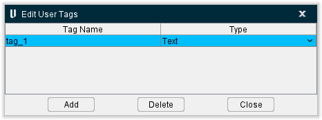
- Add — Adds a new entry to the Edit User-Defined Tags window, enabling you to edit the Tag Name and Type.
- G-Code Variables — Use to write the value of a G-Code Variable to the Vericut Report. Selecting G-Code Variables displays the Variable Name window shown below. Enter the name of the G-Code Variable, whose value that you want to output to the Vericut Report, in the Variable Name text field.
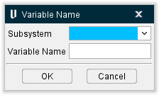
- Subsystem — Select the Subsystem from the pull-down list.
- Variable Name — Use to specify the name of the of the variable whose value you want to output in the Vericut Report.
- OK — Select OK to add a G-Code Variable record to the report template and close the Variable Name window.
- Cancel — Select Cancel to close the Variable Name window without adding a G-Code Variable record to the report template.
📝 NOTES:
-
This feature currently only supports variable types Text and Number (not Array).
-
This feature simply writes out the value of the specified variable to the Vericut report. Use this feature in conjunction within a Custom Table to output a more meaningful entry to the Vericut Report.

- Table — Displays a window enabling you to add a Vericut generated table, or "custom" table, to a report template. Choose one of the following table types from the Table pull-down list. Each type is described in detail in a separate section below.
- Custom Table — Displays the Custom Table window enabling you to output a table of your own design to a Vericut report.
- File Summary Table — Displays the File Summary Table window enabling you to output a Vericut generated file summary table to a Vericut report.
- Tool Summary Table — Displays the Tool Summary Table window enabling you to output a Vericut generated tool summary table to a Vericut report.
- View Capture Table — Displays the View Capture Table window enabling you to output a Vericut generated table containing View Capture images specified using the features on the Project tab > Settings > AutoSave tab: View Capture group.
- Tools Table — Displays the Tools Table window enabling you to output a Vericut generated tool table to tool library report.
- Inspection Features — Displays the Inspection Features Table window enabling you to output a Vericut generated inspection features table to an inspection report.
- Fastener Summary Table — The features in the Fastener Summary Table window enable you to output a Vericut generated fastener summary table to Vericut report.
 Picture — Displays the Picture window enabling you to add Vericut generated pictures, or custom pictures from a file, to a report template.
 Hyperlink — Displays the Hyperlink window you to add a hyperlink to a file, or Web Address, to the report template.
 Page Header — This feature enables you to insert a header into the top of the report.
 Page Footer — This feature enables you to insert a footer into the bottom of the report.
 First Page Header — This feature enables you to insert a specialized header into the top of the first page of the report.
 First Page Footer — This feature enables you to insert a specialized footer into the bottom of the first page of the report.
![]() Page Break — Enables you to manually add page breaks to control printed output.
Page Break — Enables you to manually add page breaks to control printed output.
 NC Program Loop — Use to mark the "start" and "end" of a group of records that will be output for each NC program in project files containing multiple NC programs.
 Tool Change Loop — Use to mark the "start" and "end" of a group of records that will be output at each tool change.
 Inspection Loop — Use to mark the "start" and "end" of a multiple image Setup Plan.
 Setup Plan Loop — Use to mark the "start" and "end" of a group of records that will be output for each Setup Plan in project files containing multiple Setup Plans.
📝 NOTE: Page Break, NC Program Loop, Tool Change Loop, Inspection Loop, and Setup Plan Loop cannot be edited. They can only be deleted.
![]() Edit User-Defined Tags — this enables you to add, delete, or modify user-defined tag values
Edit User-Defined Tags — this enables you to add, delete, or modify user-defined tag values
 Refresh User Tags — Select this feature to ensure that all tags are up to date after changes have been made.
Generate Report group
 (PDF) — Displays the Save Vericut Report file selection window enabling you to specify the /path/filename for the Vericut Report created in PDF format. (The PDF report generation is based in part on iText).
📝 NOTE: The Vericut Report generated from here is different than the one generated from Report tab > Create Report in the Vericut menu ribbon. The report generated from here is based on the Report Template that is currently in memory and is only based on the "current" setup.
 (HTML) — Displays the Save Vericut Report file selection window enabling you to specify the /path/filename for the Vericut Report created in HTML format.
📝 NOTE: The Vericut Report generated from here is different than the one generated from Report tab > Create Report. The report generated from here is based on the Report Template that is currently in memory and is only based on the "current" setup.
 (Text) — Displays the Save Vericut Report file selection window enabling you to specify the /path/filename for the Vericut Report created in Text format.
 (WORD) — Displays the Save Vericut Report file selection window enabling you to specify the /path/filename for the Vericut Report created in Microsoft Word format.
 (CSV) — Displays the Save Vericut Report file selection window enabling you to specify the /path/filename for the Vericut Report created in CSV format.
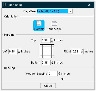
 (Page Setup) — Displays the Page Setup window, enabling you to specify the Report Page Size, Orientation, and Margins.
-
Orientation — Use to select between Portrait and Landscape layouts.
-
Margins — Use to select the relative margins in inches or centimeters.
- Header Spacing — Use to adjust the spacing below the header and spacing between rows of text.
- Line Height — The spacing between lines in percentage of font height. It applies to PDF and HTML. For example, if your font size is 12pt, a 150% line height will add 3pt (25% of 12 pt) above the text and 3pt below the text, making it total row height of 16pt.
Display group
Units — Use this dropdown menu to select whether the ruler is displayed in inches, centimeters, or pixels. Decimal Places — Use this feature to select the number of decimal points that will be displayed for units. Thousands Separator — When toggled on (checked), applies a , or . as specified in your preferences to make numbers more readable.
Report Template Tables
Common Table window Features
The following features are common to all table types except where noted below.
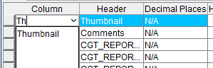
Table Display — Displays records for the selected table. If you type the record type you want into any field of the Column, a list of applicable records that match the phrase you are entering will generate and you can select the record you want from there.
Add — Use to add a record to the table. Select the record that you want the new record added after so that the record becomes highlighted and the press the Add button to add the new record to the table. The new record is added after the highlighted record. If no records are highlighted, the new record is added to the end of the table. You can also add a record by right-clicking in the table and selecting your desired info to add from the menu that generates.
Delete — Use to remove a record from the table. Select the record to be removed so that it becomes highlighted and then press the Delete button. The highlighted record is deleted from the table. You can also delete a table feature by right-clicking on the feature and selecting delete from the menu that generates.
💡 Tips:
- You can also click with the right mouse button in the table to display the following menu and use it to Add/Delete rows.

- You can change the order of the records in the table by clicking on the square button on the left side of the record and while holding the mouse button down, drag the record to the desired location.
Table Width — Use to specify the table width relative to the window/page width. Enter the Table width as a percentage of the window/page width.
Table Alignment — Use to specify whether text will be aligned to the Left, Centered, or aligned to the Right.
Border Size — Use to specify a border size for a "custom" table. Enter the border size in pixels.
Border Color — Use the palette icon to specify the color of the border around each cell.
Image Width — Use to specify the width of "images" included in tables. Toggle "on" (checked) and then enter the width value, in pixels, in the text field.
Image Height — Use to specify the width of "images" included in tables. Toggle "on" (checked) and then enter the width value, in pixels, in the text field.
📝 NOTES: The following rules apply to Thumbnail Width/Thumbnail Height:
-
If only one of the Thumbnail dimensions is toggled "on" (checked), the active dimension will be used and the other direction dimension will be scaled to maintain the image aspect ratio.
-
If neither of the Thumbnail dimensions is toggled "on" (checked), the native image size will be used.
Group Data by Tool — When toggled "on", the Tool Summary Table will group sequences using the same tool. When toggled "off", the Tool Summary Table will list tools sequence by sequence.
📝 NOTE: This feature is only available in the Tool Summary Table window.
Image Background Color — Use the palette icon to specify the background color of the Report Template.
Allow Page Break Inside Table — Toggle this option on (checked) in order to allow table cells to spread across more than one page.
Accent Row Color — Use the palette icon to specify the color of the accent row color.
Close — Closes the Table window without creating a table record in the report template.
See the Using Vericut Reports section of Vericut Help for additional information about using Report Template features and creating Vericut reports.
Custom Table
Custom Tables can be created through Vericut's grid selector.
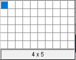
Simply left-click and continue to hold while moving the mouse to select the number of columns and rows you want your Custom Table to have. For instance, if you wanted a Custom Table with 5 columns and 3 rows, you would maneuver the mouse until you had the display shown below. Numbers below the grid selector will also display number of columns x number of rows and will update as you select.

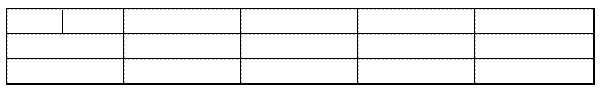
Release the left-mouse button and your desired Custom Table will appear in the Report Template window as shown below.
File Summary Table window
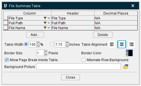
The features in the File Summary Table window enable you to output a Vericut generated file summary table to a Vericut report.
Each row in the File Summary Data List represents a column that will be displayed in a File Summary table in a Vericut Report. The first row in the File Summary Data List is used to define the first column in the File Summary table. The second row in the File Summary Data List defines the second column in the File Summary table.
The order of the rows in the File Summary Data List can be changed by clicking on square button at the beginning of any row and dragging the row to the desired position in the list.
Column — The features in this column are used to specify the type of data that is to be displayed in this column of the report.
-
File Type — Adds the file type (Project File, Machine File, Control File, etc.) to the File Summary table record.
-
Full Path — Adds the entire /file/path including filename to the File Summary table record.
-
File Name — Adds the name of the file to the File Summary table record.
Header — Use to define the column header to be used for the column in the File Summary table. Clicking on the "Header" item in a highlighted row, will put it in edit mode so you can enter a header label that is most meaningful in your work place.
Decimal Places — Use to specify the number of decimal places that numbers will be rounded to if applicable.
The remainder of the window features are common to all table windows and are described in the Common Table Features section.
Tool Summary Table window
The features in the Tool Summary Table window enable you to output a Vericut generated tool summary table to a Vericut report.
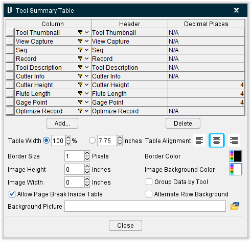
Tool Data List
Each row in the Tool Data List represents a column that will be displayed in the Tool Summary table in a Vericut Report. The first row in the Tool Data List is used to define the first column in the Tool Summary table. The second row in the Tool Data List defines the second column in the Tool Summary table, and so on.
The order of the rows in the Tool Data List can be changed in a couple of ways. Clicking on one of the column headings (Column, Header, Decimal Places) in the Tool Data List will sort the table's rows alphabetically by the items contained in the column. Secondly, you can click on square button at the beginning of any row and drag the row to the desired position in the list.
Column — The features in this column are used to specify the type of data that is to be displayed in this column of the report. Clicking on the "Column" item in a highlighted row, will display a pull-down list of data types that you can select from. The following are the data types that are available for use in a Tool Summary table.
-
Tool Thumbnail — Use to display an image of the tool, in a Tool Summary table record. Turning tool thumbnails are displayed in the XZ plane. All other thumbnails are in ZX plane.
-
View Capture — Use to output an image at the end of each cutting sequence in Tool Summary table record. View Capture, in the Auto Save tab, must have both Cutter Change and File End: End of Each File toggled "on".
-
Seq — Use to add the sequence number of the tool change event, to a Tool Summary table record.
-
Record — Use to add the tool change record processed, to a Tool Summary table record. The record includes both the sequential line number and the record text.
-
Tool Description — Use to add a description of a tool retrieved from a Vericut Tool Library file, to a Tool Summary table record. A blank field indicates a description for this tool was not defined in the library, or the tool did not come from a tool library.
-
Cutter Info — Use to add cutter shape geometry data, to a Tool Summary table record. Includes both the method used to define the cutter shape (shown in square brackets "[ ]", for example [Profile] indicates a profile type of cutter definition) followed by the parameter values used to describe the cutter.
-
Cutter Height — Use to add the height of the cutter to a Tool Summary table record.
-
Flute Length — Use to add the flute length of the cutter to a Tool Summary table record.
-
Gage Point — Use to add the cutter's gage point value to a Tool Summary table record.
-
Optimize Record — Use to add the tool's description and number of teeth to a Tool Summary table.
-
Optimized By — Use to add the optimization method used for the tool to a Tool Summary table record.
-
Original Time — Use to add the anticipated cutting time (as calculated by Vericut) for the tool to a Tool Summary table.
-
Optimized Time — Use to add the anticipated optimized cutting time (as calculated by Vericut) for the tool to the Tool Summary table record.
-
Time Difference — Use to add the difference between the optimized, and un-optimized, cutting times for the tool to a Tool Summary table record.
-
Distance — Use to add the tool movement distance to a Tool summary table.
-
Distance % — Use to add the percentage of the tool movement distance that occurred while in feedrate mode to a Tool Summary table record.
-
Volume Removed — Use to add the volume of material removed by the tool to a Tool Summary table record.
-
Errors — Use to add the number of errors detected by Vericut for the tool to a Tool Summary table record.
-
Warnings — Use to add the number of warnings output by Vericut for the tool to a Tool Summary table record.
-
Min Extension — Use to add the minimum cutter height required to avoid shank/holder collisions with the tool to a Tool Summary table record.
-
Tool ID — Use to add the Tool ID of the tool to a Tool Summary table record.
-
Driven Point — Use to add the driven point of the tool to a Tool Summary table record.
-
Teeth — Use to add the number of teeth (flutes) of the tool to a Tool Summary table record.
-
Cutter ID — Use to add the Cutter ID(s) of the cutter/inserts used in the tool assembly to a Tool Summary record.
-
Holder ID — Use to add the Holder ID(s) of the holders used in the tool assembly to a Tool Summary table record.
-
Cutter Diameter — Use to add the diameter of the tool to a Tool Summary table record.
-
Cutter Stick-out — Use to add the "cutter stick-out" value (distance from the tip of the tool to the lowest point on the holder) of the tool to a Tool Summary table record.
-
Cutter Compensation — Use to add the cutter compensation value of the tool to a Tool Summary table record.
-
Comments — Use to add a blank column enabling you to write comments to a Tool Summary table record after the report is created.
-
Air Time % — Use to add the percent of time that the tool spent cutting air to a Tool Summary table record.
-
Tool Axial Depth — Use to add the Axial Depth value from the Optimize record to a Tool Summary table record.
-
Tool Radial Width — Use to add the Radial Width value from the Optimize record to a Tool Summary table record.
-
Maximum Spindle Speed — Use to add the Maximum Spindle Speed value used in the NC program to a Tool Summary table record.
-
Minimum Spindle Speed — Use to add the Maximum Spindle Speed value used in the NC program to a Tool Summary table record.
-
Maximum Feedrate — Use to add the Maximum Feedrate value used in the NC program to a Tool Summary table record.
-
Minimum Feedrate — Use to add the Minimum Feedrate value used in the NC program to a Tool Summary table record.
-
NC Program — Use to add the NC program file name (No path) for each tool to a Tool Summary table record.
-
Tool Comments — Use to add the tool Comments from the tool library to a Tool Summary table record.
-
Corner Radius — Use to add the Corner Radius value from the tool library to a Tool Summary table record.
-
Cutter Description — Use to add the Cutter Description from the tool library to a Tool Summary table record.
-
Holder Description — Use to add the Holder Description from the tool library to a Tool Summary table record.
-
Tool Maximum Spindle Speed — Use to add the Maximum Spindle Speed value from the tool's Optimize record to a Tool Summary table record.
-
Tool Minimum Spindle Speed — Use to add the Minimum Spindle Speed value from the tool's Optimize record to a Tool Summary table record.
-
Tool Maximum Feedrate — Use to add the Maximum Feedrate value from the tool's Optimize record to a Tool Summary table record.
-
Tool Minimum Feedrate — Use to add the Minimum Feedrate value from the tool's Optimize record to a Tool Summary table record.
-
Tool Maximum Cut Feed — Use to add the Maximum Cut Feed value from the tool's Optimize record to a Tool Summary table record.
-
Maximum Axial Depth — Use to add the Maximum Axial Depth value, calculated from the NC program for the tool, to a Tool Summary table record.
-
Minimum Axial Depth — Use to add the Minimum Axial Depth value, calculated from the NC program for the tool, to a Tool Summary table record.
-
Maximum Radial Width — Use to add the Maximum Radial Width value, calculated from the NC program for the tool, to a Tool Summary table record.
-
Minimum Radial Width — Use to add the Minimum Radial Width value, calculated from the NC program for the tool, to a Tool Summary table record.
-
Maximum Volume Removal Rate — Use to add the Maximum Volume Removal Rate value, calculated from the NC program for the tool, to a Tool Summary table record.
-
Shank Diameter — Use to add the Shank Diameter value from the tool library to a Tool Summary table record.
-
Air Time — Use to add the amount of time that the tool spent cutting air to a Tool Summary table record.
-
Turret – Use to add the Turret number to a Tool Summary table record.
-
MTS ID – Use to add the Multi Tool Station (MTS) ID to the Tool Summary table record.
-
MTS Thumbnail – Use to add thumbnail of the Multi Tool Station (MTS) to the Tool Summary table record.
-
Dimensioned Tool Image – Use to add an image of the dimensioned tool from Tool Manager to the Tool Summary table record.
-
Event ID – Use to add the Event ID from the Tool Change List option to the Tool Summary table record.
-
Sub Program Name – Use to add the Sub Program name file name (No path) for each tool to a Tool Summary table record.
-
CGT_REPORT_VAR1-5 – Use to add variables to the Tool Summary table record.
Header — Use to define the column header to be used for the record in the Tool Summary table. Clicking on the "Header" item in a highlighted row, will put it in edit mode so you can enter a header label that is most meaningful in your work place.
Decimal Places — Specifies number of decimal places that the figures will be rounded to if applicable.
The remainder of the window features are common to all table windows and are described in the Common Table Features section.
View Capture Table window
The features in the View Capture Table window enable you to output a Vericut generated table containing View Capture images, as specified on the Project tab > Settings > AutoSave tab: View Capture group, to a Vericut Report.
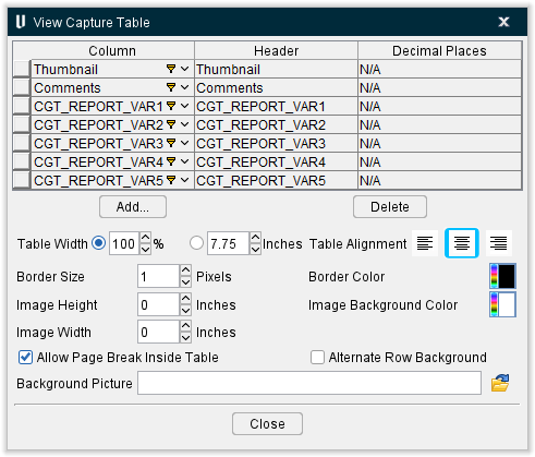
View Capture Data List
Each row in the View Capture Data List represents a column that will be displayed in the View Capture table in a Vericut Report. The first row in the View Capture Data List is used to define the first column in the View Capture table. The second row in the View Capture Data List defines the second column in the View Capture table.
The order of the rows in the View Capture Data List can be changed by clicking on square button at the beginning of any row and dragging the row to the desired position in the list.
Column — The features in this column are used to specify the type of data that is to be displayed in this column of the report.
-
Thumbnail — Displays a View Capture image to a View Capture table record.
-
Comments — Displays Vericut generated comments about the image.
-
CGT_REPORT_VAR1-5 — Displays variables in the View Capture Table.
Header — Use to define the column header to be used for the column in the View Capture table. Clicking on the "Header" item in a highlighted row, will put it in edit mode so you can enter a header label that is most meaningful in your work place.
Decimal Places — Specifies number of decimal places that the figures will be rounded to if applicable.
The remainder of the window features are common to all table windows and are described in the Common Table Features section.
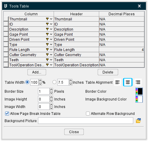
Tools Table window
The features on the Tools Table window enable you to create a tool library report. The Tools Table window is only available when the Report Template window is accessed from the Tool Manager menu ribbon (Project tab > Tools > Report Template).
📝 NOTE: Report templates containing Tools Tables should only be used for creating tool library reports from the Tool Manager window. Using them to create reports from other Vericut applications will result in incorrect data being displayed in the report.
Tool Data List
Each row in the Tool Data List represents a column that will be displayed in the Tool Library Report. The first row in the Tool Data List is used to define the first column in the Tool Library Report. The second row in the Tool Data List defines the second column in the Tool Library Report, and so on.
The order of the rows in the Tool Data List can be changed in a couple of ways. Clicking on one of the column headings (Column, Header, Decimal Places) in the Tool Data List will sort the table's rows alphabetically by the items contained in the column. Secondly, you can click on square button at the beginning of any row and drag the row to the desired position in the list.
-
Column — The features in this column are used to specify the type of data that is to be displayed in this column of the report. Clicking on the "Column" item in a highlighted row, will display a pull-down list of data types that you can select from. The following are the data types that are available for use in a Tool Library Report.
-
Thumbnail — Use to display a thumbnail image of the tool, in a Tool Library Report. Turning tool thumbnails are displayed in the XZ plane. All other thumbnails are in ZX plane.
-
ID — Use to display the alpha-numeric text that identifies the tool in the Tool Library, in a Tool Library Report.
-
Description — Use to display the description of the tool in a Tool Library Report.
-
Gage Point — Use to display the location of the gage point of the tool assembly, in a Tool Library Report.
-
Driven Point — Use to display the offset for the tool control point, or "driven point", in a Tool Library Report.
-
Type — Use to display the type of tool (Mill, Turn, Probe, etc.), in a Tool Library Report.
-
Flute Length — Use to display the tool's flute length in a Tool Library Report.
-
Cutter Geometry — Use to display the cutter geometry (for example, Bull Nose: 1.5, 0.0625, 3.25) in a Tool Library Report.
-
Optimization Description — Use to display the description associated with the tool in a Tool Library Report.
-
Teeth — Use to display the number of teeth that the tool has, in a Tool Library Report.
-
Comments — Use to display any comments from the tool library tool record, in a Tool Library Report.
-
Cutter Compensation — Use to display the cutter compensation value of the tool in a Tool Library Report.
-
Cutter ID — Use to display the ID(s) of the cutter(s) used in the tool assembly, in a Tool Library Report.
-
Holder ID — Use to display the ID(s) of the holder(s) used in the tool assembly, in a Tool Library Report.
-
Cutter Diameter — Use to display the diameter of the cutter in a Tool Library Report.
-
Cutter Height — Use to display the height of the cutter in a Tool Library Report.
-
Cutter Stick-out — Use to display the "cutter stick-out" value (distance from the tip of the tool to the lowest point on the holder) of the tool, in a Tool Library Report.
-
Corner Radius — Use to display the corner radius value of the cutter in a Tool Library Report.
-
Cutter Description — Use to display the Cutter Description in a Tool Library Report.
-
Holder Description — Use to display the Holder Description in a Tool Library Report.
-
Shank Diameter — Use to display the Shank Diameter of the cutter in a Tool Library Report.
-
Tap/Thread Pitch — Use to display the Tap/Thread Pitch of the tap in a Tool Library Report.
See Tool Manager window, also in Vericut Help for additional information on these data types.
-
Dimensioned Tool Image — Use to display sectioned tools with annotated images in a Tool Library Report.
-
Eligible for Coolant Through Types — Displays if CoolantAirThru or CoolantThru macros are enabled.
-
Gage Point X — Use to display the location of the gage point in the X axis of the tool assembly, in a Tool Library Report.
-
Gage Point Y — Use to display the location of the gage point in the Y axis of the tool assembly, in a Tool Library Report.
-
Gage Point Z — Use to display the location of the gage point in the Z axis of the tool assembly, in a Tool Library Report.
Header — Use to define the column header to be used for the record in the Tool Library Report. Clicking on the "Header" item in a highlighted row, will put it in edit mode so you can enter a header label that is most meaningful in your work place.
Decimal Places — Specifies number of decimal places that the figures will be rounded to if applicable.
The remainder of the window features are common to all table windows and are described in the Common Table Features section.
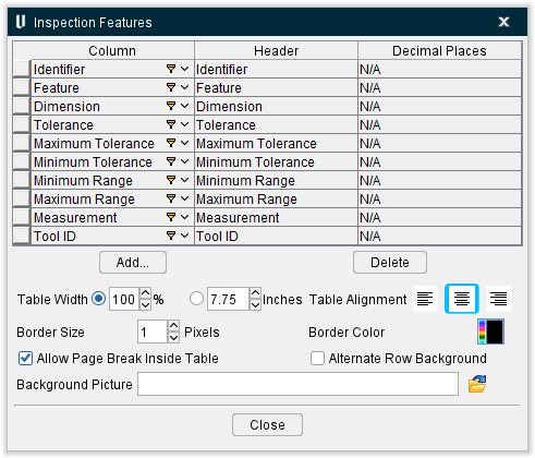
Inspection Features Table window
The features in the Inspection Features Table window enable you to create an inspection report. The Inspection Features Table window is only available when the Report Template window was accessed from the Inspection window menu ribbon (Report tab > Report Template).
📝 NOTE: Report templates containing Inspection Feature Tables should only be used for creating inspection reports from the Inspection window. Using them to create reports from other Vericut applications will result in incorrect data being displayed in the report.
Inspection Feature List
Each row in the Inspection Features List represents a column that will be displayed in the Inspection Report. The first row in the Inspection Features Table is used to define the first column in the Inspection Report. The second row in the Inspection Feature List defines the second column in the Inspection Report, and so on.
The order of the Inspection Feature List's rows can be changed in a couple of ways. Clicking on one of the column headings (Column, Header, Decimal Places) in the Inspection Feature List will sort the table's rows alphabetically by the items contained in the column. Secondly, you can click on square button at the beginning of any row and drag the row to the desired position in the list.
-
Column — The features in this column are used to specify the type of data that is to be displayed in this column of the report. Clicking on the "Column" item in a highlighted row, will display a pull-down list of data types that you can select from. The following are the data types that are available for use in an Inspection Report.
-
Symbol — Use to display the symbol of the type of measurement that the record represents, for example
 for a floor thickness, in an Inspection Report.
 -
Feature — Use to display a very brief description of the type of feature the record represents, for example "Floor Thickness", in an Inspection Report.
-
Identifier — Use to display the feature identifier associated with the inspection record, for example, A1, in an Inspection Report.
-
Instrument — Use to display the type of instrument that is to be used to check the dimension, for example, "Ultrasonic", in an Inspection Report.
-
Dimension — Use to display the expected dimension in an Inspection Report.
-
Tolerance — Use to display the acceptable tolerance value, or range of values, in an Inspection Report.
-
Geo. Tolerance — The geometric tolerance specification associated with the record, for example,
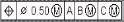 , in an Inspection Report.
 -
Measurement — Use to display the inspector's actual measurement in an Inspection Report.
-
Tool ID — Use to display the identifier of the tool that cut the feature, in an Inspection Report.
See Vericut Inspection, in the Report tab section of Vericut Help for additional information on these data types.
Header — Use to define the column header to be used for the record in the Inspection Report. Clicking on the "Header" item in a highlighted row, will put it in edit mode so you can enter a header label that is most meaningful in your work place.
Decimal Places — Specifies number of decimal places that the figures will be rounded to if applicable.
The remainder of the window features are common to all table windows and are described in the Common Table Features section.
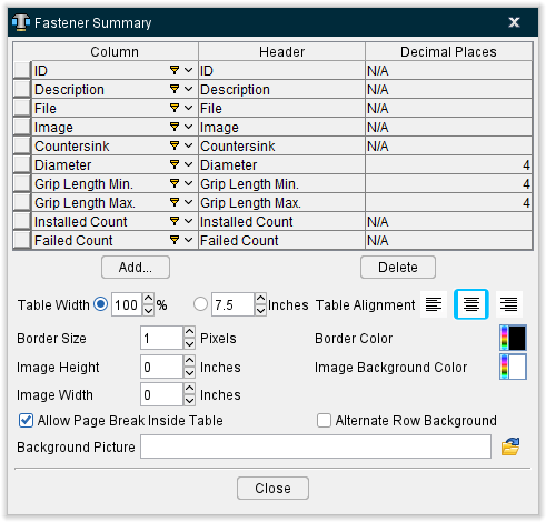
Fastener Summary Table window
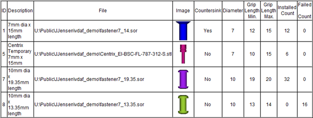
The features in the Table: Fastener Summary Table window enable you to output a Vericut generated Fastener summary table to a Vericut Drill and Fastener report.
Tool Data List
Each row in the Fastener Summary Data List represents a column that will be displayed in the Fastener Summary table in a Vericut Report. The first row in the Fastener Summary Data List is used to define the first column in the Fastener Summary table. The second row in the Fastener Summary Data List defines the second column in the Fastener Summary table, and so on.
The order of the rows in the Fastener Summary Data List can be changed in a couple of ways. Clicking on one of the column headings (Column, Header, Alignment) in the Fastener Summary Data List will sort the table's rows alphabetically by the items contained in the column. Secondly, you can click on square button at the beginning of any row and drag the row to the desired position in the list.
Column — The features in this column are used to specify the type of data that is to be displayed in this column of the report. Clicking on the "Column" item in a highlighted row, will display a pull-down list of data types that you can select from. The following are the data types that are available for use in a Fastener Summary table.
-
ID — Use to add the alpha-numeric text that identifies the fastener to a Fastener Summary table record.
-
Description — Use to add the description of the fastener to a Fastener Summary table record. A blank field indicates a description for this fastener was not defined in the Configure Fastener Model menu.
-
File — Use to add the /path/filename of the Fastener Model file to a Fastener Summary table record.
-
Image — Use to display an image of the fastener to a Fastener Summary table record.
-
Countersink — Use to add the fastener's countersink setting to a Fastener Summary table record.
-
Diameter — Use to add the diameter of the fastener to a Fastener Summary table record.
-
Grip Length Min. — Use to add the minimum grip length value for the fastener to a Fastener Summary table record.
-
Grip Length Max. — Use to add the maximum grip length value for the fastener to a Fastener Summary table record.
-
Installed Count — Use to add the number of fasteners installed during the simulation to a Fastener Summary table record.
-
Failed Count — Use to add the number of fastener installations that failed during the simulation to a Fastener Summary table record.
-
Header — Use to define the column header to be used for the record in the Fastener Summary table. Clicking on the "Header" item in a highlighted row, will put it in edit mode so you can enter a header label that is most meaningful in your work place.
-
Alignment — Left-click in the Alignment cell in a highlighted row and choose Left, Center, or Right from the pull-down list to specify how you want the data in that column of the Fastener Summary table to be positioned.
-
Width % — Use to specify a width for each column based on a percentage of the table width.
-
Decimal Places — Specifies number of decimal places that the figures will be rounded to.
Add — Use to add a row after the highlighted row in the Fastener Summary Data List.
Delete — Use to delete a row after the highlighted row in the Fastener Summary Data List.
💡 Tips:
-
You can also click with the right mouse button in the Inspection Feature List to display the following menu and use it to Add/Delete rows in the Inspection Feature List.

-
You can change the order of the records in the Inspection Feature List by clicking on the square button on the left side of the record and while holding the mouse button down, drag the record to the desired location.
The remainder of the window features are common to all table windows and are described in the Common Table Features section.
Example:
Using a Fastener Summary Table defined as shown in the picture above will result in a table in the Vericut Drill and Fastener Report similar to the following picture.
Picture window
 Picture — Clicking this button will result in a pop-up menu displaying:
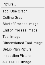
Use this menu to insert your desired image from the pre-selected list. If you want to import an image that is not pre-selected, left-click on Picture... which will then open a file selection window. This will enable you to upload any image you want into the Report. You can also edit the picture by right-clicking on it and selecting Edit Picture... from the right mouse button menu that generates. Doing so will produce the following window:
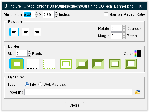
Dimension — Use to specify the width and then the height for the displayed image.
Maintain Aspect Ration — Toggle "on" (checked) this feature to lock the current ratio of width to height so that the values cannot be altered independently.
📝 NOTE: If only one of the dimensions is toggled "on", the active dimension will be used and the other direction dimension will be scaled to maintain the image aspect ratio. If neither of the dimensions is toggled "on", the native image size will be used.
Position Features
-
Position — Use to specify the alignment of the picture: Left, Center, or Right.
-
Rotate — Use to specify how many degrees the picture will be rotated clockwise.
-
Margin — Use to specify how many pixels thick the margin around the picture will be.
Border Features
-
Size — Use to specify the size of the picture's border in pixels.
-
Color — Use the palette icon to specify the color of the picture's border.
-
Border — Use these images to specify the design of the border. Options include: Solid, Dotted, Dashed, Double, Outset, Inset, Grooved, and Ridged.
Hyperlink Features
-
Type — Use to specify the type of hyperlink that you are adding. Select either File or Web Address.
-
Hyperlink — When Hyperlink Type is set to File, enter the full path/ filename of the file you are creating the hyperlink to in the Hyperlink text field, or click on the (Browse) icon to display the Hyperlink file selection window and use it to specify the path/filename.
Close — Closes the Picture window.
Hyperlink window
The features on the Hyperlink window enable you to add a hyperlink to a file, or Web Address, to the report template.
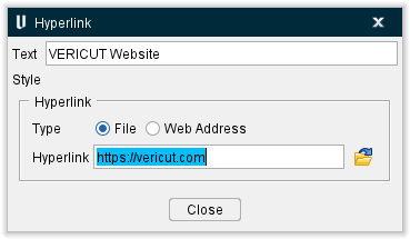
Text — Enter the text that you want displayed for the hyperlink in the text field.
Hyperlink Features
-
Type — Use to specify the type of hyperlink that you are adding. Select either File or Web Address.
-
Hyperlink — When Hyperlink Type is set to File, enter the full /path/filename of the file you are creating the hyperlink to in the Hyperlink text field, or click on the
 (Browse) icon to display the Hyperlink file selection window and use it to specify the path/filename. When Hyperlink Type is set to Web Address, enter the web address (for example, https://vericut.com) in the Hyperlink text field. Vericut will automatically add the "http://" to the web address.
OK — Adds the Hyperlink record to the report template and closes the Hyperlink window.
Cancel — Closes the Hyperlink window without adding a Hyperlink Record to the report template.
Example
Using a Hyperlink window defined as shown in the picture above will result in a hyperlink in the Vericut Report similar to the following picture.