Vericut Views
Introduction to Vericut Views
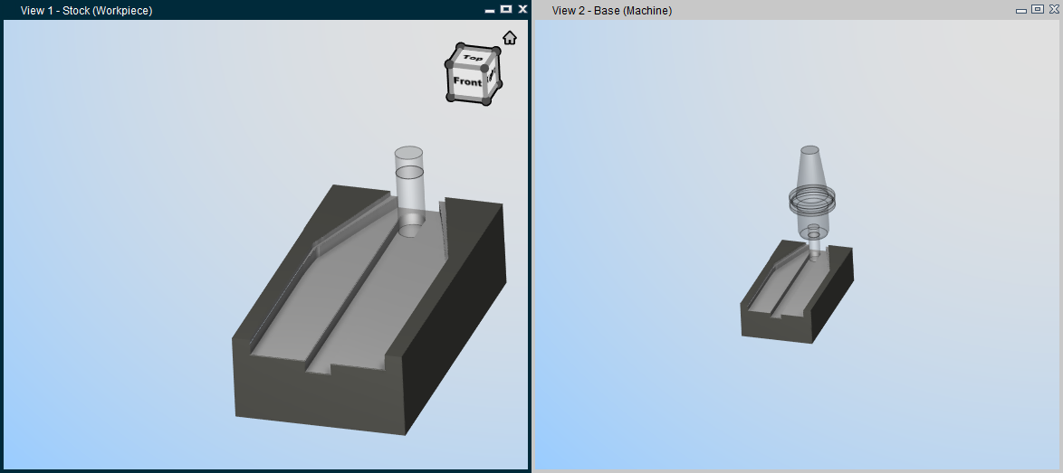
One of the most powerful advantages of Vericut's user interface is flexibility in viewing the simulation. The simulation can be viewed from any distance or direction, in as many views as required to gain good visibility of the machining process. Just a click away, you can change the quantity and layout of view ports, each capable of showing machining on the workpiece, the NC machine, or a "combined" view where machining takes place on the machine.
Orienting views
Objects can be quickly oriented in standard drawing views, dynamically manipulated, and sectioned to "virtually see" every aspect of machining. Vericut provides tools to rotate, zoom, pan, and reverse models in any view. Use the View tab > Orient function or the corresponding Toolbar options to change the view angle or distance. Each view in the Vericut window is independently controlled.
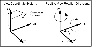
The "View coordinate system"
View rotations are performed about X, Y, or Z axes of a right-hand Cartesian "view coordinate system". The "view coordinate system" is oriented such that the Y-axis is parallel the left edge of the computer screen, the X-axis is parallel to the bottom edge and the Z-axis points out of the screen towards you. By default, the origin of the of the "view coordinate system" is the center of the view in the plane of the screen.
View attributes
View attributes add to visualization power by enabling you to:
-
Change what is seen in a view: workpiece machining, machine motions without machining, or machining a workpiece on a machine.
-
Show machines in shaded or wireframe display.
- Control light direction.
- Change the background, including ability to add walls and a floor in a view of an NC machine.
Each view has its own individually controlled attributes.
See View Orient window and View Attributes window section of Vericut Help.
Also see Configure Coordinate System menu in the Project Tree section of Vericut Help.
Layout group
Using View Layout features
The options in the Layout group control how many views of the Vericut model are seen, and how they are arranged. All views are contained within the Vericut main window. The size and orientation of the model in each view is individually controlled. View port size and layout are saved in the project file.
One view is considered by Vericut to be the "active view". A view is made active by clicking in it, and is designated by a colored window header. Many Vericut functions are effective only in the active view, including most viewing functions.
 Add View — Adds a view. You can add as many views as desired. What is seen in a view (workpiece, machine, etc.) is determined by the view attributes (ref. View Attributes window section of Vericut Help.
💡 Tip: You can also right mouse click in a view and select Add a View > desired view type (Workpiece, Machine, or Profile) from the right mouse button shortcut menu.
↘️ Shortcut: You can quickly change the attributes or orientation of a view by right-clicking in the view, and selecting from the displayed menu.
 Delete View — Deletes a view. You can also delete a view via clicking "X" at the top right corner of the view window.
See Adding or Deleting Views in the Vericut View Layout, under Using View Layout Features section farther down this page for information additional information.
 Tile Horizontally — Tiles views in a horizontal arrangement.
 Tile Vertically — Tiles views in a vertical arrangement. Examples follow.

See Tiling Views](#cascade), under Using View Layout Features section of Vericut Help for information additional information.
 View to Back — Moves the "active" view to the back. This function can also be accessed using the right mouse button in the active view or by using the same icon in the Toolbar.
 View to Front — Moves the selected view to the front. Selecting "View to Front" produces a dropdown menu of all available views allowing you to select the desired view to be moved to the front even if it is obscured by other views in the graphics area.
 View Always in Front — Makes the active view remain "always in front" until it is specifically moved to the back or until another view is specified as "always in front". This function can also be accessed using the right mouse button in the active view or by using the same icon in the Toolbar.
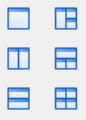
![]() Single View Layout — Designates a single panel viewing area.
Single View Layout — Designates a single panel viewing area.
![]() Two View Layout (Horizontal) — Designates two panels as viewing areas stacked side by side.
Two View Layout (Horizontal) — Designates two panels as viewing areas stacked side by side.
![]() Two View Layout (Vertical) — Designates two panels as viewing areas stacked one on top of the other.
Two View Layout (Vertical) — Designates two panels as viewing areas stacked one on top of the other.
![]() Three View Layout (Vertical) — Designates three panels as viewing areas arranged with one large panel on the left and two smaller panels stacked one on top of the other to the right of the large panel.
Three View Layout (Vertical) — Designates three panels as viewing areas arranged with one large panel on the left and two smaller panels stacked one on top of the other to the right of the large panel.
![]() Three View Layout (Horizontal) — Designates three panels as viewing areas arranged with one large panel on the top and two smaller panels side by side below the large panel.
Three View Layout (Horizontal) — Designates three panels as viewing areas arranged with one large panel on the top and two smaller panels side by side below the large panel.
![]() Four View Layout — Designates four panels as viewing areas with each panel taking up the same amount of room.
Four View Layout — Designates four panels as viewing areas with each panel taking up the same amount of room.
📝 NOTE: If you currently have a Single View Layout and change to a Two View Layout (either Horizontal or Vertical) Vericut will add the view with the type as defined below:
-
If the single view is a Workpiece View, the added view will be a Machine view.
-
If the single view is a Machine view, the added view is a Workpiece view.
If the default view is not the view type that you want, right mouse click in the added view and select View Type > desired view type (Workpiece, Machine, or Profile) from the right mouse button shortcut menu.
💡 Tip: You can also use the corresponding view layout icons in the Toolbar.
![]()
Changing the View Layout
Use the procedure described below to change the view layout in Vericut.
In the Vericut main menu ribbon, click View tab. In the Layout group, choose the option that provides the desired view quantity and layout.
| Single View Layout Two View Layout (Horizontal) Two View Layout (Vertical) |
 |
Three View Layout (Vertical) Three view Layout (Horizontal) Four View Layout |
|---|---|---|
💡 Tip: You can also use the corresponding view layout icons in the Toolbar.
![]()
With the view layout set, additional views can be added, or views can be deleted from the current layout using other functions in the View tab.
Drag or resize any of the view ports in the Vericut main window as desired via dragging the view port window header, sides or corners. View port size and layout are saved in the project file.
Adding or Deleting Views in the Vericut View Layout
Use the procedure described below to add, or delete, a view from the Vericut view layout.
To add a new view:
In the Vericut main menu ribbon, select View tab >  (Add View).
A new view is added. Reposition, or resize, views via dragging the view window header, sides, or corners.
To delete a view:
-
Click in the view that you want to delete so that it becomes the "active" view.
-
In the Vericut main menu ribbon, select View tab >
 (Delete View). The view is removed.
↘️ Shortcut: You can also delete a view via clicking "X" at the top right corner of the view window.
Tiling Views
Use the procedure described below to arrange views in a tiled layout. Example arrangements are shown below.
| View Type | Example |
|---|---|
| Tiled Horizontally |  |
| Tiled Vertically | 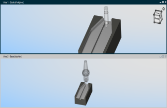 |
After any of these operations, you can reposition, or resize, any of the views via dragging the view window header, sides or corners.
To tile views horizontally:
In the Vericut main menu ribbon, select View tab >  (Tile Horizontally).
The view ports are arranged in a horizontal tiled arrangement as shown in the picture above.
To tile views vertically:
In the Vericut main menu ribbon, select View tab >  (Tile Vertically), depending on the desired orientation.
The view ports are arranged in a vertical tiled arrangement as shown in the picture above.