ZOLLER Database Access window
Locations:
Tool Manager > Tool Bar > Import tab >  (ZOLLER Database)
The ZOLLER Database Access window enables you to retrieve tool data from the ZOLLER Database Service and import selected tools from a setup sheet in the ZOLLER database into the Vericut Tool Manager. Cutting data can also be read in from ZOLLER TMS during the import process for use in toolpath optimization within Vericut and Tool Manager to run additional checks on your simulation.
📝 NOTE: The ZOLLER Database option is only displayed in the Import Tool menu when you have a ZOLLER TMS Interface license.
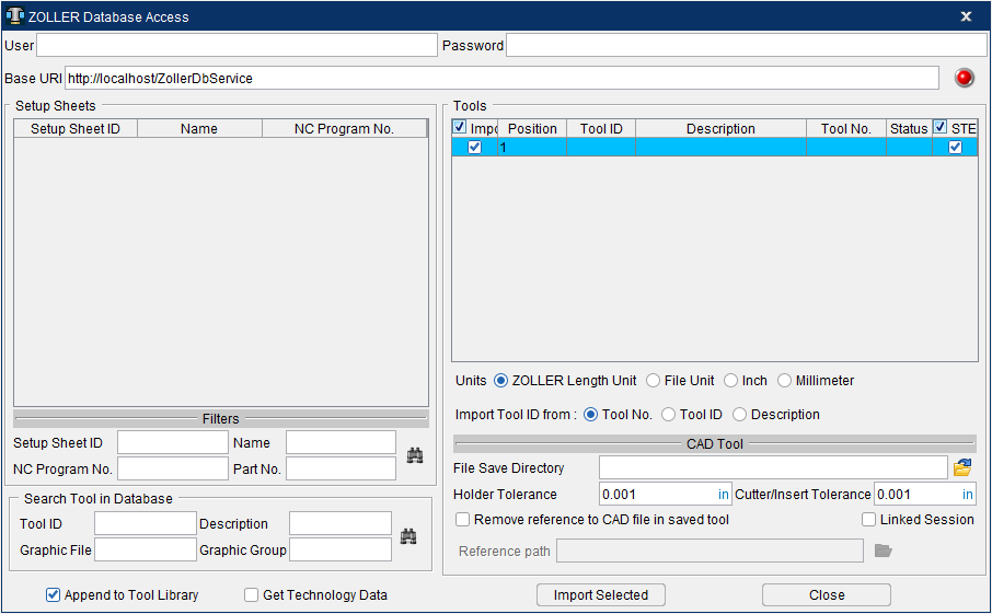
User — Enter your user name in the User text field.
Password — Enter your user password in the Password text field.
Base URI — Enter the base URI for the ZOLLER web service (protocol, hostname, optional port number and the service name) in the Base URI text field.
📝 NOTE: User, Password, Base URI are all saved in the preferences file.
Status Icon — The colored light on the Status icon indicates the result of the current action. Each light is described below.
Press the  /
/ /
/ (Status) icon to clear the list of tools in the Tools list and retrieve all setup sheets in the database and display them in the Setup Sheets list regardless of the Filters settings.
Result — The result lights indicate the result of the current action. Each light is described below.
| (Red light) — |
Bad Connection |
|---|---|
| (Light Green light) — |
Successful Connection |
| (Dark Green light) — |
No Record Found |
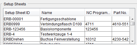
Setup Sheets — Displays a list of all setup sheets found in database.
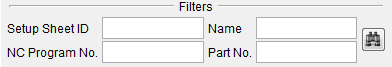
Filters — Use the following filters to search for a specific setup. Notice that each of the search filters corresponds to a column in the Setup Sheets list. Enter a value in one or all of the text fields and then press the  (Search Setup Sheets) icon to start the search.
-
Setup Sheet ID — Enter a Setup Sheet ID in the text field.
-
Name — Enter a Setup Sheet Name in the text field.
-
NC Program No. — Enter an NC program number in the text field.
-
Part No. — Enter a part number in the text field.
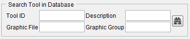
Search Tool in Database — Use the following additional search fields to browse the ZOLLER database to search for individual tools. Please note that wild card characters are not needed (i.e. entering ‘08’ will return any name with the characters in that field). Enter a value in one or all of the text fields and then press the (Search Setup Sheets) icon to start the search.
-
Tool ID — Search for tools using the ZOLLER Tool ID.
-
Description — Search for tools using the ZOLLER Description.
-
Graphic File — Search for tools using the file name of graphics or drawings.
-
Graphic Group — Search for tools using the group name that graphics/drawings are assigned to.
Append to Tool Library — When toggled on (checked), the Append to Tool Library option enables you to add the tools from the selected TDM list to those present in the currently accessed library. If there is a conflict between tool IDs, the tools already in the library will prevail. When this option is active, there will be no link between the project file and the TDM list, because the set of tools accessed by the project file is more comprehensive than the content of the TDM list.
Get Technology Data — when toggled on (checked), the Get Technology Data option enables you to ZOLLER’s technology data (performance parameters) of tools to use in optimization of the NC Program. This option remains modal until changed by the user. See Getting Technology Data for Use in Optimization for additional information.
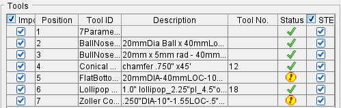
Tools — Selecting a setup sheet in the Setup Sheets list so that becomes highlighted will cause all tools associated with the selected setup to be retrieved and displayed in the Tools list.
-
Import — Toggle on (checked) to ensure that the selected tool is imported when Import Selected is clicked.
-
Position — Controls the position of the tool.
-
Tool ID — Transfer the ZOLLER Tool ID as the Vericut Tool ID.
-
Description — Transfer the ZOLLER Description as the Vericut Tool ID.
-
Tool No. — Transfer the ZOLLER Tool Number as the Vericut Tool ID.
-
Status — Provides feedback as tools are being read into Tool Manager:
 Displays when a tool is read in successfully.
  Displays when a tool fails to read in.
 -
STEP — Toggle on (checked) to ensure that a STEP model, if available, is read in when the tool is imported.
Units — Use to select the unit of measurement that will be imported. Options are as follows:
-
ZOLLER Length Unit — References the length unit that was set in the ZOLLER Database. To access this within the ZOLLER Database, go to ZOLLER Menu => "Single components" or "Manage tools" => right, next to "Id No." data field the "Extended tool setting" button => Here you can select the "Length unit" . If “Length unit” is set to 1, imported tool unit will be inch; If “Length unit” is set to 0, imported tool unit will be millimeter. If “Length unit” is not set, the default units in Tool Manager’s preference will be used.
-
DXF File Unit — References the length unit that was set in the DXF or STEP File. If the DXF File has “\(INSUNITS” set to “1”, tool unit will be inch; If “\)INSUNITS” is set to “4”, tool unit will be millimeter; otherwise the default units in Tool Manager’s preference will be used. For a STEP file the units will be read from file. The unit setting for STEP models will depend on what authoring software that created the STEP file.
-
Inch — Imports the tool(s) in inches. If data being read in is in a different unit, values will be converted to the desired unit.
-
Millimeter — Imports the tool(s) in millimeters. If data being read in is in a different unit, values will be converted to the desired unit.
Import Tool ID from —
-
Tool No — (Default) Uses the Tool No field of that specific tool to populate the Tool ID in Tool Manager
-
Tool ID — Uses the Tool ID field of that specific tool to populate the Tool ID in Tool Manager
-
Description — Uses the Description field of that specific tool to populate the Tool ID in Tool Manager
CAD Tool —
-
File Save Directory — (OPTIONAL) Allows for an optional location where the tool geometry files will be saved. The default location is the Working Directory.
-
Holder Tolerance — Enables you to specify the Holder Tolerance by entering the tolerance value in the Holder Tolerance text field. The default value is read from the Tool Manager > Utilities ribbon > Preferences dialog.
-
Cutter/Insert Tolerance — Enables you to specify the Cutter/Insert Tolerance by entering the tolerance value in the Cutter/Tolerance text field. The default value is read from the Tool Manager > Utilities ribbon > Preferences dialog.
Import Selected — Imports all of the tools in the Tools list to Vericut’ Tool Manager.
Close — Closes the ZOLLER Database Access window without importing tools to Vericut’s Tool Manager.
Saving the ZOLLER Tooling Data for Use in a Vericut Simulation
There are two options to work with/save the ZOLLER tool data for use in a Vericut simulation:
'Linked' session — No .tls file is saved. This option directly connects to the ZOLLER TMS each time the Vericut simulation is opened/run to pull the tools from the selected, named ZOLLER Setup Sheet. If the connection cannot be established to the ZOLLER TMS database, the 3D cutting tools cannot be accessed or displayed.
📝 NOTE: This option only works with the tools as they are defined in ZOLLER. No changes can be made to the tools in Vericut or Tool Manager in any way. The following options in the ZOLLER Interface will not be saved when working in a 'linked' mode.
-
Import column — no individual selected tools. All the tools in the ZOLLER Setup Sheet will be read into Tool Manager.
-
Append to Tool Library — toggled off (not checked) is default.
-
Remove reference to CAD file in saved tool — When toggled "off" (not checked), the imported tool models are stored in the same CAD format that they were imported in. When toggled "on" (checked), the imported tool components are saved as Vericut Polygon files.
-
Reference Path — The user can specify a path to where the polygon files will be saved. Reference path is only applicable when the “Remove reference to CAD file in saved tool” is toggled on (checked).
To save a 'linked' session, click the X in the upper right corner of the Tool Manager window without saving the .tls file to a location.
The ZOLLER Setup Sheet name will also appear in the Project Tree as shown below:

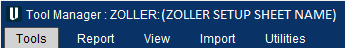
When reopening Tool Manager, the 'referenced' ZOLLER list will display in the Tool Manager's title bar as shown in the example below:
Saved .tls file — .tls file is created and saved. This option creates a copy of the 3D tool(s) for use in the Vericut simulation and stores the tooling data and information in a .tls file. If changes are made to the tools in the ZOLLER Setup Sheet, the list will need to be read into Tool Manager again. All above options (Import column, Append to Tool Library, and any ‘manual’ changes to tools) will apply and be saved accordingly.
To save the .tls file, click the Save File icon from the Tools tab.
Getting Technology Data for Use in Optimization
The ZOLLER TMS system has the option to store what is commonly known in Vericut as cutting limits and optimization settings along with the cutting tool geometry information. In ZOLLER TMS these cutting limits and optimization settings are referred to as Technology Data for each tool assembly. This Technology Data can be used in Vericut and Tool Manager to run additional checks on your simulation as well as be utilized with Force.
If you intend to run these additional checks and perform optimization (Force) on your NC Program, you will need to have the cutting limits and optimization settings for a particular tool assembly being used on a specific CNC machine cutting a specific material. These performance parameters may also be specific to each application of how that tool assembly is being used (I.e. roughing, semi-finishing, finishing, etc.)
The cutting limits and optimization settings are stored in Vericut’s Tool Manager in Stock Material Records, attached to the cutter of each Tool ID. Each Tool ID could have just one Stock Material Record or multiple depending on how the tool is used in your facility.
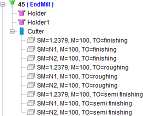
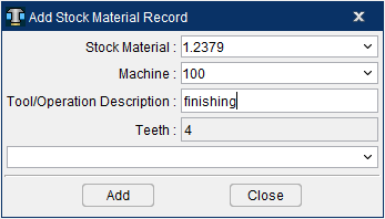
The name of the Vericut Stock Material Record is comprised of the following 3 pieces of information that is entered into the Add Stock Material Record window:
-
SM = (Stock Material) Name of the material that is being cut
-
M = (Machine) CNC machine name
-
TO = (Tool/Operation Description) Description of the application for this situation
When the Stock Material Record is created it is necessary to match the Stock Material and Machine names may not exactly match what is entered into the ZOLLER TMS software to what is entered in Vericut. The matching of the CNC machine and material names is necessary once you get into the optimization process in order to correctly match the Force Material File.
For the above described reasons, when Get Technology Data is toggled ON and the Import Selected button is clicked in the ZOLLER Database Access window, it will open the Machine and Material Mapping window.
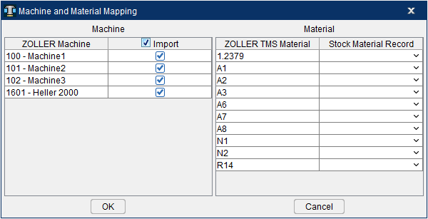
ZOLLER Machine — This will populate with all the CNC machine names relating to all the tools from that Setup Sheet
Vericut Machine — This pulldown will display all machine names listed in Vericut under the Optimize ribbon > Optimize Control > Optimization tab > Machine. The list will also allow for a name to be typed in. The default will display empty field. If Tool Manager is being run as stand-alone (not launched from Vericut) there will not be any machine names listed under the pulldown.
ZOLLER TMS Material — This will populate with all the material names relating to all the tools from that Setup Sheet
Stock Material Record — Displays the Stock Material Record names that are available from the Force Material File Directory in Vericut and any Stock Materials listed in Tool Manager. A new Stock Material name can be entered in this field if desired. This optional selection is intended to align existing Stock Material Records within Vericut to a Workpiece Material name. This option is for use with Force and Optimization. The default will display empty field. If Tool Manager is being run as stand-alone (not launched from Vericut) there will not be any material names listed under the pulldown.
OK — Will continue to read in each tool from the Setup Sheet and create Stock Material Records for all records with a Machine and Material mapped. If either the Machine or Material is not mapped for that specific application, the tool will be generated without a Stock Material Record.
Cancel — Closes the Machine and Material Mapping window without creating any tools in Tool Manager and returns to the ZOLLER Database Access window.
📝 NOTE: The mapping of only a certain CNC machine name or a certain material name versus mapping every CNC machine name and material name will depend on your workflow. If you are only concerned with getting Stock Material Records for a specific CNC machine and material you are simulating then only map the specific desired CNC machine and material you need. If you are doing a master tool library where you want any and all CNC machines and materials for a given tool, then all map all the CNC machines and materials accordingly to read in all Stock Material Records along with your tools.