Tabbed Cards
The tabbed cards represent the five steps you perform to create an NC program, plus a Settings card to define the display settings for the Fastener Programming window. The tabbed cards are organized, from left to right, in the order you perform the steps.
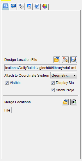
Design Locations card — Enables you to add, delete, or save a Design Locations file, specify the coordinate system the Design Locations data is attached to, set the visibility of the Design Location data in the graphics area, and merge a new Design Locations file with the current Design Locations file.
Sequencing card — Enables you to add, delete, or rename a sequence of drilled hole/fastener locations to your NC program.
Set Post Processor Options card — Enables you to specify the post processor file to be used for each sequence of fastener locations and enables you to assign a cycle to each fastener location.
Transition Paths card — Enables you to define a path for transitioning between fastener locations and between sequences of locations. Also enables you to define approach and retract points for complex transition paths.
Run Post to Generate NC Program card — Enables you to select the sequences you want to post process, select the coordinate system to be used for the positions and direction vectors, enter comments for the NC program, specify the name and location of the NC program file, run post processing and add the NC program to the project file.
Settings card — Enables you to specify the colors that certain objects will be displayed in the graphics area of the Fastener Programming window.