Design Locations card
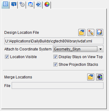
Design Locations File — A Design Locations File initially contains the fastener location data. As you program the drilling and fastening actions data is added to the Design Locations File. After post-processing the data, the NC program can be simulated using Vericut Drilling and Fastening Simulation to find and correct programming errors.
The Design Locations File is then used by AUTO-DIFF to compare data collected during simulation with the design location data in the Design Locations File.
The Design Locations File is described in detail below in the Design Locations File section.
Use the following features to open, or save, an existing Design Locations file:
-
 (Open File) — Displays the "Open a fastener design locations file" file selection window enabling you to specify the /path/filename of the Design Locations file to be used.
 -
 (Remove Design) — Permanently deletes the Design Locations file from the project.
 -
 (Save File) — Displays the "Save a fastener design locations file" file selection window enabling you to specify the /path/filename of the location where the Design Locations file is to be saved.
Attach to Coordinate System — Use to specify the coordinate system that the Design Locations data is to be attached to. Select the coordinate system from the pull-down list.
Location Visible — Use to turn the display of the Design Locations data "on" (checked) and "off" in the graphics area. Visibility can also by toggled on or off for each individual Location ID by using the Visible column.
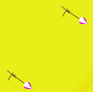
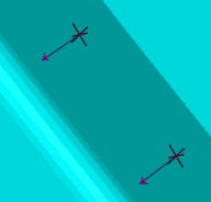
Display Stays on View Top — When toggled on (checked) the Design Locations markers are always drawn on top of the view regardless their 3D Z depth.
| Display Stays on View Top “off” | Display Stays on View Top “on” |
|---|---|
 |
 |
| View “Reversed” | View “Reversed” |
 |
 |
Show Projection Stacks — When toggled “on” (checked), projection stacks are displayed.
| Display Stays on View Top = “off” Show Projection Stacks = “on” | Display Stays on View Top = “on” Show Projection Stacks = “on” |
|---|---|
 |
 |
| View “Reversed” | View “Reversed” |
|
 |
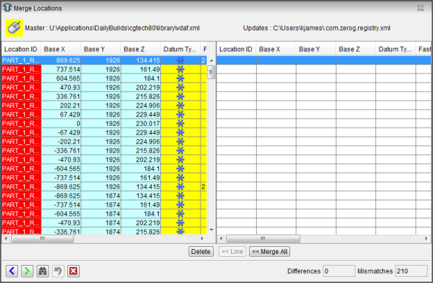
Merge Locations File — A Merge Locations File initially contains fastener location data that may be different from the Design Location file.
-
(Open File) — Displays the "Merge locations file" file selection window enabling you to specify the /path/filename of the Merge Locations file to be used. After you select the file you want to merge with the current file, the Merge Locations window is displays the differences between the Design Location file (left) and Merge Locations file (right).
-
 (Delete) — If the Design Location file contains a data point that is not contained in the Merge Locations file, the Delete button becomes available. Highlight the data point you want to delete and click Delete to remove the data point from the Design Location file.
 -
 (Line) — If the Design Location file contains a data point with values that are different from those contained in the Merge Locations file, the Line button becomes available. Highlight the data point you want to change and click Line. The information for the data point from the Merge Location file overwrites the information for the data point in the Design Location file.
 -
 (Merge All) — Enables the Merge Location file to overwrite the Design Locations file.
 -
 (Previous Mismatch) — Highlights the previous mismatch in the Design Locations file.
 -
 (Next Mismatch) — Highlights the next mismatch in the Design Locations file.
 -
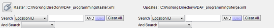
 (Search) — Clicking on the Search icon displays the Merge Locations search tool to assist you in finding the information that you need in the Merge Locations window. Initially the search tool will display as shown in the following picture.
-
The search criteria on the left allow you to search the Design Locations file. The search criteria on the right allow you to search the Merge Locations file. These two search areas work independently from each other.
-
Search — the Search pull-down list contains all of the search categories that are available. Each of the categories corresponds to a column header in the Design Locations Table. Each of these categories will be described in the Design Locations Table section below.
-
Selecting a category will change the way that the search tool looks depending on the supporting information needed to conduct the search. An And Search / Or Search pull-down list, depending on the AND / OR setting, is also automatically added. Each of these features is described below.
-
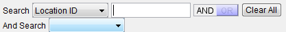
The following search tool configuration applies to the following search categories: Location ID, Fastener ID, and Fastener Type.
-
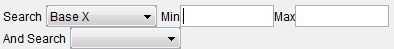
The following search tool configuration applies to the following search categories: Base X, Base Y, and Base Z.
-
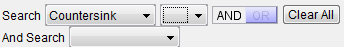
The following search tool configuration applies to the following search categories: Countersink, Fastener Type and Datum Type.
-
Min/Max — use the Min and/or Max fields to specify a number, or range of numbers, associated with the selected search category to define the bounds of the search. The result of using different Min/Max combinations is described below.
Entering a Min value and a Max value will display all rows between the Min value and the Max value including the specified values.
Entering a Min value that does not exist will display the row with closest larger value than the one specified.
Entering the same Min and Max values will display the row with the specific value specified.
Entering a Min value and a blank Max value will display all rows with values greater than or equal to the specified Min value.
Entering a blank Min value and a Max value will display all rows with values less than or equal to the specified Max value. -
text field — use the text field to enter a text string associated with the selected search category to define the bounds of the search. The result of using different text strings in the text field is described below for each search category that uses a text field.
-
AND / OR — use AND or OR to specify multiple conditions for the search. AND indicates that if both conditions are met, include the row in the resulting list. OR indicates that if either of the conditions is met, include the row in the resulting list.
-
Clear All — use to clear all entered search parameters and return the search tool to its initial state.
-
And Find / Or Find — these features work in the same way as the Search feature described above.
-
-
 (Undo) — Use this icon to “undo” changes made in the Merge Locations window. The icon will be grayed out until a change is made in the Merge Locations window. Once a change is made in the Merge Locations window the icon will display as shown here. Click on the icon to “undo” the last change made to the Merge Locations window. Click on the icon again to “undo” the next to the last change and so on. There is no limit to the number of changes that you can “undo”.
 -
 (Close) — Use this icon to close the Merge Locations window.
![]() (Merge Location Files ) — The name of the Design Location file to be merged with the current Design Locations file.
(Merge Location Files ) — The name of the Design Location file to be merged with the current Design Locations file.