Settings card
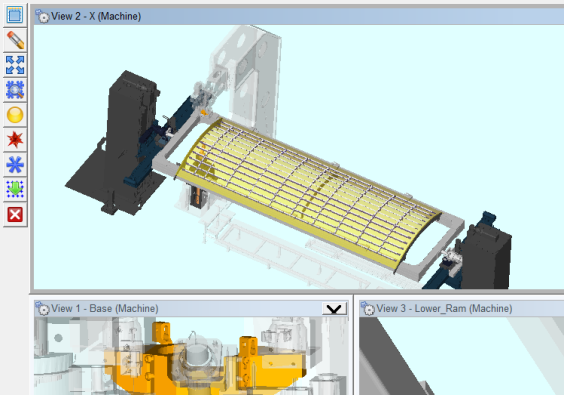
Display Side Toolbar — When toggled “on” (checked), Side Toolbar at the upper left corner of the Vericut Drill and Fastener graphics area as shown in the picture below. The Side Toolbar contains tools to assist you in selecting hole and fastener locations.
 (Select all locations) — Selects all rows on the Design Location table.
![]() (Clear Selection) — Clears (de-selects) all selections on the Design Location table.
(Clear Selection) — Clears (de-selects) all selections on the Design Location table.
 (Fit locations to all views) — Use to “fit” the model to the size of the current view.
![]() (Use mouse to select or un-select locations by box) — Toggles between selecting and de-selecting fastener locations by drawing a box around the desired locations in the graphics area.
(Use mouse to select or un-select locations by box) — Toggles between selecting and de-selecting fastener locations by drawing a box around the desired locations in the graphics area.
 (Set selected locations as local datums) — When locations are select in the Design Location table, use this option to set the selected locations as local datums.
 (Set selected locations as global datums) — When locations are select in the Design Location table, use this option to set the selected locations as global datums.
 (Set selected locations as non-datums) — When locations are select in the Design Location table, use this option to set the selected locations as non-datums.
 (Re-project all sequence locations) — When the Design Locations file is specified on the Design Location card, the fastener locations are projected onto the skin. Use this option to re-project all of the fastener locations for the selected sequence.
![]() (Close) — Closes the Side Toolbar.
(Close) — Closes the Side Toolbar.
Adjust Location Mark Scale — Use to change the size of the location mark and vector displayed in the graphics area. Scale value is saved in the project file. Each time you click on the ![]() (up arrow) icon, the location mark and vector are displayed larger. Each time you click on the
(up arrow) icon, the location mark and vector are displayed larger. Each time you click on the ![]() (down arrow) icon, the location mark and vector are displayed smaller. See the pictures below:
(down arrow) icon, the location mark and vector are displayed smaller. See the pictures below:
Location Marks displayed small.
![]()
Location Marks two "clicks" on the
![]() (up arrow)
larger.
(up arrow)
larger.

The Adjust Location Mark Scale is saved in the project file.
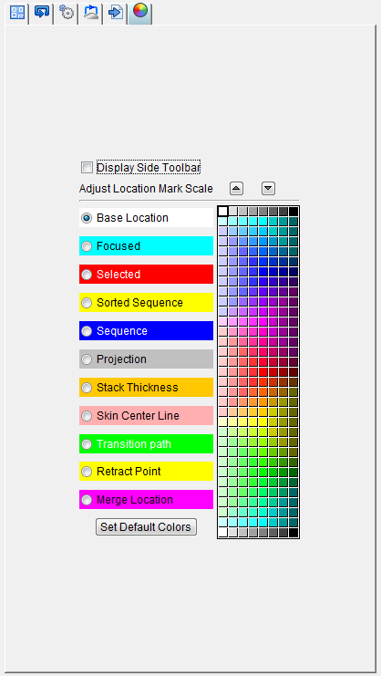
Colors
Use to specify the colors that certain objects will be displayed. Select any of the categories on the left side of this card, and then select a color from the color palette on the right side of the card. You can continue to select colors until you get the appearance you want. The following objects are available for color selection:
-
Base Location — pecifies the color of the form
-
Focused — Specifies the color of the drilled hole/fastener location when the mouse is hovered over the location.
-
Selected — Specifies the color of the drilled hole/fastener location(s) that have been selected either by clicking the location or selecting the location by box.
-
Sorted Sequence — Specifies the color of the drilled hole/fastener location(s) that have been assigned to a sequence and sorted on the Sequencing card.
-
Sequence — Specifies the color of the drilled hole/fastener location(s) that have been assigned to a sequence on the Sequencing card.
-
Projection — Specifies the color of the projection of the drilled hole/fastener location(s) onto the surface of the skin.
-
Skin Center Line — Specifies the color of the point at the center line of the skin.
-
Transition Path — Specifies the color of the transition path that have been designated on the Transition tab of the Transition Paths card.
-
Retract Point — Specifies the color of the locations that have been designated as retract points on the Retract Points tab of the Transition Paths card.
-
Merge Location — Specifies the color of the merge locations that have been specified on the Design Locations card.
-
Color Palette — The Color Palette icon enables you to specify the color that you want to be used for the selected item in the graphics area of the Fastener Programming window.
When an item is selected on the left side, the Color Palette shows the current color for that item. To change the color for the selected item, click on a color in the Color Palette.
Set Default Colors — If you wish to return to the original set of colors, simply click on the "Set Default Colors" button.