Design Locations File
The Design Locations File is displayed to the right of the Tabbed cards as a table. The table initially contains the fastener location data and data is added to it as you program the drilling and fastening actions. A sample Design Locations table is shown in the picture below.
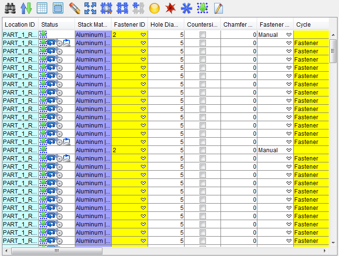
Each row in the Design Locations table represents the information related to a single drilled hole/fastener location
When a row is selected in the Design Locations table it becomes highlighted in the table, the corresponded drilled hole/fastener location in the graphics area becomes highlighted. You can also select a drilled hole/fastener location in the graphics area and the corresponding row in the Design Locations table becomes highlighted.
Table Manipulation Toolbar

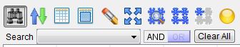
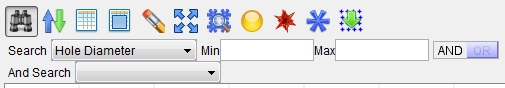
![]() (Search) — Clicking on the Search icon displays the Design Locations search tool below the Table Manipulation Toolbar to assist you in finding the information that you need in the Design Locations Table. Initially the search tool will display as shown in the following picture.
(Search) — Clicking on the Search icon displays the Design Locations search tool below the Table Manipulation Toolbar to assist you in finding the information that you need in the Design Locations Table. Initially the search tool will display as shown in the following picture.
Find — The Find pull-down list contains all of the search categories that are available. Each of the categories corresponds to a column header in the Design Locations Table. Each of these categories will be described in the Design Locations Table section below.
Selecting a category will change the way that the search tool looks depending on the supporting information needed to conduct the search. An And Find / Or Find pull-down list, depending on the AND / OR setting, is also automatically added. Each of these features is described below.
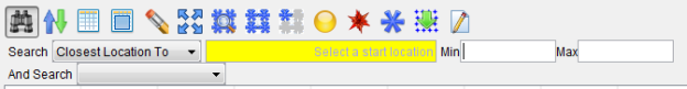
The following search tool configuration applies to the following search categories: Closest Location To, Closest Machine X To and Closest Machine Y To.
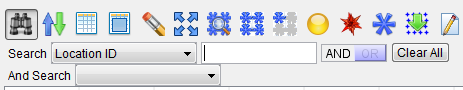
The following search tool configuration applies to the following search categories: Location ID, Stack Material, Cycle, Fastener ID, Stack Thickness, Skin Surface, Region, Description and Sequence.
The following search tool configuration applies to the following search categories: Hole Diameter, Chamfer Depth, Machine X, Machine Y, Base X, Base Y, Base Z, Projected X, Projected Y, Projected Z, Normal I, Normal J, Normal K, Length, Head Angle and Color.
The following search tool configuration applies to the following search categories: Countersink, Fastener Type and Datum Type.
Min/Max — Use the Min and/or Max fields to specify a number, or range of numbers, associated with the selected search category to define the bounds of the search. The result of using different Min/Max combinations is described below.
Entering a Min value and a Max value will display all rows between the Min value and the Max value including the specified values.
Entering a Min value that does not exist will display the row with closest larger value than the one specified.
Entering the same Min and Max values will display the row with the specific value specified.
Entering a Min value and a blank Max value will display all rows with values greater than or equal to the specified Min value.
Entering a blank Min value and a Max value will display all rows with values less than or equal to the specified Max value.
Text field — Use the text field to enter a text string associated with the selected search category to define the bounds of the search. The result of using different text strings in the text field is described below for each search category that uses a text field.
AND / OR — Use AND or OR to specify multiple conditions for the search. AND indicates that if both conditions are met, include the row in the resulting list. OR indicates that if either of the conditions is met, include the row in the resulting list.
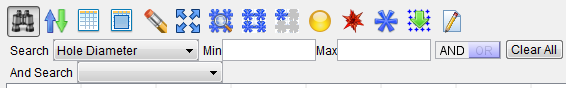
Clear All — Use to clear all entered search parameters and return the search tool to its initial state.
And Find / Or Find — These features work in the same way as the Find feature described above.
To use each search category:
Closest Location To — Use to search for the location closest to a point you select in the graphic view.
Closest Machine X To — Use to search for the location on the X axis closest to a point you select in the graphic view.
Closest Machine Y To — Use to search for the location on the Y axis closest to a point you select in the graphic view.
Location ID — Use the text field to enter a Location ID, or part of the Location ID to be used for the search.
Examples:
-
Entering 15 in the text field will list all rows containing the 15 text string (15, 115, 150, etc.).
-
Entering 22 in the text field will list all rows containing the 22 text string (22, 122, 220, 221, 222, etc.).
Stack Material — Use the text field to enter a Stack Material, or part of a Stack Material text string, to be used for the search.
Example:
For a Stack Material value of Aluminum | Titanium, Aluminum is the "Skin" stack material and Titanium is the "Structure" stack material.
You can use any part, or all, of the "Skin" stack material text string or any part, or all, of the "Structure" stack material text string for searching. For example Aluminum and Alum will provide the same result as long as the Design Locations table does not contain another Stack Material that begins with Alum.
Entering Aluminum in the text field will list all rows containing the Aluminum text string in either the "Skin" or "Structure" stack material or both the "Skin" and "Structure" stack material.
Aluminum | Titanium

Aluminum | Composite

Aluminum | Aluminum

        etc.
Entering Aluminum | Titanium in the text field will list all rows containing the Aluminum | Titanium text string.
Fastener ID — Use the text field to enter a Fastener ID, or part of a Fastener ID text string, to be used for the search.
Examples:
Entering 1 in the text field will list all rows containing the 1 text string (1, 15, 115, 150, etc.).
Entering 22 in the text field will list all rows containing the 22 text string (22, 122, 220, 221, 222, etc.).
Hole Diameter — Use Min and Max fields to define the range of Hole Diameter values that you want to search for in the table.
Countersink — Select No from the pull-down list to display all rows that have the Countersink checkbox toggled off (not checked). Select Yes from the pull-down list to display all rows that have the Countersink checkbox toggled on (checked).
Chamfer Depth — Use the Min and Max fields to specify the range of Chamfer Depth values that you want to search for in the table.
Fastener Type — Select Not Defined, Temporary, or Permanent from the pull-down list. All rows with the specified Fastener Type will be displayed.
Cycle — Use the text field to enter a Cycle, or part of a Cycle text string, to be used for the search.
Machine X — Use the Min and Max fields to specify the range of Machine X values that you want to search for in the table.
Machine Y — Use the Min and Max fields to specify the range of Machine Y values that you want to search for in the table.
Datum Type — Select the Datum Type (Not Defined, Not Datum, Local Datum, or Global Datum) from the pull-down list that you want to search for in the table.
Base X — Use the Min and Max fields to specify the range of Base X values that you want to search for in the table.
Base Y — Use the Min and Max fields to specify the range of Base Y values that you want to search for in the table.
Base Z — Use the Min and Max fields to specify the range of Base Z values that you want to search for in the table.
Projected X — Use the Min and Max fields to specify the range of Projected X values that you want to search for in the table.
Projected Y — Use the Min and Max fields to specify the range of Projected Y values that you want to search for in the table.
Projected Z — Use the Min and Max fields to specify the range of Projected Z values that you want to search for in the table.
Normal I — Use the Min and Max fields to specify the range of Normal I values that you want to search for in the table.
Normal J — Use the Min and Max fields to define the range of Normal J values that you want to search for in the table.
Normal K — Use Min and Max fields to define the range of Normal K values that you want to search for in the table.
Length — Use Min and Max fields to define the range of Length values that you want to search for in the table.
Stack Thickness — Use the text field to enter a Stack Thickness, or part of a Stack Thickness text string, to be used for the search.
Example:
For a Stack Thickness value of 7.632 | 6.351, the 7.632 is the "Skin" stack thickness and 6.351 is the "Structure" stack thickness.
You can use any part, or all, of the "Skin" stack thickness text string or any part, or all, of the "Structure" stack thickness text string for searching.
Entering 49 in the text field will list all rows containing the 49 text string in either the "Skin" or "Structure" stack thickness or both the "Skin" and "Structure" stack thickness.
11.649 | 6.353

7.774 | 6.349

7.496 | 6.349

      etc.
Skin Surface — Use the text field to enter a Skin Surface name, or part of a Skin Surface name text string, to be used for the search.
Region — Use the text field to enter a Region name, or part of a Region name text string, to be used for the search.
Head Angle — Use Min and Max fields to define the range of Head angle values that you want to search for in the table.
Description — Enter the Description text that you want to search for in the text field.
Color — Use Min and Max fields to define the range of Color values that you want to search for in the table.
Sequence — Use the text field to enter a Sequence name, or part of a Sequence name text string, to be used for the search.
Program Thickness — Use the text field to enter a Program Thickness, or part of a Program Thickness text string, to be used for the search. This feature works the same way as Stack Thickness. See the example for Stack Thickness above.
Program Material — Use the text field to enter a Program Material, or part of a Program Material, to be used for the search. This feature works the same way as Stack Thickness. See the example for Stack Material above.
Stack Count — Use the Min and Max fields to define the range of Stack Count values that you want to search for in the table.
Program Stack Count — Use the Min and Max fields to define the range of Program Stack Count values that you want to search for in the table.
Error Message — Use the text field to enter a key word, or words, from an error message to define the type of errors that you want displayed in the list. For example: fastener, material, countersink, stack count, etc.
![]() (Close) — Closes the Design Locations window.
(Close) — Closes the Design Locations window.
![]() (Sort) — Displays the Design Locations sort tool below the Table Manipulator Toolbar where you can enter the criteria by which you want to sort the list.
(Sort) — Displays the Design Locations sort tool below the Table Manipulator Toolbar where you can enter the criteria by which you want to sort the list.
-
Sort by — The Sort by pull-down list contains all of the sort categories available. Each of these categories will be described in the Using Sort section below.
-
Then by — The Then by pull-down list contains all of the sort categories available. Each of these categories will be described in the Using Sort section below.
Using Each Sort Category
Closest Location To — Use to sort locations starting with the location closest to a point you select in the graphic view.
Closest Machine X To — Use to sort locations on the X axis closest to a point you select in the graphic view.
Closest Machine Y To — Use to sort locations on the Y axis closest to a point you select in the graphic view.
-
Location ID — Sorts the list alphanumerically according to the Location ID.
-
Stack Material — Sorts the list alphanumerically according to the name of the Stack Material.
-
Fastener ID — Sorts the list alphanumerically according to the Fastener ID.
-
Hole Diameter — Sorts the list numerically, from lowest to highest, according to the hole diameter.
-
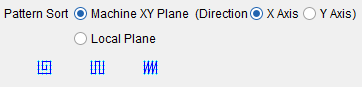
Pattern Sort —
-
Machine XY Plane Direction X Axis — Sorts the locations according to the Machine X axis.
-
Machine XY Plane Direction Y Axis — Sorts the locations according to the Machine Y axis.
-
Local Plane — Sorts the locations according to a local plane you create by selecting a first and second location within the graphics for the plane to reside along.
-
 Enables you to select a starting drilled hole/fastener location and sort locations by boundary.
 -
 Enables you to select a starting drilled hole/fastener location and sort locations bi-directionally.
 -
 Enables you to select a starting drilled hole/fastener location and sort locations on a single direction.
 /
/
 (Apply edits to current row) — Toggles between applying changes to the current row and applying changes to all rows.
 (Select all locations) — Selects all drilled hole/fastener locations in the Design Location table and highlights all drilled hole/fastener locations in the graphics area.
![]() (Clear Selection) — Unselects all drilled hole/fastener locations in the Design Locations table and deselects all drilled hole/fastener locations in the graphics area.
(Clear Selection) — Unselects all drilled hole/fastener locations in the Design Locations table and deselects all drilled hole/fastener locations in the graphics area.
 (Fit locations to all views) — Use to “fit” the model to the size of the current view in the graphics area.
![]() (Use mouse to select or un-select locations by box) — Use to draw a box in the graphics area around the drilled hole/fastener locations you want to select or unselect.
(Use mouse to select or un-select locations by box) — Use to draw a box in the graphics area around the drilled hole/fastener locations you want to select or unselect.
 (Show all locations) — Use to make all design locations visible.
 (Show selected locations) — Use to make all selected design locations visible.
 (Set selected locations as local datums) — Use to set the selected locations as local datums.
 (Set selected locations as global datums) — Use to set the selected locations as global datums.
 (Set selected locations as non-datums) — Use to set the selected locations as non-datums.
 (Re-project all sequence locations) — When the Design Locations file is specified on the Design Location card, the fastener locations are projected onto the skin. Use this option to re-project all of the fastener locations for the selected sequence.
![]() (Run post to generate program) — Click on this button once you have set the post-processor parameters as desired to generate the NC program file. Only the selected sequences will be post-processed into the NC program file.
(Run post to generate program) — Click on this button once you have set the post-processor parameters as desired to generate the NC program file. Only the selected sequences will be post-processed into the NC program file.
Design Locations Table
The Design Locations table consists of 29 columns of information related to each drilled hole/fastener location represented in the table. Each row represents an individual drilled hole/fastener location.
The information for columns with a  background comes from the NC program. The information for columns with a
  background comes from the simulation. The information for columns with a
  background are input by the user.
Location ID — The location ID specified in the NC program for the current drilled hole/fastener location.
Status — The status of the programming process.
-
 — The fastener location has been assigned to a sequence and the points have been projected onto the skin.
 -
 — The post processor has been defined and a cycle has been assigned to the drilled hole/fastener location.
 -
 — A transition path has been defined for the drilled hole/fastener location.
Cycle — The cycle field indicates the type of cycle that was executed at the current drilled hole/fastener location. For example, "Drill", or "Drill and Insert".
Head Angle — The angle of the anvil under the structure.
Fastener ID — The fastener ID identifies the fastener specified in the NC program that is to be used at the current drilled hole/fastener location. A blank fastener ID field would indicate just a drilled hole at the current location.
Stack Material — The stack material defined in the Project file for the current drilled hole/fastener location. The Stack Material value in the Design Locations table includes both the "Skin" stack material and the "Structure" stack material. For a Stack Material value of Aluminum | Titanium, Aluminum is the "Skin" stack material and Titanium is the "Structure" stack material.
Hole Diameter — The hole diameter at the current drilled hole/fastener location.
Countersink — The countersink status of the hole, specified in the NC program, for the current drilled hole/fastener location. A check in the box indicates a countersunk hole. No check indicates that the hole is not countersunk.
Chamfer Depth — The chamfer depth at the current drilled hole/fastener location.
Fastener Type — The fastener type indicates the type of fastener being used at the current drilled hole/fastener location.
-
Undefined — A blank fastener type field indicates that the type for fastener being used at the current location was not defined in the NC program.
-
Temporary — Temporary indicates that the fastener being used at the current location is a temporary fastener that will be replaced in a downstream operation.
-
Permanent — Permanent indicates that a permanent fastener is being used at the current drilled hole/fastener location.
-
Manual — Manual indicates that a manually-placed fastener is being used at the current drilled hole/fastener location.
Machine X — The X-axis value of the drilled hole/fastener projected onto the skin surface.
Machine Y — The Y-axis value of the drilled hole/fastener projected onto the skin surface.
Datum Type —
-
Not Defined — Blank indicates that the location has not been defined as a datum point.
-
Not Datum — Highlights all locations that have been defined as a non-datum, indicated by a
 in the Design Locations table Data Type column.
 -
Local Datum — Highlights all locations that have been defined as a local datum, indicated by a
 in the Design Locations table Data Type column.
 -
Global Datum — Highlights all locations that have been defined as a local datum, indicated by a
 in the Design Locations table Data Type column.
Base X — The X-axis location of the drilled hole/fastener location from the Design Location file.
Base Y — The Y-axis location of the drilled hole/fastener location from the Design Location file.
Base Z — The Z-axis location of the drilled hole/fastener location from the Design Location file.
Projected X — The X component of the vector representing the projection of the active tool component, along its z-axis, to the current drilled hole/fastener location on skin component.
Projected Y — The Y component of the vector representing the projection of the active tool component, along its z-axis, to the current drilled hole/fastener location on skin component.
Projected Z — The Z component of the vector representing the projection of the active tool component, along its z-axis, to the current drilled hole/fastener location on skin component.
Normal I — The I component of the surface normal vector of the skin component at the current drilled hole/fastener location.
Normal J — The J component of the surface normal vector of the skin component at the current drilled hole/fastener location.
Normal K — The K component of the surface normal vector of the skin component at the current drilled hole/fastener location.
Stack Thickness — The stack thickness calculated from model thickness at the current drilled hole/fastener location. The Stack Thickness value in the Design Locations table includes both the "Skin" stack thickness and the "Structure" stack thickness. For a Stack Thickness value of 7.632 | 6.351, the 7.632 is the "Skin" stack thickness and 6.351 is the "Structure" stack thickness.
Skin Surface — The name of the skin component.
Region — The region of the drilled hole/fastener location as defined in the Design Location file.
Description — The description of the drilled hole/fastener location as defined in the Design Location file.
Color — The color of the drilled hole/fastener location as defined in the Design Location file.
Sequence — The sequence number of the sequence to which the drilled hole/fastener location is assigned.
Program Thickness — The stack thickness specified in the NC program at the current drilled hole/fastener location. The Program Thickness value in the Design Locations table includes both the "Skin" stack thickness and the "Structure" stack thickness. For a Program Thickness value of 7.7 | 6.35, the 7.7 is the "Skin" stack thickness and 6.35 is the "Structure" stack thickness.
Program Material — The stack material defined in the NC program for the current drilled hole/fastener location. The Program Material value in the Design Locations table includes both the "Skin" stack material and the "Structure" stack material. For a Stack Material value of Aluminum | Titanium, Aluminum is the "Skin" stack material and Titanium is the "Structure" stack material.
Stack Count — The stack count is the total number of layers specified in the Project file at the current drilled hole/fastener location. The stack count includes the "Skin" layer and one or more "Structure" layers.
Program Stack Count — The program stack count is the total number of layers specified in the NC program at the current drilled hole/fastener location. The stack count includes the "Skin" layer and one or more "Structure" layers.
Error — Provides a visual indication that an error has occurred at the current drilled hole/fastener location. The ![]() symbol in the error field indicates that an error has occurred.
symbol in the error field indicates that an error has occurred.
Error Message — The text in the error message field describes the error that occurred at the current drilled hole/fastener location. For example, "Fastener 1's countersink type does not match holes at line 101."
Design Locations Table Right Mouse Button Menu
The features in the Design Locations file, right mouse button menu enable you to display the search tool as well as providing tools that enable you to configure the Design Locations table in a manner that best suits your specific needs.
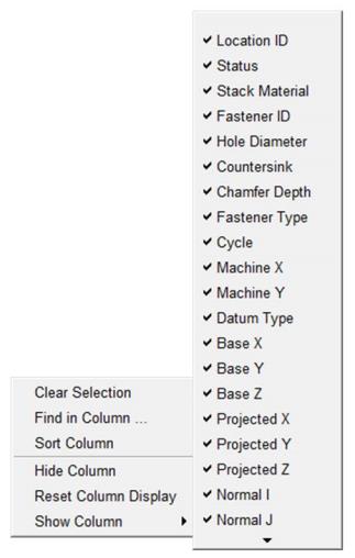
Clear Selection — Unselects all selected drilled hole/fastener locations in the Design Locations table and deselects all selected drilled hole/fastener locations in the graphics area.
Find in Column — Displays the search tool immediately below the toolbar. This feature provides the same functionality as the Search icon ![]() described above.
described above.
Sort Column — Enables you to sort the Design Locations table according to the values in a specific column. Click the column heading of the column you want to sort by and then right-click and select Sort Column from the menu that displays.
Hide Column — Enables you to hide columns in the Design Locations table. Click with the right mouse button in the column that you want to hide and then select Hide Column from the menu that displays.
Reset Column Display — Enables you to reset the columns in the Design Locations table to the default condition (all columns displayed).
Show Column — Clicking on Show Column displays a list of all columns available for display in the Design Locations table and its current status. A check next to an item indicates that the item is currently displayed in the Design Locations table. Click on an item in the list to toggle between displayed (checked) and a not displayed.
When displaying a column, right click in the column to the right of the location where you want the column displayed to display the menu. When you select the column that you want displayed, it will be inserted immediately to the left of the column you opened the menu in.
Hold the cursor over the ![]() at the bottom of the list to view additional columns.
at the bottom of the list to view additional columns.
💡 Tips:
-
If the column did not get displayed where you wanted, click in the column header and drag the column to the right, or left, to the desired position. You can do this with any column, at any time.
-
You can change the width of each column by clicking on the divider between headers and then moving the divider to the left or right to make the column width smaller or larger