Application Specific Post-Processor Information
The following sections describe the basic construct and features used for creating a post-processor related to a specific Vericut application. The specific information for each application is described in the following sections:
Vericut Inspection Probe Cycle Programming
Vericut Inspection Probe Cycle Programming
Introduction
Vericut can be used to generate G-Code files that drive an NC machine through the steps required to inspect a workpiece with one or more probes. Once you have picked the features that are to be inspected, you can use the  (Use probe for all features) icon to specify that each of them will be probed. Then the
  (Program probe cycles) icon will present the Inspection Programming window, and prompt you to select a post-processor language file. By convention such a file should have the extension ".VcPost".
Probe cycle programming uses the post-processor language file to determine how to format the output G-Code files. In addition, comments within the file are used to define the names of the probe cycles available on the target machine, and the names of each cycle's parameters. Both types of names get displayed in the programming dialog's table, and the user is expected to pick a cycle which is appropriate for measuring each feature, and to provide numeric values for at least some of its parameters. This document is primarily concerned with defining the syntax of the comments.
There are eight keywords used in the probe cycle comments, each of which starts with the character "#". The keywords are;
| #Init | #End | #Rapid | #Move | #Approach | #Retract | #Cycle | #Save |
|---|---|---|---|---|---|---|---|
A subroutine or "Sub" within the post-processor language file can employ at most just one of these keywords. It may have more than one comment line with the same keyword. Such comment lines must be between the "Sub" and "End Sub" statements.
In addition to the keyword, any of the comment lines can also contain parameter names, which should be separated by spaces. Each parameter name will be used as the name of a register in the post-processor, so the name must conform to the rules for variable names. They must start with a letter and can only contain letters, numerals and the underscore character, "_". Note that there are language keywords that cannot be used as parameter names. Parameters can be essential to the interpretation of a probe cycle, or optional. An exclamation mark, "!", preceding a parameter's name in the comment line declares it as mandatory. The syntax should become much clearer in the following examples.
#Init
There should only be one subroutine containing a comment line with the #Init keyword, and it will be invoked once, before any other subroutines, when the post-processor is run. For example, if the following is defined in the post-processor language file,
Sub Initialize()

  ' #Init Offset Clearance FeedRate

  Out "<N> G17"

End Sub
then the first row in the inspection programming table will initially look like this.

Note that it is the name of the subroutine, "Initialize", that appears in the "Cycle" column of the table. So you can alter the prompt in the table to match the user's language and preferences. The parameter names that follow the #Init keyword on the comment line will appear in the numbered columns, in the order they are listed. If you need more parameters than can comfortably fit on one comment line, simply add more lines, each with the #Init keyword. There is a maximum of 16 parameters per subroutine. As with the subroutine name, the parameter names can be localized for language and user taste.
In this example the three parameters are optional, so none of their names are preceded by an exclamation mark. Note too that none of the parameters are used in the subroutine. If the user provides a value for one of them in the table, that value will be established as the current value of the register of the same name, before the subroutine is invoked.
#End
There should only be one subroutine containing a comment line with the #End keyword, and it will be invoked once, after all other subroutines. For example,
Sub Terminate()

  ' #End

End Sub

#Rapid
One or more rows for rapid motion can be inserted in the programming table before the approach to any feature that is to be measured. There should only be one subroutine containing a comment line with the #Rapid keyword, and it will be invoked for each of the corresponding rows in the table. This example will "square" the rapid motion. Note that all three parameters are mandatory, so their names are preceded by exclamation marks.
Sub Rapid()

  ' #Rapid !X !Y !Z

  If (Z < Z.Previous) Then

    Out "<N> G0<X><Y>"

    Out "<N><Z>"

  Else

    Out "<N> G0<Z>"

    Out "<N><X><Y>"

  End If

End Sub
A corresponding row in the table will initially look like,

The background of table cells for mandatory parameters is pink. As the user replaces the parameter names with numeric values, the pink will be removed. He or she should aim to eliminate all the pink before running the post-processor.

#Move
Like rapid motions, one or more feedrate motions can be inserted in the programming table before the approach to a feature that is to be measured. There should only be one subroutine containing a comment line with the #Move keyword, and it will be invoked for each of the corresponding rows in the table. This example has a mix of mandatory and optional parameters.
Sub Move()

  ' #Move !X !Y !Z FeedRate

  Out "<N> G1<X><Y><Z><FeedRate>"

End Sub

If the user leaves the word "FeedRate" in the last parameter's cell, the register with the same name will not be altered from its prior state.
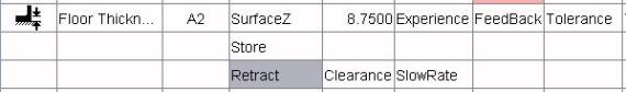
#Approach
There should only be one subroutine containing a comment line with the #Approach keyword, and it will be invoked immediately before each of the cycle routines that measure a feature. For example,
Sub Approach()

  ' #Approach !X !Y !Z Clearance FeedRate

    Z = Z + Clearance

    If (Z < Z.Previous) Then

      Out "<N> G1<X><Y><FeedRate>"

      Out "<N><Z>"

    Else

      Out "<N> G1<Z><FeedRate>"

    Out "<N><X><Y>"

  End If

  Z = Z - Clearance

  GoFeel

End Sub
If you find that there are several parameters that are common to almost all of your cycle subroutines, you may wish to move them to the approach subroutine. Since this is always called before the cycle, you can reduce the number of columns used in the table and provide a more consistent user interface across different cycle types.
#Retract
There should only be one subroutine containing a comment line with the #Retract keyword, and it will be invoked after each of the cycle routines that measure a feature. For example,
Sub Retract()

' #Retract Clearance FeedRate

  Z = Z + Clearance

  Out "<N> G1<Z><FeedRate>"

End Sub
#Cycle
There should as many subroutines containing a comment line with the #Cycle keyword as there are probe cycles available on the target machine. Typically each such subroutine will have numerous parameters, and we suggest listing the mandatory ones before the optional ones. In this example the parameter list is spread across two comment lines, both beginning with the #Cycle keyword.
Sub WallThick()

' #Cycle !X !Y !Width !Depth !Angle

' #Cycle !Correction Offset MaxSafe

  MVAR = 4

  CPA = X

  CPO = Y

  SETVAL = Width

  ID = Depth

  STA1 = Angle

  Out "<N><MVAR><CPA><CPO><SETVAL><ID><STA1>"

  Out "<N><Correction><Offset><MaxSafe>"

  Out "<N> CYCLE979"

End Sub
The alphabetically sorted set of all cycle subroutines is offered in a drop-down list in the fourth column of each feature row of the table.
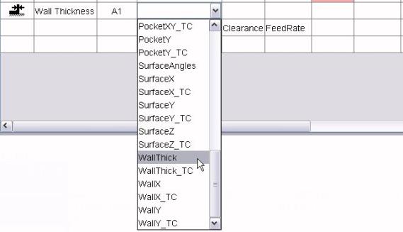
Once a cycle type has been selected, the parameters of the corresponding subroutine will be inserted into the table. Not all of them are included in this illustration.

#Save
Some suites of probe cycles have the ability to save the result of one measurement and compare it with other measurements in a later cycle. For example, if you wanted to check that the Z dimension of one surface matched that of another, you could save the result of probing the first surface, then on the second one use a cycle that compared the new probed Z with the stored value. If your target machine has this capability, you need a single subroutine containing the #Save keyword. For example,
Sub Store()

' #Save

  Out "<N> G65 P9834"

End Sub
The user will then be able to insert a "save" row prior to any retract.
As with any of the keyword identified subroutines, the #Save subroutine can have parameters if needed.
Vericut Composites Programming
When the Write button on VCP's  Post card is triggered, statements and subroutines written in the post-processor language are invoked in a specific sequence. Knowing this sequence is essential to writing or modifying a post. First, all statements that are not in any subroutine are executed, in the order that they appear in the VcPost file. It makes sense to have all these statements at the front of the file. Having them interspersed between subroutines is possible, but would create a maintenance headache. Typically these statements are used to establish the names and types of variables and the properties, such as the output formatting, of registers. The "tree" below shows the sequence in which post subroutines will be invoked. Click on a subroutine name to obtain an alphabetic list of the variables that are defined just prior to that subroutine's call. Once a variable is defined, it remains available for use by all subsequent calls, although its value may be updated.
-
If an initialization subroutine has been requested ...
-
For each tow-packet ...
- LinkHeader
-
If a virtual spin axis is in use ...
-
For each point on the virtual spin axis ...
-
If link has a spinning egress ...
-
If link is from a preceding tow-packet ...
- PulloutHeader
-
For each point in the pullout ...
-
After first point in the pullout ...
- TraverseHeader
-
For each point in the traverse ...
-
For each point or option in the traverse ...
-
If link is from a preceding tow-packet ...
- TraverseTrailer
- RestartHeader
-
If a virtual spin axis is in use ...
-
For each point on the virtual spin axis ...
-
For each point in the restart ...
-
For each point on the restart's lead-in ...
-
If link has a spinning ingress ...
- Extent
-
For each tow present in the tow-packet ...
-
Length (for all the tows)
-
For each add and cut point (not associated with an optional safe restart location) in the packet ...
- Point is appended to a cache which is accessible when needed with the getNthAddCut function, and the numeric variable ACCount is incremented.
-
For each point or option on the head path ...
-
For each mid-packet safe restart point ...
- RestartHeader
-
If a virtual spin axis is in use ...
-
For each point on the virtual spin axis ...
-
For each point in the restart ...
-
For each point on the restart's lead-in ...
-
For the final link ...
- LinkHeader
-
If link has a spinning egress ...
-
For each point or option in the egress ...
-
For each point or option in the traverse ...
-
After first point in the traverse ...
Primer
Called once before all other subroutines if requested on VCP's  Post card. No additional variables defined. Typically a primer subroutine will establish a few variables in the post-processor which will be used subsequently to affect the content of the G-Code file. The following example sets a single variable to adjust the machine's coordinate system;
  ' Sets S value for M38 to 3.

  Sub S3_Vertical()

  ' #Primer

    SForM38 = 3

  End Sub
The comment line immediately following the "Sub" statement is not essential, but very desirable. The "#Primer" line identifies the subroutine as an initialization routine, so that its name can be offered in a drop-down choice list on VCP's Post card.
Modals
Called once at the start of post-processing.
| Variable | Type | Description |
|---|---|---|
| AccDecDist | Number | Acceleration/deceleration distance, between zero and TraverseSpeed. |
| AddAdjustMax | Number | Tow add location adjustment at maximum roller compression. |
| AddAdjustMin | Number | Tow add location adjustment at minimum roller compression. |
| AngleSpacing | Number | Maximum rotation between output points, in degrees. |
| AngleTol | Number | The maximum desirable departure of a tow from the ply direction, in degrees. |
| Compression | Number | Maximum roller compression. |
| CourseSpread | Number | Course spread. |
| CutAdjustMax | Number | Tow cut location adjustment at maximum roller compression. |
| CutAdjustMin | Number | Tow cut location adjustment at minimum roller compression. |
| Directions | Number | 1 for uni-directional, 2 for bi-directional. |
| EgressLength | Number | Length of egress motion. |
| FileName | String | Name of the G-code file. |
| FOff | Number | Off-part feed rate. |
| FOn | Number | On-part feed rate. |
| Header | String | G-Code header line. |
| HeadReverse | Number | Head reversal flag; 0 for slow, 1 for fast. |
| IngressLength | Number | Length of ingress motion. |
| LandOnShelf | Number | Shelf landing flag; 0 for no, 1 for yes. |
| LeadInLen | Number | Desired lead-in length. |
| LimitedEntry | Number | Limited entry/exit flag; 0 for unlimited, 1 for limited. |
| MandrelRPM | Number | Rotisserie revolutions per minute. |
| MatDense | Number | Density of each tow, in g/cu.cm or oz/cu.in. |
| MatThick | Number | Thickness of each tow. |
| MaxGrader | Number | Maximum grader length. |
| MaxTraverse | Number | Maximum on-form traverse. |
| MinGapLen | Number | Minimum permissible gap in any tow. |
| MinGrader | Number | Minimum grader length. |
| MinSteering | Number | Minimum desirable tow steering radius. |
| MinTowLen | Number | Minimum permissible tow length. |
| Natural | Number | Path geometry flag; 0 for rosette rule, 1 for natural, 2 for limited steer, 3 for parallel, 4 for geodesic. |
| NominalPress | Number | Nominal roller compression. |
| Numbering | Number | Tow numbering flag; 0 for left-to-right, 1 for right-to-left. |
| OffSpacing | Number | Maximum distance between off-part output points. |
| OnSpacing | Number | Maximum distance between on-part output points. |
| Part | String | Name of the CAD file (CATPart). |
| PlyAngle | Number | Ply angle, in degrees. |
| PlyIdent | String | Ply identifier. |
| PlyNumber | Number | Ply number. |
| Post | String | Name of the VcPost file. |
| Product | String | Software product's name, "VCP". |
| RetractDist | Number | Retract distance. |
| RollerAction | Number | Roller action flag; 0 for "press", 1 for "wrap". |
| RollerClear | Number | Roller clearance. |
| RollOffset | Number | Offset of roll center from head path. |
| Rotisserie | Number | Rotisserie flag; -1 if none, 0 for stationary, 1 for spinning. |
| RunOutLen | Number | Desired run-out length. |
| ScrewHand | Number | Screw direction; -1 for left-hand, 0 for none, +1 for right-hand. |
| SeqIdent | String | Sequence identifier. |
| SeqNumber | Number | Sequence number. |
| ShelfAngle | Number | Shelf approach angle, in degrees. |
| ShelfInset | Number | Shelf boundary inset. |
| SpinAxis | Number | Rotisserie axis; 0 for X, 1 for Y, 2 for Z. |
| SpiralAngle | Number | Angular extent of limited entry or exit, in degrees. |
| SpliceLen | Number | Desired tow splice length. |
| SpliceSpace | Number | Minimum permissible distance between tow splices. |
| Stamp | String | Time stamp for the G-code file's creation. |
| StartX | Number | X coordinate of ply's start point. |
| StartY | Number | Y coordinate of ply's start point. |
| StartZ | Number | Z coordinate of ply's start point. |
| Thumb | String | Name of JPEG thumbnail file. |
| TowCount | Number | Number of tows on the machine's head. |
| TowEdgeLap | Number | Distance that each tow should overlap the ply boundaries. |
| TowReduction | Number | Number of tows to reduce by when trying to comply with maximum roller compression. |
| TowTowLap | Number | Maximum permissible overlap of adjacent tows. |
| TowWidth | Number | Width of each tow. |
| TraverseSpeed | Number | Maximum traverse velocity, in mm/min or in/min, parallel to spin axis. |
| UnitPerMm | Number | Linear output unit per millimeter (1.0 or 1.0/25.4). |
| User | String | User's computer account name. |
| Version | String | Software product's version number. |
| VirtualAxis | Number | Virtual spin axis flag; 0 for none, 1 for automatically determined virtual axis. |
Extent
Called once after the Modals subroutine to define the physical extent of all linked tow-packets in the ply, it will subsequently be invoked for each individual packet. If there is a stationary or spinning rotisserie, the variables are all defined in the axis system specified on VCP's  Links card. If there is no rotisserie, the variables are all defined in the same axis system as the other coordinates in the G-Code file.
| Variable | Type | Description |
|---|---|---|
| AMax | Number | Maximum normal angle about the spin axis, in degrees. |
| AMin | Number | Minimum normal angle about the spin axis, in degrees. |
| RMax | Number | Maximum radius from the real spin axis. |
| Rotation | Number | -1 if the tow-packet requires clockwise rotisserie motion, 0 if there is no rotisserie, or there is one and it is stationary, +1 if the tow-packet requires counter-clockwise rotisserie motion. |
| TowWidth | Number | Width of each tow in this packet. |
| XMax | Number | Maximum X coordinate. |
| XMin | Number | Minimum X coordinate. |
| YMax | Number | Maximum Y coordinate. |
| YMin | Number | Minimum Y coordinate. |
| ZMax | Number | Maximum Z coordinate. |
| ZMin | Number | Minimum Z coordinate. |
Length
Invoked after the initial Extent call, first in a loop for each tow number present in the linked tow-packets, then again for the total amount of material required. This same pattern of a loop and a single call is used subsequently as each tow-packet is processed. Tow areas can be combined with the material thickness (MatThick) and material density (MatDense) values already established, to present volumes and weights.
| Variable | Type | Description |
|---|---|---|
| TowArea | Register | Tow area. |
| TowLen | Register | Tow length. |
| TowNum | Register | Tow number, or zero for all tows combined. |
CamHeader
Invoked once after the initial Length call if there is a virtual spin axis involved. No additional variables defined.
CamPoint
Invoked once for each point on the virtual spin axis.
| Variable | Type | Description |
|---|---|---|
| RMax | Number | Maximum radius from the real spin axis. |
| X | Register | X of point on virtual spin axis. |
| Y | Register | Y of point on virtual spin axis. |
| Z | Register | Z of point on virtual spin axis. |
CamTrailer
Invoked once after all the CamPoint calls. No additional variables defined.
PlyHeader
Invoked once after the initial Length calls, or the CamTrailer call. No additional variables defined.
LinkHeader
Called to start processing of the ply's initial entry, for each link between tow-packets, and for the final retract.
| Variable | Type | Description |
|---|---|---|
| LinkType | Number | -1 or initial entry, 0 for link, +1 for final exit |
| Rotation | Number | -1 if the tow-packet that follows requires clockwise rotisserie motion, 0 if there is no rotisserie, there is one and it is stationary, or this link is a final exit, +1 if the tow-packet that follows requires counter-clockwise rotisserie motion. |
| TowWidth | Number | Width of each tow in the following tow-packet, if there is one. |
PulloutHeader
Called to start the processing of an optional safe pullout block. No additional variables defined. This function should be omitted from any post that is not intended to handle safe pullouts.
PulloutTrailer
Called after the processing of an optional safe pullout block. No additional variables defined.
MoveTo
Called for each point on a link's head path. The coordinate system for the variables is the one specified on VCP's Post card.
| Variable | Type | Description |
|---|---|---|
| DTwist | Number | Counter-clockwise rotation of (DX,DY,DZ) vector about surface normal, in degrees. |
| DX | Number | X component of unit vector in direction of motion. Sequence of (DX,DY,DZ) vectors provide shorter of two possible head rotations. |
| DY | Number | Y component of unit vector in direction of motion. |
| DZ | Number | Z component of unit vector in direction of motion. |
| ETwist | Number | Counter-clockwise rotation of (EX,EY,EZ) vector about surface normal, in degrees. |
| EX | Number | X component of unit vector in alternate direction. Sequence of (EX,EY,EZ) vectors provide longer of two possible head rotations. |
| EY | Number | Y component of unit vector in alternate direction. |
| EZ | Number | Z component of unit vector in alternate direction. |
| I | Number | X component of unit outward surface normal vector. |
| J | Number | Y component of unit outward surface normal vector. |
| K | Number | Z component of unit outward surface normal vector. |
| ToLeadIn | Number | Distance to start of lead-in. Negative if no lead-in (pull-out). |
| VirtDX | Number | X component of offset from rotisserie's spin axis to virtual spin axis. Will be zero if there is no rotisserie, if it is not spinning in one direction, or if the virtual spin axis capability has not been turned on. |
| VirtDY | Number | Y component of offset from rotisserie's spin axis to virtual spin axis. Will be zero if there is no rotisserie, if it is not spinning in one direction, or if the virtual spin axis capability has not been turned on. |
| VirtDZ | Number | Z component of offset from rotisserie's spin axis to virtual spin axis. Will be zero if there is no rotisserie, if it is not spinning in one direction, or if the virtual spin axis capability has not been turned on. |
| X | Register | X of mid-roller point closest to form. |
| Y | Register | Y of mid-roller point closest to form. |
| Z | Register | Z of mid-roller point closest to form. |
OffForm
Invoked when the roller moves out of range of the form. No additional variables defined. Can be used to turn on collision checking between the roller and the form, and to turn off roller direction checking in verification software, such as VCS.
OnForm
Invoked when the roller moves within range of the form. No additional variables defined. Can be used to relax collision checking between the roller and the form, allowing for roller compression and to turn on roller direction checking in verification software, such as VCS.
TraverseHeader
Called to start processing of the off-part traverse portion of a link. This function should be omitted from any post that does not need to handle "wind-up" problems in a head's "wrist action".
TraverseTo
Called for each point in the traverse portion of a link's head path, provided TraverseHeader routine is present. This data should not be output directly to the G-Code file, as it will be repeated in MoveTo calls. Instead it can be used to determine whether the sequence of direction vectors passed in (DX,DY,DZ) or (EX,EY,EZ) is better suited to avoiding head "wind-up".
| Variable | Type | Description |
|---|---|---|
| DTwist | Number | Counter-clockwise rotation of (DX,DY,DZ) vector about surface normal, in degrees. |
| DX | Number | X component of unit vector in direction of motion. Sequence of (DX,DY,DZ) vectors provide shorter of two possible head rotations. |
| DY | Number | Y component of unit vector in direction of motion. |
| DZ | Number | Z component of unit vector in direction of motion. |
| ETwist | Number | Counter-clockwise rotation of (EX,EY,EZ) vector about surface normal, in degrees. |
| EX | Number | X component of unit vector in alternate direction. Sequence of (EX,EY,EZ) vectors provide longer of two possible head rotations. |
| EY | Number | Y component of unit vector in alternate direction. |
| EZ | Number | Z component of unit vector in alternate direction. |
| I | Number | X component of unit outward surface normal vector. |
| J | Number | Y component of unit outward surface normal vector. |
| K | Number | Z component of unit outward surface normal vector. |
| VirtDX | Number | X component of offset from rotisserie's spin axis to virtual spin axis. Will be zero if there is no rotisserie, if it is not spinning in one direction, or if the virtual spin axis capability has not been turned on. |
| VirtDY | Number | Y component of offset from rotisserie's spin axis to virtual spin axis. Will be zero if there is no rotisserie, if it is not spinning in one direction, or if the virtual spin axis capability has not been turned on. |
| VirtDZ | Number | Z component of offset from rotisserie's spin axis to virtual spin axis. Will be zero if there is no rotisserie, if it is not spinning in one direction, or if the virtual spin axis capability has not been turned on. |
| X | Register | X of mid-roller point closest to form. |
| Y | Register | Y of mid-roller point closest to form. |
| Z | Register | Z of mid-roller point closest to form. |
TraverseTrailer
Called after processing the off-part traverse portion of a link. No additional variables defined.
LinkTrailer
Called after processing each link, including the ply's initial entry and final retract. No additional variables defined.
PacketHeader
Called to start processing of a tow-packet. No additional variables defined.
RestartHeader
Called to start processing of an optional safe restart block. No additional variables defined. This function should be omitted from any post that is not intended to handle safe restarts.
RestartBuffer
Called to permit buffering of the safe restart's extra add point and any of the original add and cut points that occur after the safe restart location. The original add and cut points are still accessible using the getNthAddCut function. The details of the new add point is pre-loaded into the following variables. The coordinate system for the variables is the one specified on VCP's Post card.
| Variable | Type | Description |
|---|---|---|
| AddCutA | String | Binary string representation of the tow on/off state. For a 16 tow head an example would be "0001111111111100". |
| AddCutB | String | Reversed binary string representation of the tow on/off state. For the same example, it would be "0011111111111000". The lowest order bit, on the right end of the string, corresponds to the tow on the right side of the head, when "sitting" on top of the head and looking in the direction of motion. |
| AddCutI | Number | Number whose binary representation encapsulates the tow on/off state. For the same example, the value would be 8188. |
| AddCutJ | Number | Number whose reversed binary representation encapsulates the tow on/off state. For the same example, the value would be 16376. The lowest order bit in this value, corresponds to the tow on the right side of the head, when "sitting" on top of the head and looking in the direction of motion. |
| DX | Number | X component of unit vector in direction of motion. |
| DY | Number | Y component of unit vector in direction of motion. |
| DZ | Number | Z component of unit vector in direction of motion. |
| I | Number | X component of unit outward surface normal vector. |
| J | Number | Y component of unit outward surface normal vector. |
| K | Number | Z component of unit outward surface normal vector. |
| LParam | Number | Good approximation of the distance of point along the head path from start of tow-packet's original lead-in. Increases monotonically in the direction of lay. |
| SumThick | Number | Thickness of material in prior layers at this point, provided the variable NeedThickness is defined and non-zero. |
| VirtDX | Number | X component of offset from rotisserie's spin axis to virtual spin axis. Will be zero if there is no rotisserie, if it is not spinning in one direction, or if the virtual spin axis capability has not been turned on. |
| VirtDY | Number | Y component of offset from rotisserie's spin axis to virtual spin axis. Will be zero if there is no rotisserie, if it is not spinning in one direction, or if the virtual spin axis capability has not been turned on. |
| VirtDZ | Number | Z component of offset from rotisserie's spin axis to virtual spin axis. Will be zero if there is no rotisserie, if it is not spinning in one direction, or if the virtual spin axis capability has not been turned on. |
| X | Register | X of mid-roller contact point on form. |
| Y | Register | Y of mid-roller contact point on form. |
| Z | Register | Z of mid-roller contact point on form. |
RestartTrailer
Called after processing of an optional safe restart block. No additional variables defined.
GoTo
Called for each point on a tow-packet's head path. The coordinate system for the variables is the one specified on VCP's Post card.
| Variable | Type | Description |
|---|---|---|
| AddCutA | String | Binary string representation of the tow on/off state. For a 16 tow head an example would be "0001111111111100". The lowest order bit, on the right end of the string, corresponds to the tow on the left side of the head, when "sitting" on top of the head and looking in the direction of motion. |
| AddCutB | String | Reversed binary string representation of the tow on/off state. For the same example, it would be "0011111111111000". The lowest order bit, on the right end of the string, corresponds to the tow on the right side of the head, when "sitting" on top of the head and looking in the direction of motion. |
| AddCutI | Number | Number whose binary representation encapsulates the tow on/off state. For the same example, the value would be 8188. The lowest order bit in this value, corresponds to the tow on the left side of the head, when "sitting" on top of the head and looking in the direction of motion. |
| AddCutJ | Number | Number whose reversed binary representation encapsulates the tow on/off state. For the same example, the value would be 16376. The lowest order bit in this value, corresponds to the tow on the right side of the head, when "sitting" on top of the head and looking in the direction of motion. |
| Cached | Number | Cache flag; 1 if point was placed in the cache, and is thus an add or cut point, 0 otherwise. |
| DTwist | Number | Counter-clockwise rotation of (DX,DY,DZ) vector about surface normal, in degrees. |
| DX | Number | X component of unit vector in direction of motion. |
| DY | Number | Y component of unit vector in direction of motion. |
| DZ | Number | Z component of unit vector in direction of motion. |
| I | Number | X component of unit outward surface normal vector. |
| J | Number | Y component of unit outward surface normal vector. |
| K | Number | Z component of unit outward surface normal vector. |
| LParam | Number | Good approximation of the distance of point along the head path from start of tow-packet's original lead-in. Increases monotonically in the direction of lay. |
| SumThick | Number | Thickness of material in prior layers at this point, provided the variable NeedThickness is defined and non-zero. |
| ToLastCut | Number | Distance to last cut (start of run-out). Negative if last cut already passed. |
| ToNextAdd | Number | Distance to the next add. Negative if last add already passed. |
| ToNextCut | Number | Distance to the next cut. Negative if last cut already passed. |
| ToRunOut | Number | Distance to end of run-out. |
| TowsInPacket | Number | Number of tows in the current tow-packet. |
| VirtDX | Number | X component of offset from rotisserie's spin axis to virtual spin axis. Will be zero if there is no rotisserie, if it is not spinning in one direction, or if the virtual spin axis capability has not been turned on. |
| VirtDY | Number | Y component of offset from rotisserie's spin axis to virtual spin axis. Will be zero if there is no rotisserie, if it is not spinning in one direction, or if the virtual spin axis capability has not been turned on. |
| VirtDZ | Number | Z component of offset from rotisserie's spin axis to virtual spin axis. Will be zero if there is no rotisserie, if it is not spinning in one direction, or if the virtual spin axis capability has not been turned on. |
| X | Register | X of mid-roller contact point on form. |
| Y | Register | Y of mid-roller contact point on form. |
| Z | Register | Z of mid-roller contact point on form. |
| Function | Type | Description |
|---|---|---|
| getNthLength1 | Number | Length of the next tow segment to be cut, for the given tow number (0 <= tow number < TowsInPacket). |
| getNthLength2 | Number | Distance to next tow add, for the given tow number (0 <= tow number < TowsInPacket). |
| getNthLength3 | Number | Distance to next tow cut, for the given tow number (0 <= tow number < TowsInPacket). |
Option
A post-processor option's subroutine is invoked when the option is encountered on a link or tow-packet. Only those parameters which were specified as being relevant to the option are set prior to the subroutine call. Prior values of other parameters are not altered.
| Variable | Type | Description |
|---|---|---|
| OptNumber1 | Number | 1st optional numeric parameter. |
| OptNumber2 | Number | 2nd optional numeric parameter. |
| OptNumber3 | Number | 3rd optional numeric parameter. |
| OptNumber4 | Number | 4th optional numeric parameter. |
| OptString1 | String | 1st optional string parameter. |
| OptString2 | String | 2nd optional string parameter. |
| OptSwitch1 | Number | 1st optional Boolean parameter (0 for "Off", 1 for "On"). |
| OptSwitch2 | Number | 2nd optional Boolean parameter (0 for "Off", 1 for "On"). |
An example may help clarify the relationship between a post-processor option, the subroutine it needs in the VcPost file, and the parameters in the table above. Suppose we need to insert messages to the operator in the G-Code file. We will call this option "OpMessage" and the content of the parameter fields on VCP's Options card may look like this;
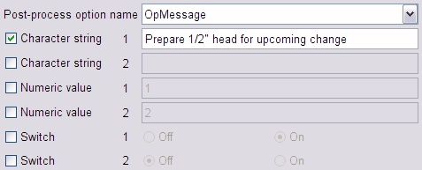
We need a subroutine called "OpMessage", which only expects the first string parameter to be defined. It could be as simple as;
  Sub OpMessage()

  ' #Option

  ' #C1 Operator message

    Out "<N>(" & OptString1 & ")"

  End Sub
The comment lines immediately following the "Sub" statement are not essential, but very desirable. The "#Option" line identifies the subroutine as an option, so that its name can be offered in a drop-down choice list on VCP'sOptions card. The "#C1" line provides text to describe the meaning of the first character string parameter. This text gets shown as a "tip" for the corresponding input field. "#C2", if present, would be for the second character string. "#N1" and "#N2" serve the same purpose for the two numeric values, and "#S1" and "#S2" are for the switches.
PacketTrailer
Called after processing of a tow-packet. No additional variables defined.
PlyTrailer
Called once at the end of post-processing. No additional variables defined.
Vericut Composites Probing
A post-processor written for Vericut Composites probing uses the same BASIC-like language as a post-processor which generates programs for Vericut Composites material laying. But it is strongly recommended that you use separate post-processors for these two functions, even for the same machine.
The subroutines and the order in which they are invoked when a user clicks on the second Write button on VCP's  Probe card, are very different. The "tree" below shows the sequence in which post subroutines will be invoked. Click on a subroutine name to obtain an alphabetic list of the variables that are defined just prior to that subroutine's call. Once a variable is defined, it remains available for use by all subsequent calls, although its value may be updated. The list of reserved variable names for a Vericut Composites probing post-processor is the same as the list for a Vericut Composites material laying post-processor.
- Modals
- ProgramHeader
-
For each probe point ...
Post-Processor Subroutines/Variables
Modals
Called once at the start of post-processing.
| Variable | Type | Description |
|---|---|---|
| FileName | String | Name of the G-code file. |
| Header | String | G-Code header line. |
| Part | String | Name of the CAD file (CATPart). |
| Post | String | Name of the VcPost file. |
| Product | String | Software product's name, "VCP". |
| Stamp | String | Time stamp for the G-code file's creation. |
| UnitPerMm | Number | Linear output unit per millimeter (1.0 or 1.0/25.4). |
| User | String | User's computer account name. |
| Version | String | Software product's version number. |
ProgramHeader
Invoked once after the Modals call. No additional variables defined.
SetAngle
Called just prior to positioning to each probe point.
| Variable | Type | Description |
|---|---|---|
| Rotisserie | Number | Required rotisserie angle, in degrees. |
MoveTo
Called for each probe point. The coordinate system for the variables is the one specified on VCP's  Probe card.
| Variable | Type | Description |
|---|---|---|
| I | Number | X component of unit outward vector, if supplied. |
| J | Number | Y component of unit outward vector, if supplied. |
| K | Number | Z component of unit outward vector, if supplied. |
| X | Register | X of probe point. |
| Y | Register | Y of probe point. |
| Z | Register | Z of probe point. |
Probe
Called just after positioning to each probe point.
| Variable | Type | Description |
|---|---|---|
| OptNumber1 | Number | Numeric parameter. |
You should have at least as many of these subroutines as there are different probe macros available. The simplest example subroutine is one which does nothing. It would be used at intermediate points between probed features, and may look like this;
Sub Position()
' #Probe
End Sub
The comment line immediately following the "Sub" statement is not essential, but very desirable. The "#Probe" keyword identifies the subroutine as potentially being associated with a probe point, so that its name can be offered in drop-down choice lists within the Probe point table on VCP's  Probe card.
ProgramTrailer
Invoked once after all the probe points have been processed. No additional variables defined.