Vericut File Descriptions
The types of files used by Vericut to load and save various types of data are listed below in alphabetical order. See the appropriate section for a description of file contents and formats, and how to open and save them.
ACIS Model File
Typical file extension: .sat
An ACIS model file is model file created using the 3D ACIS Modeler (ACIS) owned by Spatial Corporation (formerly Spatial Technology). An ACIS model file is an ASCII text file.
Use of these files in Vericut requires an ACIS Model Interface license, and the installation of the CAD Model Interface files (aka the \"Spatial Technologies\" libraries).
See the Vericut website for additional information on the ACIS Model Interface.
Also see Installing the Model Interface Modules in the Installing Vericut Products section of the Vericut Help Library.
APT Output File
Typical file extension: .apt
An ASCII text file containing APT NC program records resulting from reverse post-processing by Vericut. By default when sequenced G-Code data is converted, columns 73-80 in the output file indicate the block numbers of the G-Code data block where the converted records came from.
Sequence number output is controlled via the Output Block Sequence Numbers feature in the Messages section of the Settings window, G-Code Outputs tab.
Apt Output Files are created and viewed via the Settings window, G-Code Outputs tab APT Output File features (Project tab > Settings).
Click here to see a sample input G-Code NC Program file.
Click here to see a sample of the resulting APT Output file.
APT Table File
Typical file extension: .tbl
An ASCII text file used by the Binary CL Converter that contains information necessary to convert binary APT data into ASCII APT NC program records. Such information includes: blocking factor, major and minor word classes, sub-classes, etc.
APT Table files are loaded into Vericut via the Utilities tab > Binary CL function. APT Table files can also be specified on the command line when the Binary CL Converter is executed, such as during batch processing to simulate NC programs without user interaction.
Click here to see a sample APT Table File
The sample APT Table file above, "aptwords.tbl", is located in the \vericut folder of your Vericut installation.
💡 Tips:
- The default blocking factor for interpreting binary CL data is 3228. If this does not produce favorable results, use any text editor to change the blocking factor. Other typical blocking factors you can try are: 512, 4628, 15476.
- If the ASCII NC program file output by the converter has major or minor words other than what you expected, try editing the APT Table file to change the "Word" output for a specific APT class/subclass.
Assembly Library File
The new assembly library file allows you to store assemblies in a library.
An assembly is made up of components. They can be machine and/or attach components.
New options have been added to the component branch right mouse shortcut menu and configure component menu to import and export assemblies from the library.
Batch Script Files
Multiple Vericut batch sessions can be run via a single executable command by including Vericut batch commands in an executable script file. The script file is then submitted to the operating system for processing. After each batch execution terminates, the operating system then executes the next command in the script file.
Batch files for different operating systems differ slightly in format. Details will follow later in this document. In general, each batch command in the script file appears as it would when entered by itself on the command line. Other operating system commands, such as those that delete or rename files can also be included in the script file.
💡 Tip: Vericut batch files can be easily created using Vericut's Batch Wizard.
Windows batch script files
A batch file to be run on Windows is named with a ".bat" extension, for example "batchfile.bat". Windows NT batch execution lines in the script file are "called" via the "call" command to return control to the script file after each Vericut execution. The examples that follow show two sample script files.
Windows XP batch script file examples:
Example 1 executes two batch sessions, each processing a part unrelated to the other.
call vericut batch "vcp=part1.VcProject"
call vericut batch "vcp=part2.VcProject"
Example 2 represents a part machined in two setups: the first is configured to automatically save an In-process file named "setup1.ai" via the AutoSave function. The second uses the ip=
call vericut batch "vcp=setup1.VcProject"
call vericut batch "vcp=setup2.VcProject" "ip=setup1.ai"
CATIA V5 Model File
Typical file extension: .CATPart
A CATIA V5 file is a binary file created using CATIA V5 (requires CATIA V5 version R21 with at least Vericut 7.4 or later). Use of these files in Vericut requires a CATIA V5 Model Interface license, and the installation of the CAD Model Interface files (aka the \"Spatial Technologies\" libraries).
See the Vericut website for additional information on the CATIA V5 Model Interface.
Also see Installing the Model Interface Modules in the Installing Vericut Products section of the Vericut Help Library.
Control File
Typical file extensions: .ctl, .xctl
A Control File is an XML (Extensible Markup Language) text file that contains data describing how the NC control processes G-Codes. Data in this file includes: a list of interpretable machine codes, machine code format information, rules for grouping machine codes, and rules for calling macros. This file is required to interpret G-Code data via the G-Code Data NC program type. When the C Macro Extension – Application Programming Interface or CME–API (ref. CME-API in the Vericut Development Tools section, in the Vericut Help Library) is used to create a custom CME file, the Control file can also specify a custom CME file to assist with the simulation.
By default, Vericut is configured with a "Fanuc" control. Many control configurations are available in the library that is installed with Vericut software. See Library Control Files section of Vericut Help for more information.
A different Control file can be loaded by right clicking on a Control branch in the Project Tree and selecting Open from the menu that displays. Use the Open Control window (ref. Open Control window in the Project Tree section of Vericut Help) that displays to select the desired Control file.
NC control configurations are changed via the "Control" options in the Machine/Control tab in the Vericut menu ribbon. Use Machine/Control tab > Save As (Control) to save the new file.
The following user and version related information is also saved in the project file:
Encrypted Control Files
A "standard" encrypted (X-File) control file:
-
has a .xctl extension
-
works with a standard Vericut license.
- is a compressed binary file.
- contains all files referenced by the Control file (no external subroutines).
- simulates exactly the same as a standard control file (.ctl)
- disables the Configuration tab features when used in a setup.
- can be created by any user.
- cannot be decrypted/expanded except by Vericut so retain your original control (.ctl) file
A "limited" encrypted (X-File) control file:
-
has a .xctl extension
-
works only for a specific customer with a Vericut Single Platform license.
- is a compressed binary file.
- contains all files referenced by the Control file (no external subroutines).
- disables the Configuration tab features when used in a setup.
- can only be created by Vericut.
- cannot be decrypted/expanded except by Vericut.
Click here to see a sample Control File.
The sample control file, "hei530.ctl", is located in the /library/ folder of your Vericut installation.
Control Report File
Typical file extension: .rpt
A Control Report File is an ASCII text file that contains information about how the current NC control configuration will interpret various codes. Reported information includes:
G-Codes present in the NC program and macros (actions) the control will perform, variables used (if any), cutting tools used, subroutines defined and referenced, and more.
Control Report files are created via the Settings window, G-Code Outputs tabControl Report features (Project tab > Settings).
Click here to see a sample Control Report File
CSYS File
A CSYS File is an ASCII text file containing information necessary to create a Vericut Coordinate System using the CSYS from File feature in the Configure Coordinate System menu (ref. Configure Coordinate System menu in the Project Tree section of Vericut Help). The file contains a collection of APT CL matrices, possibly with different syntaxes in a single file. The CSYS File is also used by the csys_file command line argument.
The CSYS file may contain one or all combinations of:
CATIA syntax
See the comments in the NC program file for vcmatrix_catia.VcProject, located in the /samples/APT_CL/ folder of your Vericut installation for examples.
NX syntax
See the comments in the NC program file for vcmatrix_ug.VcProject, located in the /samples/APT_CL/ folder of your Vericut installation for examples.
PTC syntax
See the comments in the NC program file for vcmatrix_ptc.VcProject, located in the /samples/APT_CL/ folder of your Vericut installation for examples.
APT Matrix and Vericut Matrix
See the comments in the NC program file for vcmatrix_pprint.VcProject, located in the /samples/APT_CL/ folder of your Vericut installation for examples.
Design Locations File
Typical file extension: .xml
A Design Locations File is an XML (Extensible Markup Language) text file containing location data, hole characteristics, fastener characteristics, stack counts and stack thickness, etc.
A Design Locations File is created using Vericut Drill and Fastener Programming. A customized script required to generate a Design Locations File out of a CAD system.
A Design Locations File is post-processed for a specific automated drill and fastener machine tool to create a G-Code NC program for use in Vericut Drill and Fastener Simulation and to drive the drilling and fastening machine.
In Vericut Drill and Fastener Simulation, AUTO-DIFF compares the data collected during the simulation to the Design Location File to ensure that the result of using the NC program on the machine will match the "design" criteria.
Click here to see a sample Design Locations File
G-Code Log File
Typical file extension: .log
A G-Code Log File is an ASCII text file that contains error, warning and informational messages about G-Code processing. One of the most valuable pieces of information this file provides is a copy of each input G-Code data block followed by the converted ASCII APT NC program records indented by 6 spaces. This allows you to see a direct translation of G-Code versus equivalent ASCII APT output for all NC program records processed.
G-Code LogFiles are created and viewed via the Settings window, G-Code Outputs tabG-Code Log File features (Project tab > Settings).
For help with interpreting error and warning messages in this file, contact Vericut technical support via our website, just click on the support link.
Click here to see a sample G-Code Log File
G-Code Report File
Typical file extension: .rpt
A G-Code Report File is an ASCII text file that contains information about how the current NC control configuration will interpret a G-Code NC program file. Reported information includes: G-Codes present in the NC program and macros (actions) the control will perform, variables used (if any), cutting tools used, subroutines defined and referenced, and more. G-Code Report files are created via the Report tab > View G-Code Report function.
Click here to see a sample G-Code Report File
IGES Model File
Typical file extension: .igs
An IGES (Initial Graphics Exchange Specification) model file, also known as an "IGES file", is an ASCII text file which describes virtually anything that can be modeled in a CAD system. IGES data is widely accepted as an industry standard for transferring model data. While IGES model files containing only 2-D data (lines and arcs) are not useful in Vericut, files containing 3-D surfaces and solids can be used to describe stock, fixture, or design models, as well as machine component shapes.
IGES model files are loaded via the Configure Model menu: Model tab (ref. Configure Model menu, Model tab in the Project Tree section of Vericut Help) or can be converted into STL or Vericut Polygon model files using the IGES converter.
Initialization File
An Initialization File is a text, or subroutine, file used to initialize various types of variables used during simulation processing. An Initialization File is processed at the same time as the "Start of Processing" event.
Vericut supports three types of initialization files: Setup Initialization Files, Machine Initialization Files, and Control Initialization Files. Each of these types is described below.
Setup Initialization Files
Setup Initialization Files are used to initialize variables used in setups. Setup Initialization Files are specified using the Initialization File feature found in the Project Tree, Configure Setup menu: G-Code tab. See Configure Setup menu: G-Code tab in the Project Tree section of Vericut Help for information on using this feature.
Machine Initialization Files
Machine Initialization Files are used to initialize variables used by the NC machine. Machine Initialization Files are specified using the Initialization File feature found on the Machine Settings window. See Machine Settings window in the Machine/Control tab section of Vericut Help for information on using this feature.
Control Initialization Files
Control Initialization Files are used to initialize variables used in the NC control. Control Initialization Files are specified using the Initialization File feature found on the Control Settings window: General tab. See Control Settings window: General tab in the Machine/Control tab section of Vericut Help for information on using this feature.
The variables initialized using the Initialization Files can be viewed and monitored in the Variables panel. See Variables panel in the Project Tree section of Vericut Help for additional information.
Using Multiple Initialization Files
Vericut only supports specifying one Initialization File of each type. Since an Initialization File works just like a subroutine file, if you want to pass information in multiple Initialization Files of a particular type through to Vericut, create a "master" Initialization File that calls the all of the other Initialization Files that you want to use. Then point the Initialization File feature for the particular type at the "master" Initialization File.
Example
The file names used below are arbitrary.
-
Create "Machine_Initialization_ File1" and set it up to initialize the desired variables. Create "Machine_Initialization_ File2" and set it up to initialize the desired variables. Repeat as necessary to create all of the Machine Initialization sub-files.
-
Create a "Master_Machine_Initialization_File" and set it up to call Machine_Initialization_ File1, Machine_Initialization_ File2, Machine_Initialization_ File3, ...
- In the Machine Settings window, point the Initialization File feature at "Master_Machine_Initialization_File".
Initialization Files and Multiple Channel Sync Jobs
For Sync jobs with multiple channels, the Initialization Files do not get run multiple times. The Initialization File will set the variables to the sub-system associated with the first channel.
If you want to set variables for more than one channel, create a "master" Initialization File. Set it up to call the "ChangeSubsystemID" macro with the name of the first sub-system (channel) name as the argument and then call the initialization sub-file that you want to use to initialize the variables for the first sub-system (channel). Repeat the macro call/initialization sub-file sequence for each additional sub-system (channel). Finish with a final call to the "ChangeSubsystemID" macro with the name of the first sub-system (channel 1) name as the argument so that simulation will work correctly.
Point the Initialization File feature at the "master" Initialization File.
Using Initialization Files when the same Variable Names, with different values, are used for different sub-systems
When the same Variable Names, with different values, are used for different sub-systems, create a "master" Initialization File. Set it up to call the "ChangeSubsystemID" macro with the name of the first sub-system name as the argument and then call the initialization sub-file that that contains the values for the first sub-system. Repeat the macro call/initialization sub-file sequence for each additional sub-system.
Point the Initialization File feature at the "master" Initialization File.
In-Process File
Typical file extension: .ip
A part ASCII text-part binary file also known as an "IP file" that contains the data necessary to re-establish a Vericut session, including the current Vericut model (with cuts), user interface settings, and a copy of the Log file. IP files are also used to "backup" the verification session, safeguarding against lost work if the session is interrupted by computer or power failure.
You can save an In-process file interactively via File tab > Save As (In-Process), or automatically via the Project tab > Settings > AutoSave tab function. You can also save an IP file using the SAVE_IP, Vericut-COMMAND record (ref. to Vericut-COMMAND Record in Automating Vericut, in the Vericut Help Library). Due to differences in math processing on various computer types, IP files are usable on computers of the same type on which they were saved.
In-Process (IP) files are by default compressed when they are saved. Vericut can read these compressed files directly.
To disable writing compressed IP files, set the environment variable CGTECH_COMPRESS=IP (ref. Environment Variables section of Vericut Help for additional information).
Load IP files via File tab > Open In-Process to re-establish a Vericut session or provide a Vericut model for additional machining and analysis. IP files can also be specified on the command line when Vericut is executed, such as during batch processing to simulate NC programs without user interaction.
📝 NOTE: Environment variables can be used to affect Vericut's use of IP files. For more information, see Environment Variables section of Vericut Help.
Log File
Typical file extension: .log
The Vericut LOG FILE is an ASCII text file that contains information about a Vericut session, such as: names of NC programs processed, errors, warnings, simulated machining times, and other informational messages.
When Vericut is run, it must always be able to open a Log file. When an existing Log file of the same name is found Vericut responds differently, depending on the run mode:
Vericut run in interactive mode — Log file is automatically reset, unless the "append log" command line option is used.
Vericut run in batch mode — Log file is automatically reset, unless the "reset log" command line option is used.
For more information on command line options used with Vericut, see Command line options for Vericut in the Automating Vericut section in the Vericut Help Library.
Using the Info tab > Vericut Log function, Log file contents can be viewed, edited, or the file name changed. For help with interpreting error and warning messages in this file, contact Vericut technical support via our website, just click on the support link.
Click here to see a sample Vericut Log file.
📝 NOTE: In the Vericut Logfile "Cutter Stick Out" column of the Tool Summary Table, in cases where no holder has been defined, or in the case of an APT tool, the "Cutter Stick Out" column will display the length of the cutter instead of the Cutter Stick Out value.
Machine File
Typical file extensions: .mch, .xmch
A Machine File is an XML (Extensible Markup Language) text file that contains data describing the construction, kinematics, and other properties of an NC machine tool. By default, Vericut is configured with a 3-axis vertical mill machine. Many machine configurations are available in the library that is installed with Vericut software. See Library Machine Files section for more information.
A different Machine file can be loaded into Vericut by right clicking on a Machine branch in the Project Tree and selecting Open from the menu that displays. Use the Open Machine window (ref. Open Machine window in the Project Tree section of Vericut Help) that displays to select the desired Machine file.
NC machine configurations are changed via the "Machine Settings window" options in the Machine/Control tab. You can save the new file via Machine/Control tab > Save As (Machine).
The following user and version related information is also saved in the project file:
Encrypted Machine Files
A "standard" encrypted (X-File) machine file:
-
has a .xmch extension
-
works with a standard Vericut license.
- is a compressed binary file.
- contains all files referenced by the Machine file (no external models).
- simulates exactly the same as a standard machine file (.mch)
- disables the Configuration tab features when used in a setup.
- can be created by any user.
- cannot be decrypted/expanded except by Vericut so retain your original machine (.mch) file
A "limited" encrypted (X-File) machine file:
-
has a .xmch extension
-
works only for a specific customer with a Vericut Single Platform license.
- is a compressed binary file.
- contains all files referenced by the Machine file (no external models).
- disables the Configuration tab features when used in a setup.
- can only be created by Vericut.
- cannot be decrypted/expanded except by Vericut.
Click here to see a sample Machine File.
This sample machine file, "dmg_dmu50v.mch", is located in the /library/ folder of your Vericut installation.
NC Program File
Typical file extension: .mcd (G-Code), .tp (APT), many other extensions depending on the CAM system.
NC programs or "NC program" files are ASCII text files that contain data describing tool positions, machine information, and other information required to operate NC machine tools.
NC program files to be simulated or optimized are referenced in Vericut via the NC Program Type option, on the Configure NC Programs menu, located in the Project Tree. Vericut does not actually keep a copy of the NC program files, but instead stores NC program file names and keeps track of which record in the file is being processed.
NC Program Types
NC programs files used by Vericut can be divided into two general types: APT-CLS NC and G-Code. A general discussion of each type follows. Click the link for a description of each type of program.
APT-CLS NC program files
APT and CLS NC program files are generic file formats output by CAM systems that are intended to be easily read by the NC programmer. They are intermediate file formats that typically are not used directly by the NC machine. Before the data can be used by an NC machine these files must be post-processed to a G-Code NC program file format containing codes specific to that machine tool (see "G-Code NC program files" below).
Vericut processes "Simple ASCII APT" NC programs-meaning all macros, motion commands, and motion copy routines are pre-processed into an ASCII centerline file containing GOTO, CIRCLE, CYCLE, and miscellaneous machine commands. No geometry definitions, symbolic substitutions, macros, or complex motions (such as GORGT, GOLFT, etc.) are present.
Common APT-CLS NC program variations that Vericut can process are listed below.
-
APT (RevPost)
-
CADRA APT
-
CATIA APT
-
CV APT
-
NCL APT
-
Pro/MFG APT
-
UG CLS
-
Vericut APT
To process one of the APT-CLS NC program variations listed above, be sure to specify the appropriate NC Program Type on the Configure NC Programs menu, located in the Project Tree.
Click here to see a sample APT NC Program File
The sample NC Program file, "vcmill.tp" is located in the /samples/APT_CL/ folder of your Vericut installation.
G-Code NC program files
G-Code NC program files are formatted for use directly by the NC machine. These files typically originated as APT-CLS NC program files (see "APT-CLS NC program files" above), and have been post-processed to contain specific codes needed for a specific machine tool.
To process G-Code NC program files, be sure to specify the NC Program Type=G-Code Data on the Configure NC Programs menu, located in the Project Tree. While Vericut easily processes G-Code data that conforms to the EIA Standard RS-274 format, other variations can also be simulated with a little configuration effort.
Configuration menu functions provide most of the configurability needed to support various NC machine and control combinations.
Click here to see a sample G-Code NC program file
The sample G-Code NC program file, "5_axis_collision_detection.mcd", is located in the /samples/ folder of your Vericut installation.
NC Subroutine Files
Typical file extensions: .sub
Subroutines, or "subs" for short, contain additional programming or machine commands, and can exist within a G-Code NC program file or reside in files separate from the main G-Code program.
Click here to see a sample NC Subroutine File
NX Model File
Typical file extension: .prt
An NX model file is a binary file created using Siemens NX CAD system (requires NX6, NX7, NX7.5, NX8 or NX8.5 with Vericut 7.3 or later). An NX part file can be opened directly in Vericut if the following requirements are met.
-
NX6, NX7, NX7.5, NX8 or NX8.5 must be installed on the computer that's running Vericut.
-
An NX license must be available.
- The following environment variables need to be set in Vericut's environment:
UGII_BASE_DIR
UGII_BASE_DIR is setup by an NX installation in the system environment space and typically points to the place where NX is installed, for example C:/Program Files/UGS/NX 6.0/.
UGII_ROOT_DIR
UGII_ROOT_DIR is setup by an NX installation in the system environment space and typically points to the location of the NX executable files, for example C:/Program Files/UGS/NX 6.0/UGII/.
Also, UGII_ROOT_DIR must be set in the execution path (the "path" environment variable).
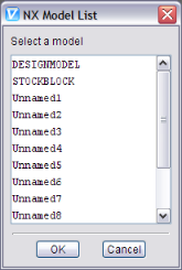
Since a NX part file can contain multiple models, a pop-up window displays with a list of models contained in the NX part file. If a model was named in NX, it is listed by name in the window. If the model was not named in NX, it is displayed in the list as "Unnamed" followed by a number as shown in the picture below.
Use of these files in Vericut requires an NX Model Interface license, and the installation of the CAD Model Interface files (aka the \"Spatial Technologies\" libraries).
See the Vericut website for additional information on the NX Model Interface.
Also see Installing the Model Interface Modules in the Installing Vericut Products or Installing Vericut Composite Applications section of the Vericut Help Library.
Operations File
Typical file extension: .ops and .vctmp
Introduction
An Operations File, or or ops-file, can be used to assemble a project with multiple setups from several VERICUT project files, which typically have the extension ".VcProject". This assembly process can only be triggered from the command line that invokes VERICUT. The typical command line syntax is;
| For Windows ... | "ops=c:\My\Path\MyOperationsFile.ops" ... |
|---|---|
Any extension can be used in the file name, but by convention ".ops" is used for most files and ".vctmp" denotes a temporary file.
An Operations File is a human-readable text file. Each line of the file is independent and references a VERICUT project file. A line requests that information from its project file should be transferred to the project being assembled. A line can request that the entire project and all its setups be transferred, or that information from one setup be transferred, or that all the setup-independent information, which we will refer to as project information, be transferred. It is suggested that the first line of the file should always request at least the project information from a ".VcProject" file that was saved by VERICUT, so that the new project will have a good foundation.
Syntax
In the following explanation the Windows path delimiter, "/", is used. Names should be enclosed in double quotation characters ("). Fields are separated by one or more spaces.
Project data
The first keyword of each ops-file line record must be ALL, PROJECT, or SETUP. As explained in the introduction, the first record should define a starting project, so it is expected to start with ALL or PROJECT.
To request that the entire project, with all its setups, be transferred to the new project being assembled, the syntax of the required line is:
ALL FILE="My\Path\MyProjectTemplate.VcProject"
Note that choosing this option means the subsequent setups transferred to the new project will be appended to the setups of the project template (“MyProjectTemplate.VcProject” in the example above), as opposed to overwriting them. In other words the new project’s setup list will start with the exact copies of all the project template setups.
To request that the setup-independent project information from a file be transferred to the new project, the syntax of the required line is:
PROJECT FILE="My\Path\MyProjectTemplate.VcProject"
Setup-independent information in a project file pertains to the following VERICUT menu items:
-
Model Export
-
Colors
-
View Capture
-
AutoSave
-
Status
-
Graphs
-
Cycle Definitions
-
AUTO-DIFF
What happens when an ops-file starts with these two lines?
PROJECT FILE="Template1.vcproject"
PROJECT FILE="Template2.vcproject"
Answer: The first project Template1 will be completely overwritten with the second, Template2. So the first line referring to Template1.vcproject becomes irrelevant and should be deleted.
Setup Data
To request that setup information from a file be transferred to the new project, the syntax of the required line is;
SETUP NAME="Setup A" INDEX=1 SETUP=1 MERGE MERGE_TOOLS FILE="\Path\Tmp.VcProject"
The NAME field specifies the name that the setup will have in the new project.
The INDEX field selects which of the setups in the referenced file will be transferred. An index value of "1" selects the first setup in the file, "2" would use the second setup, etcetera. The INDEX field is optional and defaults to 1 if not present.
The SETUP=n field specifies the index of the setup in the merged file that this line refers to. It is optional and is only required if the MERGE_TOOLS field is present.
The MERGE field specifies that all setup data other than the tool library associated with the setup being imported should be merged with the current setup data rather than overwriting it. For example, G-Code Tables will be merged, not replaced, if the MERGE option is included. Another example would be NC Programs which will be merged, not replaced. This field is optional.
The MERGE_TOOLS field specifies that the tool library associated with the setup being imported should be merged with the current tool library rather than overwriting it. This field is optional.
The FILE field references the Vericut project file that contains the required setup.
More than one SETUP line in the Operations File can have the same NAME field. The first such line would cause a new setup to be appended to the project being assembled, and subsequent lines could adjust the parameters of that same setup. Setup specific information in a project file pertains to the following Vericut menu items:
-
Views
-
Sections
-
Components and Models
-
NC Programs and Filters
-
Tools and Tool Changes
-
APT and G-Code Settings
-
Coordinate Systems
-
Control
-
Machine
-
Inspection
-
Die Sinking
-
Optimization
Project Naming
The name and location of the assembled project file will be derived from the name and location of the Operations File. The extension ".VcProject" will replace any extension that the Operations File's name has, and the assembled project will be placed in the same folder. This assumes that the user saves the project before explicitly renaming it and before exiting Vericut. To remind the user that he needs to save the project before exiting, you can include another keyword on the command line. Thus you may have;
... "ops=C:\My\Path\MyOperationsFile.VcTmp" ...
Post-Processor File
Typical file extension: .VcPost
A Post-Processor file is an ASCII text file, created using the Vericut Post Processor, containing all the information required to read machine independent NC Program data and convert it to G-Code files for a specific machine/control combination.
Preferences File
Typical file extension: .prefs
Also known as a "Prefs file", this ASCII text file is automatically saved when you exit Vericut and stores such user preferences as:
-
Vericut user interface Look & Feel
-
size and locations of Vericut windows
- state of menu toggles in any window that has them, for example: Project tab >Axes, etc.
- filters for Vericut file selection windows
- recent User/Project files opened in Vericut
The Preferences file is unique for each Vericut version and each user, based on your login. The file is named "cgtech_version#_user.prefs" where version# is the current Vericut version number. For example, a Prefs file for Vericut 9.7 has the name "cgtech_82_user.prefs". The Prefs file is automatically stored in your home folder and is updated each time you exit Vericut.
When users share a computer (or an account), Vericut recommends that each user set a unique CGTECH_USERNAME environment variable to prevent overwriting the Preferences file. See Environment Variables section of Vericut Help for more information.
To reset Preferences file settings:
Windows Start > All Programs > Vericut Vericut x.x.x > Utilities > Reset Preferences
where x.x.x is the Vericut release number, for example 9.7
Click here to see a sample Preferences file "cgtech_user.prefs".
Project File
Typical file extension: .vcproject
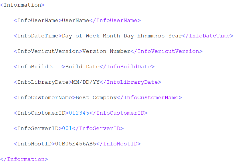
A Vericut Project file is an XML (Extensible Markup Language) text file containing Vericut session settings, also known as "user configuration values" or "user values", including: measurement units, colors, choices, data field values, folder paths and file names, etc. Project files are used in Vericut and are relatively small in size, yet can control the entire cutting process and minimize the effort required to configure the system for processing NC program files.
While Project files are used in Vericut, Vericut Composite Simulation, and Vericut Drill and Fastener Simulation, project files created in one system are not compatible with another.
A Project file created in Vericut cannot be used in Vericut Composite Simulation or Vericut Drill and Fastener Simulation.
One of the following warning messages is output if you load a Project file that is not compatible with the current system.
The warning, "You are opening a VCS project file in Vericut.", is output when a Vericut Composite Simulation project file is loaded in Vericut.
The warning, "You are opening an AutoFastener project file in Vericut.", is output when a Vericut Drill and Fastener Simulation project file is loaded in Vericut.
Project files are saved via the ![]() (Save Project) icon in the Quick Access Toolbar or the
(Save Project) icon in the Quick Access Toolbar or the  feature in the Project File group of the File tab. Project files are loaded via the
 ![]() (Open Project) icon in the Quick Access Toolbar or the
(Open Project) icon in the Quick Access Toolbar or the  feature in the Project File group of the File tab. Project files can also be specified on the command line when Vericut is executed, such as during batch processing to simulate NC programs without user interaction.
The following user and version related information is also saved in the project file:
Report Template File
Typical file extension: .VcTemplate
A Report Template file is an XML (Extensible Markup Language) text file containing all of the formatting information required to generate Vericut reports.
Review File
Typical file extension: .vcreview
The Review file is a binary file that contains all of the information required to simulate a Vericut Project file. It contains the model information required to display machine, cut stock, tools etc. It also contains the NC program(s) used to cut the part, tool path data, original view settings and a copy of the Log file.
Simulated Locations File
Typical file extension: .xml
A Simulated Locations File is an XML (Extensible Markup Language) text file. Similar to a Design Locations File, it contains location data, hole characteristics, fastener characteristics, stack counts and stack thickness, etc. The difference is that the Simulated Locations File contains data collected by Vericut Drill and Fastener Simulation during the simulation of the NC program(s).
To save a Simulated Locations file, right-click on Simulated Locations in the Project Tree panel and then Select Output from the menu that displays to display the "Save a fastener locations file" file selection window enabling you to specify the /path/filename for the Simulated Locations File that you are saving.
Status File
Typical file extension: .txt
An ASCII text file that contains whatever data is sent to the Status window during the simulation (ref. Status Window in the Info tab section of Vericut Help). A Status file is created when the CGTECH_STATUS environment variable is set to a file name before Vericut is executed. The file is overwritten when the Vericut model is reset.
For each NC program record processed, the following status data is written:
REC — Indicates a NC program record processed.
REC fields — NC program Record Line Number, NC program Record
DATA — Specifies most of the status values separated by commas. Fields not displayed in the Status window are represented by commas.
DATA fields — Mch Axis Loc- X, Y, Z, A, B, C, U, V, W, Tool Tip Loc- X, Y, Z, I, J, K, Errors, Warnings, Time, Time%, Dist, - Dist%, Coolant, Feedrate, OP Feedrate, Spindle, OP Spindle
TOOLCHANGEREC — The record which caused the last tool change (present only if the Status window is configured to show this field).
TOOLDESC — The current tool description (present only if the Status window is configured to show this field).
TOOLGEOMETRY — The current tool geometry (present only if the Status window is configured to show this field).
APT example:
REC,12,GOTO/3,2,1
DATA,,,,,,,,,,,,,,,,3,,,,0,0,0.5355,,,,ON ,10 IPM,,500,CLW ,
TOOLCHANGEREC,CUTTER/1.125,.25,0,0,0,0,2.1
Click here to see a sample APT Status File
G-Code example:
REC,20,N0130G0X-.2Y-.3Z2.S1200M3
DATA,,,,,,,,,,,,,,,,19,,,4,0,0,1.6979,,,,OFF,2 IPM,,1200,
TOOLCHANGEREC,N0120T4M6
STEP Model File
Typical file extension: .stp or .step
A STEP model file is a 3D model file formatted in STEP (Standard for the Exchange of Product Data), an ISO standard exchange format; used for representing three-dimensional model data in a format that can be recognized by multiple programs. A STEP model file is an ASCII text file.
See the Vericut website for additional information on the STEP Model Interface.
Also see Installing the Model Interface Modules in the Installing Vericut Products or Installing Vericut Composite Products section of the Vericut Help Library.
Stereolithography (STL) Model File
Typical file extension: .stl
A Stereolithography model file, also known as an "STL" or "SLA" file, is an ASCII text or binary file which describes virtually any surfaced or solid model shape. The STL data representing the model shape is composed of three-sided facets with associated surface normals. STL files typically originate from a CAD system and represent an enclosed model used by an SLA machine, such as developed by 3D Systems.
Load Stereolithography model files into Vericut via the Configure Model menu, Model tab (ref. Configure Model menu, Model tab in the Project Tree section of Vericut Help). For an STL file to be used in Vericut as a solid model, the STL data must represent a fully enclosed (watertight) model and have normals that point consistently outward. (STL files used as surface models do not have to be watertight.) If normals are inconsistent, gaps exist between facets, or facets overlap, solid model display results are unpredictable. When cutting is started or the model is analyzed, these symptoms indicate problems exist in the model file data:
-
model is not displayed at all
-
model is displayed with holes, gaps, or seams
- portions of the model are missing
Tip: If any of the above symptoms are experienced, use the PolyFix Converter and/or the Stock Consistency Check feature (ref. Settings window: Properties tab in the Project tab section of Vericut Help.) to repair the model before cutting. Similar advice applies for models added to Design components for use with AUTO-DIFF, except the Design Consistency Check feature is used (ref. AUTO-DIFF: Options tab in the Analysis tab section of Vericut Help).
Click here to see a sample STL Model File
Tool Library File
Typical file extension: .tls
An ASCII text file that contains descriptions of cutting tools, shanks and holders, as well as other tool data used by Vericut. Specific tool data is stored and retrieved via a tool "ID".
This file is created and maintained via the Tool Manager > Project tab > Tools features. You can save the new file via File tab > Save File > Save As in Tool Manager.
The following user and version related information is also saved in the project file:
The Tool Library file to be used by Vericut is specified via the Configure Tooling menu (ref. Configure Tooling menu in the Project Tree section of Vericut Help).
📝 NOTE: If errors occur when attempting to load the file, contact Vericut technical support via our website, just click on the support link for assistance.
Click here to see a sample Tool Library File
Tool Manager Report File
Typical file extensions: .htm (HTML version), .txt (test version)
An HTML or text file that contains information about tools in a Vericut Tool Library file, such as: the Tool Library name, listing of tools, tool images (HTML version only), and optimization properties, if defined. Tool Manager Report files are created and viewed from the Tool Manager window via clicking Report pulldown menu features.
Click here to see a sample Tool Manager Report File
Vericut Linear Sweep File
Typical file extension: .swp
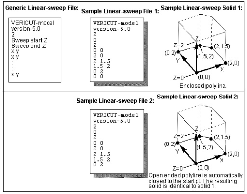
A Vericut Linear-sweep file, or "Linear-sweep file" for short, is an ASCII text file that describes an extruded shape. A 2-D profile is defined in the XY plane, then swept (extruded) along the model's Z axis.
Linear-sweep files are loaded into Vericut via the Configure Model menu, Model tab (ref. Configure Model menu, Model tab in the Project Tree section of Vericut Help), and contain the following data:
File type record — Specifies the type of Vericut file, for example "Vericut-model".
Version number record — Software version in which the file is to be used, for example "version-3.0".
Model file identifier record — Model file type: "2" identifies a Linear-sweep file.
Sweep start value — Z value of the linear sweep start.
Sweep end value — Z value of the linear sweep end.
Polyline data — The remaining records in the file are the XY point pairs which define the polyline to extrude. Each X and Y value must be on a separate line with a space between values. There is no limit on the number of point pairs allowed, but there must be at least 3 pairs. The polyline can be completely enclosed or open ended, but cannot cross over itself. Open ended polylines are automatically closed to the start point.
Vericut Polygon File
Typical file extensions: design- .dsn, fixture- .fix, stock- .stk, any- .ply
A Vericut Polygon file, or "Polygon file" for short, is an ASCII text file that describes virtually any shape open surface or enclosed shape. The polygon (faceted) data is composed of three or four sided polygons with associated surface normals that represent the true geometric model shape.
Load Polygon model files into Vericut via the Configure Model menu, Model tab (ref. Configure Model menu, Model tab in the Project Tree section of Vericut Help). For a Polygon file to be used in Vericut as a solid model, the polygon data must represent a fully enclosed (watertight) model and have normals that point consistently outward. (Polygon model files used as surface models do not have to be watertight.) If normals are inconsistent, gaps exist between facets, or facets overlap, solid model display results are unpredictable. When cutting is started or the model is analyzed, these symptoms indicate problems exist in the model file data:
-
model is not displayed at all
-
model is displayed with holes, gaps, or seams
- portions of the model are missing
Tip: If any of the above symptoms are experienced, use the PolyFix Converter and/or the Stock Consistency Check feature (ref. Project tab > Settings > Properties tab) to repair the model before cutting. Similar advice applies for models added to Design components for use with AUTO-DIFF, except the Design Consistency Check feature is used (ref. Analysis tab > AUTO-DIFF, Options tab).
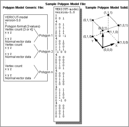
Polygon file format:
File type record — Specifies the type of Vericut file, for example "Vericut-model".
Version number record — Software version in which the file is to be used, for example "version-3.0".
Model file identifier record — Model file type: "1" specifies a Polygon file.
Sweep start value — Z value of the linear sweep start.
Sweep end value — Z value of the linear sweep end.
Polygon format record — Describes the surface normal data and vertex data formats. This record contains three integer numbers separated by blanks: n1 n2 n3 (e.g. "0 0 1") where:
n1 (normal vector type) — Specifies the type of surface normal vector information present in the polygon file.
-
0 - each polygon has one normal vector
-
1 - each vertex has a normal vector
n2 (normal vector direction) — Specifies the surface normal vector direction relative to the model surface.
-
0 - normal vectors point inward
-
1 - normal vectors point outward
-
2 - normal vector directions are inconsistent (should ONLY be used after both the "0" and "1" values have been attempted with unfavorable results; requires significantly more processing time and computer resources)
n3 (Polygon format type) — Specifies the polygon data format.
-
0 - binary data format (recommended- requires less storage space and is processed faster, however, binary formatted files are computer-specific)
-
1 - ASCII data format
Polygon data — The remaining records in the file are the polygon data records which define the model shape. Each model facet (or polygon) is represented by a series of records describing its number and location of vertices, as well as surface normal vector direction(s). There is no limit on the amount of data allowed.
Two polygon data formats are supported. The polygon data type must be consistent for the entire file.
Format 1 - 1 normal per polygon:
vertex count (3 or 4)
X Y Z (vertex 1)
X Y Z (vertex 2)
X Y Z (vertex 3)
I J K (normal)
Format 2 - 1 normal per vertex:
vertex count (3 or 4)
X Y Z (vertex 1)
X Y Z (vertex 2)
X Y Z (vertex 3)
I J K (normal 1)
I J K (normal 2)
I J K (normal 3)
Sample Polygon file:
Vericut Solid-of-Revolution File
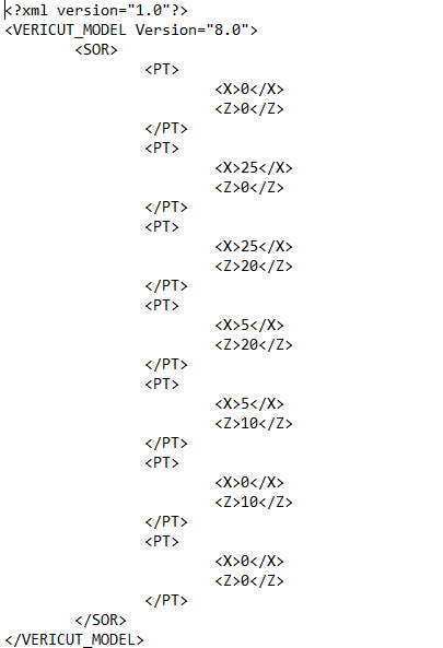
Typical file extension: .sor
A Vericut Solid-of-revolution file, or "Solid-of-revolution file" for short, is an ASCII text file that describes a revolved shape. A 2-D profile is defined in the ZX plane, then revolved around the model's Z axis.
Solid-of-revolution files are loaded into Vericut via the Configure Model menu, Model tab (ref. Configure Model menu, Model tab in the Project Tree section of Vericut Help), and contain the following data:
File type record — Specifies the type of Vericut file, for example "Vericut-model".
Version number record — Software version in which the file is to be used, for example "version-5.0".
Model file identifier record — Model file type: "0" identifies a Solid-of-revolution file.
Tolerance of revolution — Chordal tolerance (intol) of the revolved surface, controls the S.O.R.'s degree of roundness for the model database.
Polyline data — The remaining records in the file are the XZ point pairs which define the polyline to revolve. Each X and Z value must be on a separate line with a space between values. There is no limit on the number of point pairs allowed, but there must be at least 3 pairs. X values must be greater than or equal to zero. The polyline can be completely enclosed or open ended, but cannot cross over itself. Open ended polylines are automatically closed to the start point.