Macros Documentation
A Vericut macro is a script or command within Vericut CNC simulation software that automates tasks, customizes machine behaviors, and integrates with CAM systems to enhance simulation efficiency and setup.
A2AxisIncreMotion
-
Function — MOTION
-
Status — ACTIVE
-
Input —
- Text: First character is used to determine the sign of the value if the value is zero
- Value: Incremental amount to move the component
The macro calls A2AxisMotion and processes the value as an incremental motion. This will be processed at the end of the block, or when ProcessMotion is called.
A2AxisMachineMotion
-
Function — MOTION
-
Status — ACTIVE
-
Input —
- Text: Not used
- Value: Position to move component in the machine coordinate system
Specifies the absolute position, within the machine coordinate system, to move the A2 axis component on the current subsystem. This will be processed at the end of the block, or when ProcessMotion is called. Travel Limit warnings for this component will be turned off for this motion.
With robot, if SetRobotLogicVersion is set with value lower than 3, it will also implicitly set motion to Forward Kinematics (Direct Drive of axis) for compatibility with older configurations:
-
CartesianModeOnOff Value = 0
-
SetRobotMotionType Value = 0
A2AxisMachineRefMotion
-
Function — MOTION
-
Status — ACTIVE
-
Input —
- Text: Not used
- Value: Position to move component relative to the reference location.
Specifies the position, relative to the Machine Reference Location, to move the A2 axis component on the current subsystem. This will be processed at the end of the block, or when ProcessMotion is called. More specifically, this macro adds the input value and the corresponding value from the Machine Reference Location table, and then calls A2AxisMachineMotion.
See also — A2AxisMachineMotion (ref. Machine Reference Location table in the Tables for Processing G-Codes section, in the CGTech Help Library).
A2AxisMotion
-
Function — MOTION
-
Status — ACTIVE
-
Input —
- Text: First character is used to determine the sign of the value if the value is zero
- Value: Position to move component within the local coordinate system.
Sets the local axis position for the A2 axis component on the current subsystem. This will be processed at the end of the block, or when ProcessMotion is called.
The above is the simple description of this macro based on how this macro is most commonly used. There is, however, a series of special logic that could apply under special circumstances.
- If the IncrementalValue function was used to set the value, the input value will be added to the current A2 Axis value.
- If Siemens ACP, ACN, or DC function was used, the value is adjusted accordingly.
- If Siemens, we update the A2 mirror flag based on the setting of the $P_ACTFRAME variable and the SiemensMirrorUpdate flag.
- If mirroring A2, we adjust the A2 value. See also MirrorA2 and MirrorA2Value.
-
Based on the Rotary Type and the Rotary Direction, we update the value accordingly.
-
With robot, if SetRobotLogicVersion is set with value lower than 3, it will also implicitly set motion to Forward Kinematics (Direct Drive of axis) for compatibility with older configurations:
-
CartesianModeOnOff Value = 0
-
SetRobotMotionType Value = 0
-
A3AxisIncreMotion
-
Function — MOTION
-
Status — ACTIVE
-
Input —
- Text: First character is used to determine the sign of the value if the value is zero
- Value: Incremental amount to move the component.
The macro calls A3AxisMotion and processes the value as an incremental motion. This will be processed at the end of the block, or when ProcessMotion is called.
A3AxisMachineMotion
-
Function — MOTION
-
Status — ACTIVE
-
Input —
- Text: Not Used
- Value: Position to move component in the machine coordinate system
Specifies the absolute position, within the machine coordinate system, to move the A3 axis component on the current subsystem. This will be processed at the end of the block, or when ProcessMotion is called. Travel Limit warnings for this component will be turned off for this motion.
With robot, if SetRobotLogicVersion is set with value lower than 3, it will also implicitly set motion to Forward Kinematics (Direct Drive of axis) for compatibility with older configurations:
-
CartesianModeOnOff Value = 0
-
SetRobotMotionType Value = 0
A3AxisMachineRefMotion
-
Function — MOTION
-
Status — ACTIVE
-
Input —
- Text: Not used
- Value: Position to move component relative to the reference location.
Specifies the position, relative to the Machine Reference Location, to move the A3 axis component on the current subsystem. This will be processed at the end of the block, or when ProcessMotion is called. More specifically, this macro adds the input value and the corresponding value from the Machine Reference Location table, and then calls A3AxisMachineMotion.
See also — A3AxisMachineMotion (ref. Machine Reference Location table in the Tables for Processing G-Codes section, in the CGTech Help Library).
A3AxisMotion
-
Function — MOTION
-
Status — ACTIVE
-
Input —
- Text: First character is used to determine the sign of the value if the value is zero
- Value: Position to move component within the local coordinate system.
Sets the local axis position for the A3 axis component on the current subsystem. This will be processed at the end of the block, or when ProcessMotion is called. The above is the simple description of this macro based on how this macro is most commonly used. There is, however, a series of special logic that could apply under special circumstances.
- If the IncrementalValue function was used to set the value, the input value will be added to the current A3 Axis value.
- If Siemens ACP, ACN, or DC function was used, the value is adjusted accordingly.
-
Based on the Rotary Type and the Rotary Direction, we update the value accordingly.
-
With robot, if SetRobotLogicVersion is set with value lower than 3, it will also implicitly set motion to Forward Kinematics (Direct Drive of axis) for compatibility with older configurations:
-
CartesianModeOnOff Value = 0
-
SetRobotMotionType Value = 0
-
AAxisIncreMotion
-
Function — MOTION
-
Status — ACTIVE
-
Input —
- Text: First character is used to determine the sign of the value if the value is zero
- Value: The incremental amount to be moved.
Similar to AAxisMotion except it ignores the Absolute / Incremental mode setting, and increments by the value specified.
On robot cell axis, it will also implicitly set motion to Forward Kinematics (Direct Drive of axis):
-
CartesianModeOnOff Value = 0
-
SetRobotMotionType Value = 0
AAxisMachineMotion
-
Function — MOTION
-
Status — ACTIVE
-
Input —
- Text: Not used
- Value: Position to move component in the machine coordinate system
Specifies the absolute position, within the machine coordinate system, to move the A axis component on the current subsystem. This will be processed at the end of the block, or when ProcessMotion is called. Travel Limit warnings for this component will be turned off for this motion.
With robot, if SetRobotLogicVersion is set with value lower than 3, it will also implicitly set motion to Forward Kinematics (Direct Drive of axis) for compatibility with older configurations:
-
CartesianModeOnOff Value = 0
-
SetRobotMotionType Value = 0
AAxisMachineRefMotion
-
Function — MOTION
-
Status — ACTIVE
-
Input —
- Text: Not used
- Value: Position to move component relative to the reference location.
Specifies the position, relative to the Machine Reference Location, to move the A axis component on the current subsystem. This will be processed at the end of the block, or when ProcessMotion is called. More specifically, this macro adds the input value and the corresponding value from the Machine Reference Location table, and then calls AAxisMachineMotion.
See also — AAxisMachineMotion (ref. Machine Reference Location table in the Tables for Processing G-Codes section, in the CGTech Help Library).
AAxisMotion
-
Function — MOTION
-
Status — ACTIVE
-
Input —
- Text: First character is used to determine the sign of the value if the value is zero
- Value: Position to move component within the local coordinate system.
Sets the local axis position for the A axis component on the current subsystem. This will be processed at the end of the block, or when ProcessMotion is called. The above is the simple description of this macro based on how this macro is most commonly used. There is, however, a series of special logic that could apply under special circumstances.
- If the IncrementalValue function was used to set the value, the input value will be added to the current A Axis value.
- If Siemens ACP, ACN, or DC function was used, the value is adjusted accordingly.
- If Siemens, we update the A mirror flag based on the setting of the $P_ACTFRAME variable and the SiemensMirrorUpdate flag.
- If mirroring A, we adjust the A value. See also MirrorA and MirrorAValue.
-
Based on the Rotary Type and the Rotary Direction, we update the value accordingly.
-
With robot, if SetRobotLogicVersion is set with value lower than 3, it will also implicitly set motion to Forward Kinematics (Direct Drive of axis) for compatibility with older configurations:
-
CartesianModeOnOff Value = 0
-
SetRobotMotionType Value = 0
-
AAxisMotionVirtualAdjust
-
Function — MOTION
-
Status — Active
-
Input —
- Text: Not Used
- Value: Virtual “A” angle.
-
Comment — Added V7.1.5
-
Input —
- Text: Not Used
- Value: Virtual “A” angle.
Note — This is an Electro Inpact specific macro. It converts the input virtual angle into a real A Axis angle taking into account the Virtual Center defined with the EIVirtualSpinPoint macro. On robot cell axis, it will also implicitly set motion to Forward Kinematics (Direct Drive of axis):
-
CartesianModeOnOff Value = 0
-
SetRobotMotionType Value = 0
AbBlockInit
-
Function — EVENTS
-
Status — ACTIVE
-
Input —
- Text: Not Used
- Value: Not Used
This macro is used to initialize Allen-Bradley specific variables. This macro should be called along with the standard BlockInit macro at the "Start of Block Processing" event.
ABCPos
-
Function — MOTION
-
Status — ACTIVE
-
Input —
- Text: Defines the input angle, “A”, “B”, or “C”, defaults to the current Word
- Value: Angle value
-
Comment — Added V7.1
-
Input —
- Text: Defines the input angle, “A”, “B”, or “C”, defaults to the current Word
- Value: Angle value
See Also — SetRobotCsys Note — This is a robot specific macro. Sets the A, B, or C angle values used to define the tool axis vector using RPY angles. The A, B and C values (for example, A0 B20 C0) are used to calculate the tool vector for the next tool position. This method can be used instead of direct IVector, JVector and KVector macros defining components of the tool vector and is specific for the robots. The tool axis vector can be transformed to user specified coordinate system. By default, this macro detects the A, B or C based on the Word. Using an Override Text value of "A,B,C" enables you to indicate that format A:0 B:20 C:0 should be accepted. Any other value entered in the Override Text field is ignored.
AbsoluteShift
-
Function — SHIFT OFFSETS
-
Status — ACTIVE
-
Input —
- Text: Not Used
- Value: Not Used
This macro is used to shift the work coordinate system by the specified axis values. The values will be interpreted as absolute. Any axis value which is not specified is assumed to be zero. (Shift Offset 0, ABSOLUTE/NON-MODAL).
AbsoluteShift2
-
Function — SHIFT OFFSETS
-
Status — ACTIVE
-
Input —
- Text: Not Used
- Value: Not Used
This macro is used to shift the work coordinate system by the specified axis values. The values will be interpreted as absolute. If "MODAL" is not specfied, any axis value which is not specified is assumed to be zero. If "MODAL" is specified, only the axis values specified will be updated.
The index value specifies which Shift Offset is being update.
NOTE: The index values for this macro are 1-5 (not 0-4). This is different than most other shift macros, but is consistent with the Machine Offsets window.
NOTE: The axis values are specified with the WorkCoord*Value macros.
AbsoluteShiftLocal
-
Function — Rotation Plane
-
Status — ACTIVE
-
Input —
- Text: Optional: “MODAL”
- Value: Specifies which shift index to use (0, 1, 2)
-
Comment — s: added V8.0
-
Input —
- Text: Optional: “MODAL”
- Value: Specifies which shift index to use (0, 1, 2, 3, 4)
This macro implements an absolute shift. This shift is specified with the WorkCord… macros. This input is in local coordinates, and is for the current rotation.
Note — This macro is based on the currentDynamic Work Offsets settings.
If “MODAL” is set, it will only update the fields that were specified. This is very complicated, for> example:
-
The C table is rotated to 90 degrees. Assume that Dynamic Work Offsets are turned on.
-
The AbsoluteShiftLocal macro is called with a Y5 Z10 shift. We will convert this to be a X5 Z10 offset that is rotated 90 degrees. This macro is then called again, this time with a Y7. The current X5 Z10 offset will be converted back to Y5 Z10, and then only the Y will be updated. Then end result is a Y7 Z10 offset which is then converted to a X7 Z10 offset that is rotated 90.
AbsoluteShiftModal
-
Function — MOTION
-
Status — ACTIVE
-
Input —
- Text: Not Used
- Value: Not Used
This macro is used to shift the work coordinate system by the specified axis values. The values will be interpreted as absolute. Only values specified on the block will be adjusted. (Shift Offset 0, ABSOLUTE/MODAL)
AbsoluteShiftNum
-
Function — MOTION
-
Status — ACTIVE
-
Input —
- Text: Not Used
- Value: Not Used
This macro is used to shift the work coordinate system by the specified axis values. The values will be interpreted as incremental or absolute depending on the current state, incremental (ModeIncremental) or absolute (ModeAbsolute), of the control. Only values specified on the block will be adjusted. (Shift Offset 1, ABSOLUTE/MODAL or INCREMENTAL).
AbsoluteShiftRotationDynamic
-
Function — SHIFT OFFSETS
-
Status — ACTIVE
-
Input —
- Text: Optional “MODAL” value
- Value: Not Used
-
Comment — Added V6.2
-
Input —
- Text: Optional “MODAL” value
- Value: Not Used
This macro was modeled after IncrementalShiftRotationDynamic. The basic concept is that the offset is currently being defined within the current "working plane". This "working plane" is a combination of the rotation plane and the orientation of the stock. The offset specified (with the WorkCoord...Value macros) will be multiplied by the current rotation plane, and then if dynamic work offsets are turned on, it will be un-rotated by the current rotation of the stock. This shift offset would be applied as: (Shift Offset 0, ABSOLUTE) If the Text value is "Modal", the original non-rotated offset will be considered Modal.This means that if an X offset is specified on one line, and a Y offset is specified on another line, this will be treated the same as if X and Y were on the same line.
AbsoluteShiftRotationDynamicIndex
-
Function — SHIFT OFFSETS
-
Status — ACTIVE
-
Input —
- Text: Optional “MODAL” value
- Value: The shift index to be used (0, 1, or 2)
-
Comment — Added V7.0.2
-
Input —
- Text: Optional “MODAL” value
- Value: The shift index to be used (0, 1, or 2)
This macro is designed for the Siemens 840D control to process TR (trans) values in $P_PFRAME. This macro is modeled after IncrementalShiftRotationDynamicIndex. The basic concept is that the offset is currently being defined within the current "working plane". This "working plane" is a combination of the rotation plane and the orientation of the stock. The offset specified (with the WorkCoord...Value macros) will be multiplied by the current rotation plane, and then if dynamic work offsets are turned on, it will be unrotated by the current rotation of the stock. This shift offset would be applied as: (Shift Offset 0, ABSOLUTE). The Override Value is used to specify the shift index to be used and can be an integer value from 0 to 2. If the Text value is "Modal", the original non-rotated offset will be considered Modal.This means that if an X offset is specified on one line, and a Y offset is specified on another line, this will be treated the same as if X and Y were on the same line.
AbSyncChannelCommand
-
Function — SYNC
-
Status — ACTIVE
-
Input —
- Text: Not Used
- Value: Channel number:
-
Comment — Added V7.0.1
-
Input —
- Text: Not Used
- Value: Channel number:
- 1 = command for channel 1
- 2 = command for channel 2
- 3 = command for both channels
This is an Allen-Bradley specific macro. The Allen Bradley documentation states that:
-
"Start Of Block synchronization occurs when a block of information contains..."
-
"Any command, or combination of commands, that affect both axis pairs".
-
This macro is used to track any of these commands that are present on the current block. If a block contains one of these commands for both channels, then a sync will be done. The value passed to this macro represents the channel that this command is associated with.
ABType2CLS
-
Function — TYPE2
-
Status — ACTIVE
-
Input —
- Text: Not Used
- Value: Not Used
An Allen Bradley, Type II, subroutine call with no arguments. Same as Type2CLS, except it strips all characters starting with the "/" character.
Example — (CLS,027sta/hd) would call subroutine file "027sta".
AccelDecelLogic
-
Function — ACCEL/DECEL
-
Status — ACTIVE
-
Input —
- Text: Not used
- Value: 0 = original (default), 1 = old, 2 = new look ahead
-
Comment — Added in V8.2
-
Input —
- Text: Not used
- Value: 0 = original (default), 1 = old, 2 = new look ahead
This macro determines which Accel/Decel logic is used.
Quick summary —
-
Option 0: It is recommended to never use this option, except for robots.
-
Option 1: An improved version of option 0.
-
Option 2: An improved version of option 1. Uses look ahead for greater accuracy. Also, this is the only version which produces accurate times while optimizing (without having to rerun Vericut).
-
All options uses the 4 Accel/Decel parameters (for each axis) to calculate the effect of accel/decel on the time for each motion.
-
Acceleration: How fast can it accelerate up to the specified feedrate
-
Decelerate: How fast can it decelerate. Note: Each axis must decelerate down to the corner velocity before starting the next block
-
Max Feed Rate: Maximum velocity for the axis
-
Max Velocity for Direction Change: The exact meaning of this option is different depending on the AccelDecelLogic. In general, the concept is, what should the velocity be at a corner. NOTE: if this value is set to zero, this will simulate “Exact Stop”. Here the machine comes to an exact stop on each motion.
Note —
-
Robots: For robots, this option when combined with SetRobotLogicVersion >= 2, calls a new cycle time calculation, dedicated to robot, and makes possible to export kinematic data (see Ribbon > Info > Report group > Export robot axis kinematic data).
-
Optimizing: Traditionally when optimizing, the accel/decel logic would modify the blocks in order to make sure the feedrates are achievable. Starting with Option 2, the optimizing accel/decel logic is the same as non-optimizing. Here the focus is not on changing the blocks, but just adjusting the time.
-
Option 2: We believe this is our more accurate algorithm. It is a look ahead version of Option 1. This allows us to adjust the Max Velocity for Direction Change based on the direction of the next motion relative to the current direction. When using this option, the old optimizing logic will no longer be used. The concept is: output the feedrate based on optimization and let the machine determine how best to achieve this. Accel/Decel is strictly for time calculations. NOTE: The time we calculate when optimizing should be the same time you get if you run the optimized program.
AccelTakeoffFactor
-
Function — ACCEL / DECEL
-
Status — ACTIVE
-
Input —
- Text: Not Used
- Value: Factor to be used when outputting accel blocks. 0 = Don’t output accel blocks.
This macro is used to control the length of the accel block output during optimization for motions in a corner. When called with a value greater than "0", Optimization outputs an accel block when suitable. A value of "0" (default) causes the accel block to not be output. The value passed represents a % override to apply to the calculated length for normal accel block output. For example, a value of "1.0" specifies that 100% of the calculated accel block length should be used, while "0.5" uses 50% of the calculated length.
Accudyne2CourseDist
-
Function — TAPE LAYING
-
Status — ACTIVE
-
Input —
- Text: Not used
- Value: Course Distances for an Accudyne Tape machine
-
Comment — Added in V7.1.4
-
Input —
- Text: Not used
- Value: Course Distances for an Accudyne Tape machine
This macro sets the distance along the current course at the end of this block.
Note — This value is used determine when tape starts and stops
AccudyneClearAddOnCut
-
Function — TAPE LAYING
-
Status — ACTIVE
-
Input —
- Text: Not used
- Value: Not used
-
Comment — Added in V8.2.2
-
Input —
- Text: Not used
- Value: Not used
This macro is specific to the Accudyne AFP control. This macro resets (to zero) the ADD_ON and CUT variables. See also: AccudyneSetAddOnCut.
AccudyneCourse
-
Function — TAPE LAYING
-
Status — ACTIVE
-
Input —
- Text: Not Used
- Value: New course number for an Accudyne Tape machine.
-
Comment — Added V7.1.4
-
Input —
- Text: Not Used
- Value: New course number for an Accudyne Tape machine.
Note — Since the ADDS and CUTS variables (which are used to determine when tows are turned "on" and "off"), are based on the distance from the start of the course, and the distance value is based on the total distance within the file, we must track the changing of the course to mark the starting distance for the current course.
AccudyneCourseDist
-
Function — TAPE LAYING
-
Status — ACTIVE
-
Input —
- Text: Not Used
- Value: Course Distance for an Accudyne Tape machine.
-
Comment — Added V7.1.4
-
Input —
- Text: Not Used
- Value: Course Distance for an Accudyne Tape machine.
This macro sets the current distance value. This distance is the total distance of all courses within this file. If the distance is zero, the ADDS and CUTS variables are read. This determines when each tow is turned on and off. If MULTI is specified on the text argument, then we will support multiple on/off per course.
AccudyneSetAddOnCut
-
Function — TAPE LAYING
-
Status — ACTIVE
-
Input —
- Text: Not used
- Value: Not used
-
Comment — Added in V8.2
-
Input —
- Text: Not used
- Value: Not used
This macro is specific to the Accudyne AFP control. It uses the ADD_ON and CUT variables to determine where tape is to be laid. Both ADD_ON and CUT is a double array variable. A tow can be turned off and back on again. The first index which occurrence of turning on/off the tow. The second index corresponds to the tow. The value indicates when this tow is to be turned on/off.
For ADD_ON, the actual turn on point is:
- Specified value + nip distance – prefeed distance
For CUT, the actual turn off point is:
- Specified value + nip distance
See also — AccudyneClearAddOnCut, AccudyneSetNipDistance, and AccudyneSetPrefeedDistance
AccudyneSetNipDistance
-
Function — TAPE LAYING
-
Status — ACTIVE
-
Input —
- Text: Not used
- Value: distance, default = 80
-
Comment — Added in V8.2
-
Input —
- Text: Not used
- Value: distance, default = 80
This macro is specific to the Accudyne AFP control. This macro sets the distance from the point that the tape is cut to the point where the tape starts being laid.
See also — AccudyneSetAddOnCut
AccudyneSetPrefeedDistance
-
Function — TAPE LAYING
-
Status — ACTIVE
-
Input —
- Text: FIRST_ONLY (optional)
- Value: Value: distance, default = 50
-
Comment — Added in V8.2
-
Input —
- Text: FIRST_ONLY (optional)
- Value: Value: distance, default = 50
This macro is specific to the Accudyne AFP control. This function sets the prefeed distance. This value is used in determining when tape is laid. By default, this prefeed distance is applied to every add. This means that the start of the tow is at the Add value + the nip distance – the prefeed distance. If “FIRST_ONLY” is passed, the prefeed distance only applies to the first add for each tow on the course.
See also — [AccudyneSetAddOnCut](index.md#accudynesetaddoncut)
ActivateAxes
-
Function — ACTIVATION
-
Status — ACTIVE
-
Input —
- Text: The set of axes to activate
- Value: None
-
Comment — Added V7.4.2
-
Input —
- Text: The set of axes to activate
Note — When an axis is activated, it will pick up the current location of the axis and offset from the machine. This logic does not take into account rotation matrices that might be applied. Each value specifies which axis to activate. 1 = X 2 = Y 3 = Z 4 = A 5 = B 6 = C 7 = U 8 = V 9 = W 10 = A2 11 = B2 12 = C2 13= U2 14= V2 15 = W2 16 = A3 17 = B3 18 = C3
ActivateAxis
-
Function — ACTIVATION
-
Status — ACTIVE
-
Input —
- Text: Optional “ALL” to activate all axis
- Value: Axis number
This macro is used to mark a specific axis (or ALL axis) as active for this subsystem.
Note — When an axis is activated, its current position is updated. The value specifies which axis to to activate. 1 = X 2 = Y 3 = Z 4 = A 5 = B 6 = C 7 = U 8 = V 9 = W 10 = A2 11 = B2 12 = C2 13= U2 14= V2 15 = W2 16 = A3 17 = B3 18 = C3 If ALL is specified as the Text input, then all axis defined on this subsystem will be activated.
ActivateAxisIfInActive
-
Function — ACTIVATION
-
Status — ACTIVE
-
Input —
- Text: Optional “ALL” to activate all axis
- Value: Axis number
-
Comment — Added in V8.2
-
Input —
- Text: Optional “ALL” to activate all axis
- Value: Axis number
This macro is used to mark a specific axis (or ALL axis) as active for this subsystem. This routine is identical to ActivateAxis, except it will only activate the axis if it is currently inactive.
Note — When an axis is activated, its current position is updated. The value specifies which axis to to activate. 1 = X 2 = Y 3 = Z 4 = A 5 = B 6 = C 7 = U 8 = V 9 = W 10 = A2 11 = B2 12 = C2 13= U2 14= V2 15 = W2 16 = A3 17 = B3 18 = C3 If ALL is specified as the Text input, then all axis defined on this subsystem will be activated.
ActivatePreToolSubsystem
-
Function — ACTIVATION
-
Status — ACTIVE
-
Input —
- Text: Not Used
- Value: Not Used
This macro calls ActivateToolSubsystem with the component number that was pre-selected with PreToolCompSelect.
ActivateSpindle
-
Function — ACTIVATION
-
Status — NOT RECOMMENDED
-
Input —
- Text: Not Used
- Value: Not Used
-
Comment — Recommend using ActivateToolSubsystem
-
Input —
- Text: Not Used
- Value: Not Used
This macro activates the Tool component with "Tool Index Number" equal to the value specified by the SpindleValue macro. It is intended to replace the ActiveTool1-5 macros.
ActivateToolSubsystem
-
Function — ACTIVATION
-
Status — ACTIVE
-
Input —
- Text: Not Used
- Value: Tool Index
Activates the tool component based on the specified numeric value (value = tool index) and the current subsystem. This commands sets the active tool based on the specified Tool Index number and the current subsystem ID. This command is integrated with the Sync logic.
ActiveSpindleActiveStock
-
Function — FEEDS & SPEEDS
-
Status — ACTIVE
-
Input —
- Text: Not Used
- Value: Not Used
Use this macro to set the active spindle component name based on the active stock. The "active stock" is either the stock component that has been marked as active, or the first stock component in the machine list. If this active stock has a corresponding spindle component, this component will be marked as the active spindle component. This component will then be used to store the spindle attributes (speed, minimum speed, maximum speed, on/off, and direction). The active spindle must be set prior to setting any spindle attributes.
ActiveSpindleActiveTool
-
Function — FEEDS & SPEEDS
-
Status — ACTIVE
-
Input —
- Text: Not Used
- Value: Not Used
Use this macro to set the active spindle component name based on the active tool. The "active tool" is either the tool component that has been marked as active, or the first tool component in the machine list. If this active tool has a corresponding spindle component, this component will be marked as the active spindle component. If the active tool does not have a corresponding spindle component, then the active tool component will be marked as the active spindle component. This component will then be used to store the spindle attributes (speed, minimum speed, maximum speed, on/off, and direction). The active spindle must be set prior to setting any spindle attributes.
ActiveSpindleCompName
-
Function — FEEDS & SPEEDS
-
Status — ACTIVE
-
Input —
- Text: Spindle Component Name
- Value: Not Used
-
Comment — Added V6.0
-
Input —
- Text: Spindle Component Name
- Value: Not Used
Use this macro to set the active spindle component name based on the incoming Override Text value. This component will be used to store the spindle attributes (direction, speed, minimum speed, maximum speed, on/off, and direction). The named component can be either a spindle component or a tool component. The active spindle must be set prior to setting any spindle attributes.
ActiveSpindleDir
-
Function — FEEDS & SPEEDS
-
Status — ACTIVE
-
Input —
- Text: CCW for counterclockwise, CW for clockwise
- Value: Not Used
-
Comment — Added V6.0
-
Input —
- Text: CCW for counterclockwise, CW for clockwise
- Value: Not Used
This macro sets the spindle direction to either clockwise or counterclockwise for the active spindle component. If the text value is set to CW, the direction is set to clockwise. If the text value is set to CCW, the direction is set to counterclockwise. This macro does not turn the spindle on — it only sets the direction attribute.
The ActiveSpindleDir macro considers part side/tool side, along with the Disable Auto Direction and Reverse Direction settings found in the Modeling window → Component Attributes tab (see Vericut Help Library). Under certain conditions the spindle direction may be reversed.
Internally, Vericut always uses the right-hand rule to determine clockwise (clock direction is defined by looking in the negative Z-axis direction). This macro converts the NC-program direction into Vericut’s internal direction.
The following matrices show under what conditions the direction will be reversed.
- Part Side Spindle
                    Disable Auto Direction - "On"       Disable Auto Direction - "Off"

Reverse Direction - "On"       direction reversed            -------------------
Reverse Direction - "Off"      -------------------------     direction reversed
- Tool Side Spindle
The active spindle must be set before calling this macro.
See Also —
ActiveSpindleMaxSpeed
-
Function — FEEDS & SPEEDS
-
Status — ACTIVE
-
Input —
- Text: Not Used
- Value: Maximum speed for the active spindle
-
Comment — Added V6.0
-
Input —
- Text: Not Used
- Value: Maximum speed for the active spindle
This macro sets the maximum speed for the active spindle component to the input value. The active spindle must be set prior to calling this macro. The spindle speed checks triggered are now done from material removal logic. The corresponding errors are reported only for motions removing material, and only if removed volume is bigger than "Minimum Error Volume" from Project Settings. There is no spindle speed checks at the time when spindle speed is set. The spindle speed checks triggered by macros ActiveSpindleMinSpeed & ActiveSpindleMaxSpeed are now done from material removal logic. The corresponding errors are reported only for motions removing material, and only if removed volume is bigger than "Minimum Error Volume" from Project Settings. There is no spindle speed checks at the time when spindle speed is set.
See Also — ActiveSpindleCompName and ActiveSpindleActiveTool.
ActiveSpindleMinSpeed
-
Function — FEEDS & SPEEDS
-
Status — ACTIVE
-
Input —
- Text: Not Used
- Value: Minimum speed for the active spindle.
-
Comment — Added V6.0
-
Input —
- Text: Not Used
- Value: Minimum speed for the active spindle.
This macro sets the minimum speed for the active spindle component to the input value. The active spindle must be set prior to calling this macro. The spindle speed checks triggered are now done from material removal logic. The corresponding errors are reported only for motions removing material, and only if removed volume is bigger than "Minimum Error Volume" from Project Settings. There is no spindle speed checks at the time when spindle speed is set. The spindle speed checks triggered by macros ActiveSpindleMinSpeed & ActiveSpindleMaxSpeed are now done from material removal logic. The corresponding errors are reported only for motions removing material, and only if removed volume is bigger than "Minimum Error Volume" from Project Settings. There is no spindle speed checks at the time when spindle speed is set.
See Also — ActiveSpindleCompName and ActiveSpindleActiveTool.
ActiveSpindleOnOff
-
Function — FEEDS & SPEEDS
-
Status — ACTIVE
-
Input —
- Text: Not Used
- Value: 0 = Off, 1 = ON
-
Comment — Added V6.0
-
Input —
- Text: Not Used
- Value: 0 = Off, 1 = ON
This macro turns the active spindle component On or Off. A value of zero turns it Off, and a value of one turns it On. This can correspond to either the stock spindle or tool spindle. The active spindle and its corresponding children will be spun. It will also cause an APT "SPINDL" statement to be generated, and the status to be updated.
Note — The spinning status of a stock component determines whether this stock is in "Turning" or "Milling" mode. The active spindle must be set prior to calling this macro. See ActiveSpindleCompName and ActiveSpindleActiveTool.
ActiveSpindleRestore
-
Function — FEEDS & SPEEDS
-
Status — ACTIVE
-
Input —
- Text: Not used
- Value: Not used
-
Comment — Added in V9.0
-
Input —
- Text: Not used
- Value: Not used
Use this macro to restore the active spindle component to the active spindle prior to the last call to one of the following macros: ActiveSpindleActiveTool, ActiveSpindleActiveStock, ActiveSpindleCompName.
Note — The active spindle is used to store the spindle attributes (speed, minimum speed, maximum speed, on/off, and direction). The active spindle must be set prior to setting any spindle attributes.
ActiveSpindleSpeed
-
Function — FEEDS & SPEEDS
-
Status — ACTIVE
-
Input —
- Text: Not Used
- Value: Spindle Speed for the active spindle.
-
Comment — Added V6.0
-
Input —
- Text: Not Used
- Value: Spindle Speed for the active spindle.
This macro sets the spindle speed for the active spindle component. This macro does not turn the spindle on. It only sets the speed attribute. If the spindle is already turned on, then it will cause an APT "SPINDL" statement to be generated, and the status to be updated. The active spindle must be set prior to calling this macro.
See Also — - ActiveSpindleCompName and ActiveSpindleActiveTool.
ActiveSpindleSpeedCheck
-
Function — FEEDS & SPEEDS
-
Status — ACTIVE
-
Input —
- Text: Not Used
- Value: 1 = Check speed when set, 0 = Do not check speed when set (default)
-
Comment — Added in V9.5.x
-
Input —
- Text: Not Used
- Value: 1 = Check speed when set, 0 = Do not check speed when set (default)
This macro determines if we should check the spindle speed when it is set with RPMSpeed or ActiveSpindleSpeed. The check is against the Minimum and Maximum spindle speed value for the current active spindle.
See also — ActiveSpindleMinSpeed and ActiveSpindleMaxSpeed
ActiveTool
-
Function — ACTIVATION
-
Status — NOT RECOMMENDED
-
Input —
- Text: Not Used
- Value: Tool index number
-
Comment — Recommend using ActivateToolSubsystem
-
Input —
- Text: Not Used
- Value: Tool index number
This macro activates the Tool component with "Tool Index Number" equal to the value specified by this macro. This command sets the active tool based strictly on the Tool Index number. If the same Tool Index number exists on multiple subsystems, it will find the first one. This macro is not integrated with the Sync logic, and should never be used with Sync. Intended to replace the ActiveTool1_5 macros, and support using more than five tool positions on a machine.
Note — - If the machine contains multiple subsystems, it is recommended that you use the ActivateToolSubsystem macro rather than this macro. - If you are running in SYNC mode, it is required that you use the ActivateToolSubsystem macro rather than this macro.
ActiveTool1
-
Function — ACTIVATION
-
Status — OBSOLETE
-
Input —
- Text: None
- Value: None
-
Comment — Use ActivateToolSubsystem
ActiveTool2
-
Function — ACTIVATION
-
Status — OBSOLETE
-
Input —
- Text: None
- Value: None
-
Comment — Use ActivateToolSubsystem
ActiveTool3
-
Function — ACTIVATION
-
Status — OBSOLETE
-
Input —
- Text: None
- Value: None
-
Comment — Use ActivateToolSubsystem
ActiveTool4
-
Function — ACTIVATION
-
Status — OBSOLETE
-
Input —
- Text: None
- Value: None
-
Comment — Use ActivateToolSubsystem
ActiveTool5
-
Function — ACTIVATION
-
Status — OBSOLETE
-
Input —
- Text: None
- Value: None
-
Comment — Use ActivateToolSubsystem
ActiveToolName
-
Function — ACTIVATION
-
Status — ACTIVE
-
Input —
- Text: Tool Component Name
- Value: Not Used
This commands sets the active tool based on the specified component name.
See also — ActivateToolSubsystem Note — This component must exist, and must be of type Tool. This macro can not be used with Sync.
AddCommentToVar
-
Function — VARIABLES
-
Status — ACTIVE
-
Input —
- Text: The first part is the existing variable name and all the rest of the text is description. Name and description are separated by a space.
- Value: Not Used
-
Comment — Added V8.0.1
-
Input —
- Text: The first part is the existing variable name and all the rest of the text is description. Name and description are separated by a space.
- Value: Not Used
This macro is used to add a comment to existing variable that are created by CGTECH_VAR or Siemens DEF commands. If the variable name is all numeric, and doesn’t currently exist, it will be added. Otherwise, the variable must exist before calling this macro.
Example — - Override Text value: MP13010 Output Spindle speed and orient spindle.
- Override Text value: “4120 Selected Tool”
AdditionalWorkCoord
-
Function — WORK OFFSETS
-
Status — ACTIVE
-
Input —
- Text: Optional: ERROR
- Value: Not Used
Updates the work coordinate system from the Work Offsets table. The register index into the table is set by WorkCoordIndex; the sub-register is set by TableSubRegisterValue. Both must be called before this macro.
If the table entry does not exist and ERROR is specified as the Text value, VERICUT outputs an error message. If ERROR is not specified, a missing entry is silently ignored.
See also — WorkCoordIndex, TableSubRegisterValue, WorkCoord
AdditiveLaserOnOff
-
Function — ADDITIVE
-
Status — ACTIVE
-
Input —
- Text: Not Used
- Value: 1 = on, 0 = off
-
Comment — ADDED V8.1.3
-
Input —
- Text: Not Used
- Value: 1 = on, 0 = off
This macro is used to turn the additive laser on or off.
AdditiveMachiningOnOff
-
Function — ADDITIVE
-
Status — ACTIVE
-
Input —
- Text: Not Used
- Value: 1 = on, 0 = off
-
Comment — ADDED V8.1.3
-
Input —
- Text: Not Used
- Value: 1 = on, 0 = off
This macro is used to turn Additive machining (material deposition) on or off as needed.
AdditiveMaterialFeedOnOff
-
Function — ADDITIVE
-
Status — ACTIVE
-
Input —
- Text: Not Used
- Value: 1 = on, 0 = off
-
Comment — ADDED V8.1.3
-
Input —
- Text: Not Used
- Value: 1 = on, 0 = off
This macro is used to turn the Additive material feed on or off as needed.
AdditiveMaterialGasFlowOnOff
-
Function — ADDITIVE
-
Status — ACTIVE
-
Input —
- Text: Not Used
- Value: 1 = on, 0 = off
-
Comment — ADDED V8.1.3
-
Input —
- Text: Not Used
- Value: 1 = on, 0 = off
This macro is used to turn the material gas flow on or off as needed.
AdditiveRemoveFixture
-
Function — ADDITIVE
-
Status — ACTIVE
-
Input —
- Text: Not used
- Value: Not used
-
Comment — Added in V9.1
-
Input —
- Text: Not used
- Value: Not used
Removes the build plate (belonging to a fixture) from a newly deposited additive stock material.
AdditiveSetBeadOverlapFactor
-
Function — ADDITIVE
-
Status — ACTIVE
-
Input —
- Text: Not used
- Value: Percentage of the bead overlap (default = 20).
-
Comment — Added in V8.2
-
Input —
- Text: Not used
- Value: Percentage of the bead overlap (default = 20).
Defines the bead overlap as a % of its width and determines the number of beads to be placed in a motion segment
AdditiveSetCornerBuildupFactor
-
Function — ADDITIVE
-
Status — ACTIVE
-
Input —
- Text: Not used
- Value: Percentage of corner buildup (default =5)
-
Comment — Added in V8.2
-
Input —
- Text: Not used
- Value: Percentage of corner buildup (default =5)
Controls the corner buildup between the corners resulting from the discontinuity between current and previous motion blocks. If the current motion block ends up as a corner with an existing additive motion layer, that will not be controlled by this parameter.
AdditiveSetLaserPower
-
Function — ADDITIVE
-
Status — ACTIVE
-
Input —
- Text: Not used.
- Value: Laser power.
-
Comment — Added in V8.1.2
-
Input —
- Text: Not used.
- Value: Laser power.
Sets the power of the additive laser.
AdditiveSetMaterialFeedRate
-
Function — ADDITIVE
-
Status — ACTIVE
-
Input —
- Text: Not used.
- Value: Material feedrate.
-
Comment — Added in V8.1.2
-
Input —
- Text: Not used.
- Value: Material feedrate.
Sets the material feed rate for additive manufacturing.
AdditiveSetMaterialFeedUnits
-
Function — ADDITIVE
-
Status — ACTIVE
-
Input —
- Text: Input the desired unit name followed by the text
- Value: Not used.
-
Comment — Added in V8.2
-
Input —
- Text: Input the desired unit name followed by the text "3 per min"
- Value: Not used.
This macro is be used to change the cubic “Unit” text seen in the Status window. This macro would typically be called via Start of Processing event.
AdditiveSetMaterialGasFlowRate
-
Function — ADDITIVE
-
Status — ACTIVE
-
Input —
- Text: Not used.
- Value: Gas flow rate.
-
Comment — Added in V8.1.2
-
Input —
- Text: Not used.
- Value: Gas flow rate.
Sets the flow rate of the additive gas flow.
AdditiveSetProjectionSamplingFactor
-
Function — ADDITIVE
-
Status — ACTIVE
-
Input —
- Text: Not used
- Value: Half-width percentage of additive bead (default = 50)
-
Comment — Added in V8.2
-
Input —
- Text: Not used
- Value: Half-width percentage of additive bead (default = 50)
Defines the % half-width of an additive bead used for sampling of the projection points using each trajectory point.
AdditiveSetShieldGasFlowRate
-
Function — ADDITIVE
-
Status — ACTIVE
-
Input —
- Text: Not used.
- Value: Shield gas flow rate.
-
Comment — Added in V8.1.2
-
Input —
- Text: Not used.
- Value: Shield gas flow rate.
Sets the flow rate for additive shield gas.
AdditiveShieldGasFlowOnOff
-
Function — ADDITIVE
-
Status — ACTIVE
-
Input —
- Text: Not Used
- Value: 1 = on, 0 = off
-
Comment — ADDED V8.1.3
-
Input —
- Text: Not Used
- Value: 1 = on, 0 = off
This macro is used to turn the shield gas flow on or off as needed.
AddModelRemoveAllModels
-
Function — MISCELLANEOUS
-
Status — ACTIVE
-
Input —
- Text: Component Name from which to remove models
- Value: Not Used
-
Comment — Added V6.2
-
Input —
- Text: Component Name from which to remove models
- Value: Not Used
This macro is used to remove all models from specified Component. In the current implementation it should be used only for components with models accumulated by calls of the AddModelToComponent macro.
AddModelReplaceParent
-
Function — MISCELLANEOUS
-
Status — ACTIVE
-
Input —
- Text: FromComponentName ToComponentName
- Value: Not Used
-
Comment — V7.1.6
-
Input —
- Text: FromComponentName ToComponentName
- Value: Not Used
This macro is used to move models from one component to another component. FromComp_name specifies the original parent where the model resides and ToComp_name specifies the destination component. The exchange of parents is possible only for models which have been added to the parent component using the AddModelToComponent macro. All native models remain intact. The model attributes are not changed during the transition. To avoid model motion at the transition operation, also apply the AddModelSetRelComponent macro.
AddModelSetColor
-
Function — MISCELLANEOUS
-
Status — ACTIVE
-
Input —
- Text: Not Used
- Value: number associated with color index in Shade Color List
-
Comment — Added V6.2
-
Input —
- Text: Not Used
- Value: number associated with color index in Shade Color List
This macro specifies the color to apply to all future models being added to a Component using macro AddModelToComponent. The color is specified using the number associated with color in Shade Color list (ref. to Color window: Define tab, in the Vericut Help section, in the Vericut Help Library).
AddModelSetFileName
-
Function — MISCELLANEOUS
-
Status — ACTIVE
-
Input —
- Text: Model File Name
- Value: Not Used
-
Comment — Added V6.2
-
Input —
- Text: Model File Name
- Value: Not Used
This macro specified model file name to use for all future models added to a Component using macro AddModelToComponent.
AddModelSetNormals
-
Function — MISCELLANEOUS
-
Status — ACTIVE
-
Input —
- Text: INWARD, OUTWARD, or GUESS, default is OUTWARD
- Value: Not Used
-
Comment — Added V6.2
-
Input —
- Text: INWARD, OUTWARD, or GUESS, default is OUTWARD
- Value: Not Used
This macro specifies the model surface orientation for all future models added to a Component using macro AddModelToComponent. The surface normals are oriented according to specified setting when a model file is processed.
AddModelSetRelComponent
-
Function — MISCELLANEOUS
-
Status — ACTIVE
-
Input —
- Text: Component Name
- Value: Not Used
-
Comment — Added V6.2
-
Input —
- Text: Component Name
- Value: Not Used
This macro specifies the Component Name to use as a relative position for all models added to a Component using macro AddModelToComponent. The model being added to a Component will be oriented and positioned in the local coordinate system of the specified Relative Component. Note that the Relative Component can be different than the Parent Component where the model is added.
See Also — AddModelSetRelPosition macro.
AddModelSetRelPosition
-
Function — MISCELLANEOUS
-
Status — ACTIVE
-
Input —
- Text: Xoffset Yoffset Zoffset
- Value: Not Used
-
Comment — Added V6.2
-
Input —
- Text: Xoffset Yoffset Zoffset
- Value: Not Used
This macro specifies the offset vector to apply to the model position when the model is located in relation to the Relative Component (ref. AddModelSetRelComponent macro). The offset vector is applied in the local Relative coordinate system of the Relative Component. This offset will be applied to all future models added to a Component using the AddModelToComponent macro.
AddModelSetUnits
-
Function — MISCELLANEOUS
-
Status — ACTIVE
-
Input —
- Text: INCH or MILLIMETER. Default=Current Project Units
- Value: Not Used
-
Comment — Added V6.2
-
Input —
- Text: INCH or MILLIMETER. Default=Current Project Units
- Value: Not Used
This macro specifies the units used in model file for all future models added to a Component using macro AddModelToComponent. The default “Current Project Units” is only used if the Text value is not INCH, MILLIMETER, or “”. The model geometry data will be converted to Vericut's current units when a model file is processed.
AddModelToComponent
-
Function — MISCELLANEOUS
-
Status — ACTIVE
-
Input —
- Text: Component Name
- Value: Not Used
-
Comment — Added V6.2
-
Input —
- Text: Component Name
- Value: Not Used
This macro is used to add a model to the Component specified by its name. The model, its attributes, and position are specified by specific macros (ref. AddModelSetColor, AddModelSetFileName, AddModelSetNormals, AddModelSetRelComponent, AddModelSetRelPosition, and AddModelSetUnits,). The Component type is limited and can not be Stock in the current implementation.
AdjustToolOffset
-
Function — TOOL OFFSETS
-
Status — ACTIVE
-
Input —
- Text: CSYS name (used with option 4)
- Value: The option used to define how the tool offsets are applied
-
Comment — Added V7.0.1
-
Input —
- Text: CSYS name (used with option 4)
- Value: The option used to define how the tool offsets are applied
- 0 = Offsets are in machine coordinates.
- 1 = Adjust based on the orientation of the tool (Default).
- 2 = Adjust based on the rotation of the local coordinates.
- 3 = No adjustments. Apply the offset as is.
- 4 = Interpret the Tool Offsets within the specified CSYS.
- 5 = Apply the tool offsets as if all rotaries and all spindles were at zero.
- 6 = Apply the tool offsets as if the tool spindle was at zero.
- 7 = Apply the tool offsets as if the specified axes were at the specified machine locations
- 8 = Apply the tool offsets as if the specified axes were at the specified local locations
In a simple milling case, the Tool Offsets include:
-
Gage Offset
-
Gage Pivot Offset
-
The Gage Offset gets you from the tip of the tool to the gage point, and the Gage Pivot Offset gets you from the gage point to the pivot point. These offsets are defined within the Tool’s coordinate system.
-
In the default situation, we add the Gage Offset and the Gage Pivot Offset, and multiply them by the orientation of the tool. This gives us an XYZ offset in machine coordinates. We then convert this into actual machine component offsets. Based on machine kinematics, the offsets are adjusted so that they can be applied to the corresponding components.
-
This macro allows flexibility on how the tool offsets are adjusted. This macro does not cause the tool offsets to be recalculated, it only defines HOW they are to be adjusted when they are recalculated.
Options —
-
Value = 0: The tool offsets are in machine coordinates. Apply machine kinematic adjustments.
-
Value = 1: (Default) The tool offsets are in the Tool coordinates system. The offsets are adjusted based on the orientation of the tool. Then, the machine kinematic adjustments are applied.
Note — This is the only option that will work with any form of RTCP.
-
Value = 2: The tool offsets are in the Tool coordinates system. The corresponding machine offsets are independent of the orientation of the tool. The offsets are adjusted based on the rotation being applied to the local coordinate system (Rotation Plane, Working Plane, RPCP, …). Then, the machine kinematic adjustments are applied.
-
Value = 3: No adjustments. Apply as specified.
-
Value = 4: The tool offsets are in the Tool Coordinates system. The offsets are adjusted based on the orientation of the specified CSYS, and then the machine kinematic adjustments are applied. The Text value defines the CSYS. This value can be either the name of a defined "CSYS", or the name of a Component.
-
Value = 5: The tool offsets are set as if all rotaries and all spindles were at zero.
-
Value = 6: The tool offsets are in Tool coordinates system. The offsets are adjusted based on the orientation of the Tool with the spindle at zero. NOTE: This option currently does not work when "RTCP Uses" is set to "Gage Spindle Offset".
-
Value = 7: The tool offsets are in the Tool coordinates system. Apply the tool offsets as if the specified axes were at the specified machine locations.
Example - OT="A=30 B=45" OV=7
-
Value = 7: The tool offsets are in the Tool coordinates system. Apply the tool offsets as if the specified axes were at the specified local locations.
Example - OT="A=30 B=45" OV=7
AlarmSignal
-
Function — MISCELLANEOUS
-
Status — ACTIVE
-
Input —
- Text: Error message
- Value: Error code
Similar to ErrorMacro, except it concatenates the Override Text value and the numeric Override Value. It also checks whether the "if condition" (if one is present) was true. This produces a simple generic alarm message with an error code:
- Error: \<Override Text value>: \<numericOverride Value>
AllowVariableZeroToBeSet
-
Function — VARIABLES
-
Status — ACTIVE
-
Input —
- Text: Not Used
- Value: 0 = Do NOT allow, 1 = allow (default)
-
Comment — Added V7.3.1
-
Input —
- Text: Not Used
- Value: 0 = Do NOT allow, 1 = allow (default)
This macro is used to determine if we allow variable zero to be set. If this is set to 0, and an attempt is made to set variable zero, an error message will be printed, and variable zero will not be set.
AlternateTool
-
Function — TOOLING
-
Status — ACTIVE
-
Input —
- Text: Not Used
- Value: 0 = Off, 1 = On (use alternate tool)
-
Comment — Added V7.1
-
Input —
- Text: Not Used
- Value: 0 = Off, 1 = On (use alternate tool)
The macro applies to a tool that is already loaded in the active tool component. The concept here is that a tool has cutters that can flip out (typically with a M3 or M4 command). If this macro is called with an Override Value of 1, then the alternate cutters will be used. If alternate cutters do not exist for the loaded tool, then the primary cutters will remain loaded (active). If this command is called with any other value, the primary cutter will be used.
ApplyCircleMappingToTransform
-
Function — MISCELLANEOUS
-
Status — ACTIVE
-
Input —
- Text: Not used
- Value: 0 = Do not Apply Circle Mapping to Transform and 1 = Apply Circle Mapping to Transform (default)
-
Comment — Added V8.0
-
Input —
- Text — Not used
- Value — 0 = Do not Apply Circle Mapping to Transform and 1 = Apply Circle Mapping to Transform (default)
When we apply a matrix transformation, we multiply a point by a matrix. By default we choose X, Y, Z. Using the mapping macros, we can modify which axis defines the point. For example: rather than X, Y, Z. We can use X, Y, W.
Mapping is also used with circles. For example, circles can be drawn with X,Y or U,Y.
Using the CirclePresentAxis macro, we can dynamically, (for the current block), modify the mapping based on the contents of the current line.
This macro allows you to specify whether the mapping associated with CirclePresentAxis should be used with transforms. The default is yes (1).
Example — The current mapping is set to XYW. Circles are being Drawn with UYW. Using CirclePresentAxis, we can adjust the mapping when processing circles so that the mapping is UYW, but still used XYW when applying transforms.
ApplyGageOffset
-
Function — TOOL OFFSETS
-
Status — OBSOLETE
-
Input —
- Text: None
- Value: None
-
Comment — Use TurnOnOffGageOffset
ApplyGagePivotOffset
-
Function — TOOL OFFSETS
-
Status — OBSOLETE
-
Input —
- Text: None
- Value: None
-
Comment — Use TurnOnOffGagePivotOffset
ApplyGagePivotOffsetCurrent
-
Function — TOOL OFFSETS
-
Status — OBSOLETE
-
Input —
- Text: None
- Value: None
-
Comment — Use TurnOnOffGagePivotOffset.
ApplyOffsetsToPoint
-
Function — MISCELLANEOUS
-
Status — ACTIVE
-
Input —
- Text: Offset_flags I j k p q r
- Value: Not used
-
Comment — Added in V9.5.x
-
Input —
- Text: Offset_flags I j k p q r
- Value: Not used
This macro adds the specified offsets to the input point (XYZ values), and store the results in the specified XYZ variables.
From left to right, the offset_flags correspond to:
-
Gage Offset
-
Gage Pivot or Gage Spindle Offset
-
The Tool Adjusted Total Offset
-
Base Work Offset
-
Work offset (just the primary, not the secondary work offset)
-
The first shift offset
-
The Work and Shift Adjusted Total Offset
-
The Total offset
-
To see these values in the GUI, look at the Machine Offsets Window.
Example —
-
OT= 11 0 0 0 1 2 3 ; Set variables 1, 2,3 to the sum of the Gage and Gage Pivot offset (offsets added to (0,0,0)). Here the input XYZ are specified as numbers.
-
NOTE: Trailing zeros are not needed when specifying the offset_flags.
-
OT= 00000001 #1 #2 #3 4 5 6 ; Add the Total offset to the XYZ values specified in variables 1,2,3, and store the results in variables 4,5,6. Note — It is invalid to specify the offset and its corresponding total offset. For example: The Gage Offset and the Tool Adjusted Total Offset.
ApplyPivotOffset
-
Function — TOOL OFFSETS
-
Status — ALTERNATE
-
Input —
- Text: Not Used
- Value: 0 = No, 1 = Yes
-
Comment — This macro is associated with the older RTCP method.
-
Input —
- Text: Not Used
- Value: 0 = No, 1 = Yes
Use this macro tps pecify whether the RTCP Pivot Offset should be applied. A value of 1=YES, 0=NO. When value =1 (YES), the controller will compensate for the pivot distance when running in RTCP mode. The pivot distance can be specified with the RTCP Pivot Offset table (see the Tables for Processing G-Codes section, in the Vericut Help Library). If the table is not specified, it will be calculated based on the location of the Tool and its corresponding Rotary components.
Note — Even with this flag being set to YES, the RTCP Pivot Offset will only be applied if in RTCP mode, or in a special FanucToolLengthCompAxisOn mode.
ApplyRotationPlaneWithIjk2Abc
-
Function — ROTATION PLANE
-
Status — ACTIVE
-
Input —
- Text: None
- Value: 0 = No (Default), 1 = Yes
-
Comment — Added V6.0
-
Input —
- Text:
- Value: 0 = No (Default), 1 = Yes
This macro sets a flag specifying whether the current rotation plane should be applied to the IJK vector associated with the IJK to ABC conversion. Enter a 0 or 1 in the Override Value field. 1 = Yes, 0 = No (Default). If one or more valid frame keywords are entered in the Override Text field, Vericut checks whether the specified frame(s) exist. If they do, they are used to translate the IJK vector before calculating ABC angles for the final orientation of Working Plane. Valid frame key words are IFRAME, PFRAME, WPFRAME, BFRAME and ALL. If multiple keywords are entered, separate them by commas. If multiple frames are used, the order in which the translations are applied is identical to the Siemens Frames order.
ApplyStockRotation2ijk
-
Function — ROTATION PLANE
-
Status — ACTIVE
-
Input —
- Text: Not Used
- Value: 0 = Calculate base on current (initial) position, 1 = Calculated based on final position.
-
Comment — Added V7.3.1
-
Input —
- Text: Not Used
- Value: 0 = Calculate base on current (initial) position, 1 = Calculated based on final position.
This macro is specific to the Vericut Composite Simulation EI machine with gimbal tables. This machine has 5 rotary axes, where the 3 axes on the head are used to satisfy tool orientation and direction while the tables can orient the Form simultaneously. The programmed Form position affects the tool relative position and orientation during the motion. To solve correct tool direction at the destination point use this macro with Override Value =1. The default is Override Value =0 where calculation of the tool direction vector are based on the current (initial) position of gimbal tables.
ApplyTurretOffset
-
Function — TOOL OFFSETS
-
Status — ALTERNATE
-
Input —
- Text: Not Used
- Value: 0, 1, or 2
-
Comment — Use TurnOnOffGagePivotOffset
-
Input —
- Text: Not Used
- Value: 0, 1, or 2
- 0 = do not apply turret offset (Default)
- 1 = On
- 2 = On except when gage offset is set to "0 0 0"
Automatically applies a turret offset to the gage offset a tool in use. The turret offset is the distance from the active tool component to the turret component. This allows tool components to be connected at their actual location on the Turret component without having to include this distance in each tool's gage offset values. This macro should be called during the "Start of Processing" event with a value of "1" (on) or "2" (on except for when the gage offset is set to "0 0 0"). "0" is the default, and does not apply the turret offset.
See Also — ToolOffsetUpdate
ArcAccelFeedrateFactor
-
Function — ACCEL / DECEL
-
Status — ACTIVE
-
Input —
- Text: Not Used
- Value: Feedrate factor
Use this macro to set a factor that will be used when calculating the maximum feedrate when processing an arc. This is used with the ACCEL/DECEL logic within Optimization. The default for this factor is one. The formula to be used is: Feedrate = sqrt (acceleration * radius * factor).
ArraySizeOption
-
Function — VARIABLES
-
Status — ACTIVE
-
Input —
- Text: Not used
- Value: 0 = [10] means 0-9 (default)
-
Comment — Added in V9.1
-
Input —
- Text: Not used
- Value: 0 or 1
- 0 = [10] means 0-9 (default)
- 1 = [10] means 0-10
This macro sets how we interpret the size of an array variable. This is a global setting that is used when we are creating an array variable from the MCD file.
AutoCalcCircleEndpoints
-
Function — MOTION
-
Status — ACTIVE
-
Input —
- Text: Not Used
- Value: 0 = OFF, anything else = ON
This macro is used to indicate that circle endpoints may be missing an axis value and should be auto calculated by the control. For example:
-
G3 X31.4 I-1.3 K-0.75
-
If the working plane is ZX, the above command is missing a Z axis value. If AutoCalcCircleEndpoints is turned on, the control will calculate the missing value and this will be a valid circle command. This is normally an internal capability of the NC control and so this macro should be called once during the “Start of Processing” event.
AutoScanOff
-
Function — MISCELLANEOUS
-
Status — OBSOLETE
-
Input —
- Text: None
- Value: None
-
Comment — This macro no longer has any function.
AutosetCutterCompVars
-
Function — VARIABLES
-
Status — ACTIVE
-
Input —
- Text: Not Used
- Value: Starting variable number
Reads the Cutter Compensation table (see the Tables for Processing G-Codes section, in the Vericut Help Library) and sets system variable values based on table values. This macro is passed the starting variable number. For example, if the starting variable number is set to "2000", and index 5 in the table is set to ".2", variable #2005 will be set to .2.
AutosetTableAxisArrayVars
-
Function — VARIABLES
-
Status — ACTIVE
-
Input —
- Text: See below
- Value: Not Used
-
Comment — Added V7.3.3
-
Input —
- Text: See below
- Value: Not Used
Updates numerical-array system variables based on current table values (re-reads table values). This macro is passed a series of arguments in the Override Text field. Arguments are as follows (separated by spaces):
-
table name
-
starting index value
-
ending index value
-
array system variables for axes: x y z a b c u v w
Example —
The following defines the array work offsets for Okuma OSP, assuming that the machine has 8 axes (x, y, z, a, b, c, u, w):
-
Override Text = Base Work Offset 0 0 VZOFX VZOFY VZOFZ VZOFA VZOFB VZOFC VZOFU -1 VZOFW (Note that "-1" represents the unused V-axis in this machine.)
-
Override Text = Work Offsets 1 99 VZOFX VZOFY VZOFZ VZOFA VZOFB VZOFC VZOFU -1 VZOFW
Note —
-
Each of the system variables must be pre-defined, and of type: Array of numbers
-
The array size of each of variables must be at least the max range number + 1. In the example above, it must be at least 100.
-
If the above is not true, an error is produced, and record is not added.
AutosetTableAxisFrames
-
Function — VARIABLES
-
Status — ACTIVE
-
Input —
- Text: Starting and Ending index values and optional “USER” argument
- Value: Not Used
-
Comment — Added V6.2
-
Input —
- Text: Starting and Ending index values and optional “USER” argument
- Value: Not Used
Updates system Frames $P_UIFR[1 – 99] based on current Work Offsets table values. The valid input text specifies the range for Work Offsets table names, i.e. 54 57 (Frames [1-4]) or 505 599 (Frames [5-99]). This macro should be called in the Event group, "Start of Processing". If a Base Work Offset entry exist, and if the $P_BFRAME variable has been defined, this macro also sets the initial values for $P_BFRAME, $P_ACTBFRAME, and $P_UBFR Frame based on the Base Work Offset table. If USER is specified, the row in the table will only update the corresponding FRAME if the row was user defined. Meaning the row was not created or updated by the MCD file.
Note — This macro will be replaced in V9.4 when using the new FRAMES logic
AutosetTableAxisFrames2
-
Function — VARIABLES
-
Status — ACTIVE
-
Input —
- Text: Not Used
- Value: Not Used
Sets Siemens frame variables from the Work Offsets and Base Work Offset tables in a single call. After updating, $P_ACTBFRAME and $P_ACTFRAME are automatically recalculated.
Work Offsets → $P_UIFR index mapping:
| Work Offset index | $P_UIFR index |
|---|---|
| 500 | 0 |
| 54–57 | 1–4 |
| 505–599 | 5–99 |
Base Work Offset sets $P_UBFR, $P_BFRAME, $P_CHBFR[0], and $P_CHBFRAME[0].
This macro is like AutosetTableAxisFrames except all tables are handled in one call and no input arguments are needed.
See also — AutosetTableAxisFrames, AutosetTableAxisVars
AutosetTableAxisVars
-
Function — VARIABLES
-
Status — ACTIVE
-
Input —
- Text: See below
- Value: Not used
Updates system variables based on current table values (re-reads table values). For multiple subsystem controls, AutosetTableAxisVars supports using a different set of variable names for each subsystem. This macro is passed a series of arguments in the Override Text field. Arguments are as follows (separated by spaces):
-
table name
-
starting index value
-
ending index value
-
starting variable value
-
variable offset per index
-
variable offsets for axes: x y z a b c u v w
Example —
The following defines the work offsets for a Fanuc 15MB with a 4-axis NC machine where the B-axis is defined as the 4th axis (x,y,z are 1,2,3):
-
Override Text = Base Work Offset 1 1 5200 20 1 2 3 -1 4 (Note that "-1" represents the unused A-axis in this machine.)
-
Override Text = Work Offsets 54 59 5220 20 1 2 3 -1 4
-
Override Text = Work Offsets 1 48 7000 20 1 2 3 -1 4
-
The following loads registers 1-300 from the Cutter Compensation table (see the Tables for Processing G-Codes section, in the Vericut Help Library) into variables starting at #2000
-
Override Text = Cutter Compensation 1 300 2000 1 1
Note — This is only an example, typically you would call AutosetCutterCompVars.
AutosetTableAxisVars2
-
Function — VARIABLES
-
Status — ACTIVE
-
Input —
- Text: See below
- Value: Not Used
-
Comment — Added V8.0
-
Input —
- Text: See below
- Value: Not Used
Updates system variables based on current table values. This macro is subsystem specific. With this macro, the corresponding Bi-direction capability is automatically setup. Meaning when the offset variable is updated, the corresponding entry in the table will be updated. AutosetTableAxisVars and AutosetTableAxisVars2 are similar in function, but are different in how they map table value to variables. With AutosetTableAxisVars , G54 XYZ offsets variables might be: 5001, 5002, 5003, and then G55 starts with 5020. (XYZ values are sequential). With this macro, G54 XYZ offset variables might be 2501, 2601, 2701, and G55 XYZ are 2502, 2602, 2702. (XYZ values are offset by a set amount, 100 in this case).
This macro is passed a series of arguments in the Override Text field. Arguments are as follows (separated by spaces):
-
table name
-
starting index value
-
ending index value
-
starting variable value
-
offset per register
-
order of registers: x y z a b c u v w (you are specifying which order is register is in – see example)
Example —
The following is an example with a 4-axis NC machine where the B-axis is defined as the 4th axis (x,y,z are 1,2,3):
- Override Text = Work Offsets 54 59 2500 100 1 2 3 -1 4
Assuming G54 and G55 is defined, this would produce:
-
2501 - G54 X
-
2502 – G55 X
-
2601 – G54 Y
-
2602 – G55 Y
-
2701 – G54 Z
-
2702 – G55 Z
-
2801 – G54 B
-
2802 – G55 B
Note — Care should be taken with this macro, particularly if using AxisVarsMapping. With an offset per register of 100, it is easy to overlap variables with other meanings, particularly Fanuc’s 3001 and 3002 variable. It might be best to specify the order of registers when using this macro rather than having this macro get this values from AxisVarMapping.
AutosetTableAxisVarsAdv
-
Function — VARIABLES
-
Status — ACTIVE
-
Input —
- Text: See below
- Value: Not Used
-
Comment — Added V6.2
-
Input —
- Text: See below
- Value: Not Used
This macro is identical to AutosetTableAxisVars except for 3 additional arguments associated with the SubRegister values. For multiple subsystem controls, AutosetTableAxisVarsAdv supports using a different set of variable names for each subsystem.
Note —
-
- Unused axes to the right do not need to be specified. An unused axis in the middle should be specified with a "-1".
-
- When used with AxisVarsMapping, the “variable offsets for axes” values do not need to be specified.
AutosetTableAxisVarsMcdUnits
-
Function — VARIABLES
-
Status — ACTIVE
-
Input —
- Text: Not Used
- Value: 0 = Project Units (default), 1 = MCD Units
-
Comment — Added V9.5
-
Input —
- Text: Not Used
- Value: 0 = Project Units (default), 1 = MCD Units
With AutosetTableAxisVars, you can set variables based on table values. No unit conversion is done when AutosetTableAxisVars is called. When the corresponding variable is set, we will update the corresponding table. When setting a variable, it is assumed that the value is in project units, and therefore no unit conversion is done. By calling this macro with OV=1, the units will be in the current MCD units. It is expected that in most cases, we want the values in MCD units.
For example, assume the project units are inch and the MCD units are mm. Also assume that you had called:
-
AutosetTableAxisVars OT=Work Offsets 54 50 5220 20 1 2 3 -1 4 -1 5
-
This would cause the X value of G55 to set variable 5241.
Then if we have:
-
#5241 = 25.4
-
By default, the X offset for G55 would be set to 25.4.
-
If this macro had been called with OV=1, 25.4 will be converted to inches, and set the X offset for G55 to 1.
Note — This macro applies to all AutosetTableAxisVars macros except for the ones with “Frames” in the name.
AutosetToolLengthCompVars
-
Function — VARIABLES
-
Status — ACTIVE
-
Input —
- Text: Not Used
- Value: Starting variable number
Reads the Tool Length Compensation table (ref. Tool Length Compensation table in the Tables for Processing G-Codes section, in the Vericut Help Library) and sets system variable values based on table values. This macro is passed the starting variable number. For example, if the starting variable number is set to "4000", and index 5 in the table is set to "10", variable #4005 will be set to 10. The setting of the variables is based strictly off the table and is NOT dependent on programming method or the Input Program Zero table (ref. Input Program Zero table in the Tables for Processing G-Codes section, in the Vericut Help Library).
AutosetToolManCutCom840DVars
-
Function — VARIABLES
-
Status — ACTIVE
-
Input —
- Text: var_name [USE_ZERO]
- Value: Not Used
-
Comment — Added V7.1.3
-
Input —
- Text: var_name [USE_ZERO]
- Value: Not Used
This macro is designed for the Siemens 840D control which has specific variables designed to handle tool data. These variables are usually 2 dimensional numeric arrays, $TC_DP1, etc. This macro scans all tools in current tool library and automatically transfers Cutter Compensation data from the tool library to the specified Siemens 840D control variable. The variable name is specified in the Override Text field and is usually $TC_DP15. The variable should be defined in the .def file with a minimum size large enough to fit all tools in the library and with the second dimension at least equal to the maximum number of cutter compensation values of the particular tool. If the number of tools is larger than the variable's first dimension, an error message is output in the logger. If the list of cutter compensation values is larger than the variable's second dimension, all remaining values will be ignored. When a machine is configured without a Tool Chain component and does not have a Tool Change list for pockets, the specified NC variable is set using the tool number (index in Tool Manager table). When a machine is configured with a Tool Chain component and a Tool Change list, the specified NC variable is set using the “initial pocket number” instead of tool number (index in Tool Manager table). This macro should be called in the Start of Processing event or in the SubSystem branch.
Example — Override Text value: $TC_DP15 USE_ZERO
AutosetToolManCutComVars
-
Function — VARIABLES
-
Status — ACTIVE
-
Input —
- Text: start inc inx
- Value: Not used
-
Comment — Added V7.1.3
-
Input —
- Text: start inc inx
- Value: Not used
This macro is used to automatically transfer Cutter Compensation data from Tool Manager to specified control variables. The format of control variables is limited to "tagged" variables used in Fanuc, NUM, and other similar controls. Siemens 840D system variables are not supported by this macro. This macro should be called in the Start of Processing event or in the SubSystem branch. The macro will scan all tools in "current" tool library. Only numeric tool IDs are supported.
Example — Override Text: 2000-2999 1 0 Result: For tool 15, variable 2015 => R of the first Cutter Compensation element in the list for tool 15. The upper limit of the variables is 2999. Any variable that is greater than 2999 will be ignored and a warning message will be issued.
Note — For tools with multiple Cutter Compensation records, the Cutter Compensation values can be stored using a fake tool address.
AutosetToolManCutComVars2
-
Function — VARIABLES
-
Status — ACTIVE
-
Input —
- Text: start incremental index VERIFY
- Value: Not used
-
Comment — Added V8.1
-
Input —
- Text: start incremental index VERIFY
- Value: Not used
This macro is used to automatically transfer cutter comp data from the current tool library to specified control variables. The variable is based on just the cutter comp ID (not the tool ID). Only numeric variables are supported with this macro. This macro should be called in the Start of Processing event. The macro will scan all tools in "current" tool library. The variable number for a given cutter comp ID is: start + (cutter comp id * increment)
Example —
Assume you have the following:
-
Tool 5: Cutter Comp ID 3 = 1, Cutter Comp ID 5 = 2
-
Tool 6: Cutter Comp ID 2 = 3
-
Override Text: 2000 1 1 (use only the first Cutter Comp ID, increment by 1)
Result:
-
2002 = 3
-
2003 = 1
-
Override Text: 2000 10 -1 (use all Cutter Comp ID’s, increment by 10)
Result:
-
2020 = 3
-
2030 = 1
-
2050 = 2 Note — If this is a NUM control, the value will be adjusted based on the format of the X Word. Given a cutter comp value of 10.5 mm, and the metric format of the X Word is 4.3, this value will be converted to 10500.
AutosetToolManDiameterVars
-
Function — VARIABLES
-
Status — ACTIVE
-
Input —
- Text: start end
- Value: Not Used
-
Comment — Added V9.2.1
-
Input —
- Text: start end
- Value: Not Used
This macro is used to automatically transfer Diameter data from Tool Manager to specified numeric variables. The tool id will be used as an index into this range of variables. This means that only numeric tools are supported by this macro. All other tools will be ignored. This macro is the same as AutosetToolManRadiusVars except this macro gets the diameter rather than the radius.
Example —
Override Text: 5000 5200
Assume we have the following tools:
-
tool 5 with diameter of .5
-
tool 7 with diameter of .25
-
tool 300 with diameter .0125 (ignored because it is out of range)
Results:
-
5005 = .5
-
5007 = .25 Note — The get diameter feature might not be supported on all tools. This macro should be called in the Start of Processing event. The macro will scan all tools in the current tool library and update the corresponding variables.
AutosetToolManDrvPnt840DVars
-
Function — VARIABLES
-
Status — OBSOLETE
-
Input —
- Text: var_name point_comp
- Value: Not Used
-
Comment — Use AutosetToolManLength840DVars or AutosetToolManLength840DVars2
-
Input —
- Text: var_name point_comp
- Value: Not Used
Example — Override Text value: $TC_DP13 X Note — Although this macro is still valid, it should be replaced with one of the following 2 macros: AutosetToolManLength840DVars or AutosetToolManLength840DVars2. This macro is designed for the Siemens 840D control which has specific variables designed to handle tool data. These variables are usually 2 dimensional numeric arrays, $TC_DP1, etc. This macro scans all tools in current tool library and automatically transfers driven point data from tool library to the specified Siemens 840D control variable. The variable name is specified in the Override Text field and is usually $TC_DP12, $TC_DP13 or $TC_DP14. The variable should be defined in the .def file with a minimum size large enough to fit all tools in library and with the second dimension at least equal to the maximum number of Driven Point values of the particular tool. If the number of tools is larger than the variable's first dimension, an error message is output in the logger. If the list of Driven Points is larger than the variable's second dimension, all remaining values will be ignored. The point component X, Y or Z is specified as a second parameter in Override Text field. Usually $TC_DP12 is used for the Z component. This macro should be called in the Start of Processing event or in the SubSystem branch.
AutosetToolManDrvPntVars
-
Function — VARIABLES
-
Status — ACTIVE
-
Input —
- Text: start inc inx xflag yflag zflag
- Value: Not Used
-
Comment — Added V7.1.3
-
Input —
- Text: start inc inx xflag yflag zflag
- Value: Not Used
This macro is used to automatically transfer driven point data from Tool Manager to specified control variables. The format of control variables is limited to "tagged" variables used in Fanuc, NUM, or other similar controls. Siemens 840D system variables are not supported by this macro. This macro should be called in the Start of Processing event or in the SubSystem branch. The macro will scan all tools in "current" tool library. Only numeric tool IDs are supported.
Example — Override Text: 2000 3 0 1 1 1 Result: For tool 10, variables 2010, 2011 and 2012 will be set to the X, Y and Z components of the first driven point of tool.
Note — For tools with multiple driven points, the driven points can be stored using a fake tool address.
AutosetToolManDrvPntVars2
-
Function — VARIABLES
-
Status — ACTIVE
-
Input —
- Text: start inc inx xflag yflag zflag VERIFY
- Value: Not Used
-
Comment — Added V8.1
-
Input —
- Text: start inc inx xflag yflag zflag VERIFY
- Value: Not Used
This macro is used to automatically transfer driven point data from current tool library to specified control variables. The variable is based on just the driven point ID (not the tool ID). Only numeric variables are supported with this macro. This macro should be called in the Start of Processing event. The macro will scan all tools in "current" tool library. The variable number for a given Driven Point ID is: start + (Driven Point ID * increment)
Example —
Assume you have the following:
-
Tool 5: Driven point 3 = 1,2,3 Driven point 5 = 4,5,6
-
Tool 6: Driven point 2 = 7,8,9
-
Override Text: 2000 3 0 1 1 1 (set variables based on the x,y,z values for the first driven point of each tool)
Result:
-
2006 = 7
-
2007 = 8
-
2008 = 9
-
2009 = 1
-
2010 = 2
-
2011 = 3
-
Override Text: 2000 3 -1 1 1 1 (set variables based on the x,y,z values for all driven points of each tool)
Result:
-
2006 = 7
-
2007 = 8
-
2008 = 9
-
2009 = 1
-
2010 = 2
-
2011 = 3
-
2015 = 4
-
2016 = 5
-
2017 = 6
-
Override Text: 2000 3 - 1 1 1 1 (set variables based on the x,y,z values for all driven points of each tool)
Result:
-
2006 = 7
-
2007 = 8
-
2008 = 9
-
2009 = 1
-
2010 = 2
-
2011 = 3
-
2015 = 4
-
2016 = 5
-
2017 = 6
-
Override Text: 2000 10 - 1 0 1 (set the variables based on the x and z values for all driven points of each tool
-
2020 = 7
-
2021 = 9
-
2030 = 1
-
2031 = 3
-
2050 = 4
-
2051 = 6 Note — If this is a NUM control, the value will be adjusted based on the format of the X Word. Given a cutter comp value of 100.5 mm, and the metric format of the X Word is 4.3, this value will be converted to 100500.
AutosetToolManLength840DVars
-
Function — VARIABLES
-
Status — ACTIVE
-
Input —
- Text: var_name point_comp [USE_ZERO]
- Value: Not Used
-
Comment — Added V7.1.3
-
Input —
- Text: var_name point_comp [USE_ZERO]
- Value: Not Used
This macro is designed for the Siemens 840D control which has specific variables designed to handle tool data. These variables are usually 2 dimensional numeric arrays, $TC_DP1 etc. This macro scans all tools in current tool library and automatically transfers gage point data from tool libray to the specified Siemens 840D control variable. The variable name is specified in Override Text field and is usually $TC_DP3, $TC_DP4 or $TC_DP5. The variable should be defined in the .def file with a minimum size large enough to fit all tools in library and with the second dimension at least equal to the maximum number of Driven Point values of the particular tool. If the number of tools is larger than the variable first dimension, an error message is output in the logger. If the list of Driven Points is larger than the variable second dimension, all remaining values will be ignored. The point component X, Y or Z is specified as a second parameter in Override Text field. Usually $TC_DP3 is used for the Z component. When a machine is configured without a Tool Chain component and does not have a Tool Change list for pockets, the specified NC variable is set using the tool number (index in Tool Manager table). When a machine is configured with a Tool Chain component and a Tool Change list, the specified NC variable is set using the “initial pocket number” instead of tool number (index in Tool Manager table). This macro should be called in the Start of Processing event or in the SubSystem branch.
Example — Override Text value: $TC_DP3 Z USE_ZERO
AutosetToolManLength840DVars2
-
Function — VARIABLES
-
Status — ACTIVE
-
Input —
- Text: var_name point_comp [USE_ZERO]
- Value: Not Used
This macro is identical to AutosetToolManLength840DVars except the index into the variable will always be based on the order of the tools in toolman. This macro is designed for the Siemens 840D control which has specific variables designed to handle tool data. These variables are usually 2 dimensional numeric arrays, $TC_DP3 etc. This macro scans all tools in current tool library and automatically transfers driven point data from tool library to the specified Siemens 840D control variable. The variable name is specified in Override Text field and is usually $TC_DP3, $TC_DP4 or $TC_DP5. The variable should be defined in the .def file with a minimum size large enough to fit all tools in library and with the second dimension at least equal to the maximum number of Gage Offset values of the particular tool. If the number of tools is larger than the variable first dimension, an error message is output in the logger. If the list of Gage Offsets is larger than the variable second dimension, all remaining values will be ignored. The point component X, Y or Z is specified as a second parameter in Override Text field. It specifies whether the X,Y, or Z offset value is used. The first index of the variable corresponds to the order of the tools in the Tool Manager Table This macro should be called in the Start of Processing event.
Example —
Override Text value: $TC_DP3 Z Tool Manager has 3 tools A – Driven Point = 0 0 -5.5 B – Driven Point = 0 0 -6 C – Driven Point = 0 0 -6.5
The result would be:
-
$TC_DP3[1,1] = 5.5
-
$TC_DP3[2,1] = 6
-
$TC_DP3[3,1] = 6.5
AutosetToolManLengthIDs
-
Function — VARIABLES
-
Status — ACTIVE
-
Input —
- Text: count_variable_name ID_variable_name
- Value: Not Used
-
Comment — Added V9.4.x
-
Input —
- Text: count_variable_name ID_variable_name
- Value: Not Used
This macro would typically be called during the “Start of Processing” event. This macro sets variables based on the Driven Point ID’s found for each Tool in Toolman. The “count” variable must be a numeric array variable. The first tool in Toolman will set index 1, second tool will set index 2, … The variable will be set to the number of Driven Point IDs that is defined for each tool. The "ID variable" must be a numeric double array variable. The first index corresponds to the nth tool in Toolman (same as the count variable). The second index corresponds to the nth ID defined for that tool. The value will be set to the Driven Point ID.
For example:
- Assume Toolman has 2 tools defined. The first tool has DrivenPoint ID’s 1,6,3,7,9 defined. The second tool has DrivenPoint ID’s 1,2,3,4 defined.
- AutosetToolmanLengthIDs OT=$P_TOOLND $P_TOOLD
The result will be:
-
$P_TOOLND[1] = 5
-
$P_TOOLND[2] = 4
-
$P_TOOLD[1,1] = 1
-
$P_TOOLD[1,2] = 6
-
$P_TOOLD[1,3] = 3
-
$P_TOOLD[1,4] = 7
-
$P_TOOLD[1,5] = 9
-
$P_TOOLD[2,1] = 1
-
$P_TOOLD[2,2] = 2
-
$P_TOOLD[2,3] = 3
-
$P_TOOLD[2,4] = 4
AutosetToolManLengthOSPVars
-
Function — VARIABLES
-
Status — ACTIVE
-
Input —
- Text: Not Used
- Value: Not Used
This macro is OSP control specific. This macro is used to automatically transfer gage point data from Tool Manager to 3 array variables – VDTFX, VDTFY, VDTFZ. The macro will scan all tools in the current tool library. The index into the array is [ddnnnn], where dd is the driven point ID and nnnn is the tool number. If the Drivenpoint ID is not specified in the Tool Manager for a given tool, the dd portion of the index will be set to 1.
Note — The array size of these variables must be at least 209999. Only numeric tool IDs are supported. This macro should be called in the Start of Processing event in the SubSystem branch.
AutosetToolManLengthVars
-
Function — VARIABLES
-
Status — ACTIVE
-
Input —
- Text: start inc xflag yflag zflag
- Value: Not Used
-
Comment — Added V7.1.3
-
Input —
- Text: start inc xflag yflag zflag
- Value: Not Used
This macro is used to automatically transfer gage point data from Tool Manager to specified control variables. The format of control variables is limited to "tagged" vars used in Fanuc, NUM or other similar controls. Siemens 840D system variables are not supported by this macro. This macro should be called in the Start of Processing event or in the SubSystem branch. The macro will scan all tools in "current" tool library. Only numeric tool IDs are supported.
Example — Override Text: 2000 1 0 0 1 Result: For tool 5, variable 2005 => Z component of the tool gage offset.
AutosetToolManLengthVars2
-
Function — VARIABLES
-
Status — ACTIVE
-
Input —
- Text: start inc inx xflag yflag zflag VERIFY
- Value: Not Used
This macro is used to automatically transfer Tool Length (offset) data from the current tool library to specified control variables. The Tool Length is defined as the Gage Offset – the Driven Point Offset.
See Also — AutosetToolManDrvPntVars2 for examples on how to use this macro. Note — - Since there can be multiple Driven Point IDs, there are then multiple Tool Lengths. The variable is based on just the driven point ID (not the tool ID). Only numeric variables are supported with this macro. This macro should be called in the Start of Processing event. The macro will scan all tools in "current" tool library. The variable number for a given Driven Point ID is: start + (Driven Point ID * increment)
-
If this is a NUM control, the value will be adjusted based on the format of the X Word. Given a cutter comp value of 100.5 mm, and the metric format of the X Word is 4.3, this value will be converted to 100500.
-
This macro is nearly identical to AutosetToolManDrvPntVars2. The only difference is that variables are being set based on the Tool Length rather than the Driven Point.
-
The VERIFY option is identical to that used with AutosetToolManDrvPntVars2. Therefore, VERIFY should not be used with both macros.
AutosetToolManMisc840DVars
-
Function — VARIABLES
-
Status — ACTIVE
-
Input —
- Text: variable_name data_type [USE_ZERO][Tool_type_overrides]
- Value: Not Used
-
Comment — Added V7.1.3
-
Input —
- Text: variable_name data_type [USE_ZERO][Tool_type_overrides]
- Value: Not Used
This macro is designed for the Siemens 840D control which has specific variables designed to handle tool data. This macro copies the specified tool data (data_type) from the tool library to the variable. This macro should be called during Start of Processing. For each data_type, this macro requires the variable to be of a specific type and dimension. The following is a table of valid data_type arguments, what it refers to, and the type and dimension of the variable that is required.
| TYPE | Tool Type | Double Number Array |
|---|---|---|
| RADIUS | Tool Radius | Double Number Array |
| DIAMETER | Tool Diameter | Double Number Array |
| CORNER | Tool Corner Radius | Double Number Array |
| TOOLID | Tool ID | String Array |
| TOOLDESC | Tool Description | String Array |
| TOOLCOMM | Tool Comment | String Array |
- For double arrays, the data will be placed in: variable[tool_index, 1]
- The size of the array must be large enough to hold the specified data for all of the tools.
- The first tool in the tool library will be index 1 by default. If this should be index zero, then “USE_ZERO” must be specified as the third text argument.
- When a machine is configured with a Tool Chain component and a Tool Change list, the specified NC variable is set using the “initial pocket number” instead of the index of the tool in the tool library.
- If the data type is “TYPE”, then by default, we will set the variable based on the following table.
| Tool Type | Value |
|---|---|
| MILLING_TOOL | 1 |
| TURNING_TOOL | 2 |
| PROBE_TOOL | 3 |
| TAP_TOOL | 4 |
| WATER_JET_TOOL | 5 |
| KNIFE_TOOL | 6 |
| POLISH_TOOL | 7 |
| HOLEMAKING_TOOL | 8 |
| GRINDER_TOOL | 9 |
| DRESSER_TOOL | 10 |
| ADDITIVE_TOOL | 11 |
| MULTI_TOOL_STATION | 12 |
| THREAD_MILLING_TOOL | 13 |
| ELECTRODE_TOOL | 14 |
- If this is not the value you want specified for each tool type, then you can override with the value that you want. This would start with the 4th Text argument being the value for a MILLING_TOOL. The override values must be integers, and must be specified in the order above.
Example — For the Text value:
$TC_DP1 TYPE 0 120 500 710 4 5 6 7 110 9 10 11 12 13 14 $TC_TP2 TOOLID USE_ZERO $TC_DP6 RADIUS $TC_DP7 CORNER Note — This macro and SetDynamicVars OT=CurToolType sets the same internal variable for the tool type override mapping.
AutosetToolManOnOff
-
Function — VARIABLES
-
Status — ACTIVE
-
Input —
- Text: Not used
- Value: 0 = Off, 1 = ON
-
Comment — Added V7.4.2
-
Input —
- Text: Not used
- Value: 0 = Off, 1 = ON
This macro enables (ON) and disables (OFF) the AutosetToolMan macros. Currently we are seeing a performance hit during load time associated with the AutosetToolMan macros. Until the performance issue can be address, this macro can be used to disable these macros if the variables are not being used. It should be called during the Reset event. When performance improves, this macro will be OBSOLETE.
AutosetToolManRadiusVars
-
Function — VARIABLES
-
Status — ACTIVE
-
Input —
- Text: start end
- Value: Not Used
-
Comment — Added V9.2.1
-
Input —
- Text: start end
- Value: Not Used
This macro is used to automatically transfer Radius data from Tool Manager to specified numeric variables. The tool id will be used as an index into this range of variables. This means that only numeric tools are supported by this macro. All other tools will be ignored.
Example —
Override Text: 5000 5200
Assume we have the following tools:
-
tool 5 with radius of .5
-
tool 7 with radius of .25
-
tool 300 with radius .0125 (ignored because it is out of range)
Results:
-
5005 = .5
-
5007 = .25 Note — Not all tools are supported with this macro. Most significantly, tools will STL cutters are currently not supported (will be ignored). This macro should be called in the Start of Processing event. The macro will scan all tools in the current tool library and update the corresponding variables.
AutoUpdateIPZ
-
Function — PROGRAM ZERO
-
Status — OBSOLETE
-
Input —
- Text: None
- Value: None
-
Comment — Use AutoUpdatePZ
AutoUpdatePZ
-
Function — PROGRAM ZERO
-
Status — NOT RECOMMENDED
-
Input —
- Text: Parent Component name
- Value: 1 = Add, -1 = Subtract
-
Comment — Recommend using Gage and Gage Pivot Offsets
-
Input —
- Text: Parent Component name
- Value: 1 = Add, -1 = Subtract
This macro is passed the text of the parent component name of the assembly that is being attached to or removed from the main machine assembly. Use the Override Text field to specify the component name. The offset will be calculated based on the difference between the origins of the parent component (top of the component list) and the lowest level child component of the associated assembly.
The Value field ia passed a value of 1 or -1 to add or subtract the auto-calculated values from the internal Input Program Zero (Special Z) table (ref. Input Program Zero (Special Z) table in the Tables for Processing G-Codes section, in the Vericut Help Library) offset.
AxisMachineMotion
-
Function — MOTION
-
Status — ACTIVE
-
Input —
- Text: The axis to be move (X,Y,Z,A,B,C,U,V,W,A2,B2,C2,U2,V2,W2,A3,B3,C3)
- Value: Position to move component in the coordinate system.
-
Comment — Added V7.0
-
Input —
- Text: The axis to be move (X,Y,Z,A,B,C,U,V,W,A2,B2,C2,U2,V2,W2,A3,B3,C3)
- Value: Position to move component in the coordinate system.
Determines the axis to move based on the Text value, and then calls the appropriate AxisMachineMotion macro. For example, if Override Text = B, then macro BAxisMachineMotion is called.
AxisMapping
-
Function — MAPPING
-
Status — ACTIVE
-
Input —
- Text: X, Y, or Z
- Value: Axis number
-
Comment — Added V7.2
-
Input —
- Text: X, Y, or Z
- Value: Axis number
AxisMapping is a simple general purpose function for setting the axis mapping.. The axis mapping determines which of the 18 axis values should be mapped into X, Y, and Z. The text value determines whether we are setting “X”, “Y” or “Z”, and the value determines the axis.
Example —: You want all future circle statements in the XY plane to be executed with U and Y rather than X and Y. You would call this macro with Text=X, Value=7. The default mapping is X axis into X, Y axis into Y and Z axis into Z.
The axis numbers correspond to the following axis:
-
1 = X
-
2 = Y
-
3 = Z
-
4 = A
-
5 = B
-
6 = C
-
7 = U
-
8 = V
-
9 = W
-
10 = A2
-
11 = B2
-
12 = C2
-
13= U2
-
14= V2
-
15 = W2
-
16 = A3
-
17 = B3
-
18 = C3
AxisMappingXtoU
-
Function — MISCELLANEOUS
-
Status — ACTIVE
-
Input —
- Text: Not Used
- Value: 1 = Map U to X, otherwise map X to X
This macro updates the register that maps to the X point. If a value of 1 is passed, the U register will be mapped to the X point. For any other value, the X register will be mapped to the X point.
See Also — CirclePresentAxis, CyclePresentAxis, PlaneAxisMapping, Register Mapping), UvwAxis and XyzAxis.
AxisMotion
-
Function — MOTION
-
Status — ACTIVE
-
Input —
- Text: The axis to be move (X,Y,Z,A,B,C,U,V,W,A2,B2,C2,U2,V2,W2,A3,B3,C3)
- Value: Position to move component in the local coordinate system.
-
Comment — Added V7.0
-
Input —
- Text: The axis to be move (X,Y,Z,A,B,C,U,V,W,A2,B2,C2,U2,V2,W2,A3,B3,C3)
- Value: Position to move component in the local coordinate system.
Determines the axis to move based on the Text value, and then calls the appropriate AxisMotion macro. For example, if Override Text = B, then macro BAxisMotion is called.
AxisPriorityGroup
-
Function — MOTION
-
Status — ACTIVE
-
Input —
- Text: Not Used
- Value: Axis Priority Group number
-
Comment — Added V7.0
-
Input —
- Text: Not Used
- Value: Axis Priority Group number
Use to specify the Axis Priority Group to be used. (ref. Machine Settings window: Axis Priority tab, in the Configuration menu section of Vericut Help, in the Vericut Help Library).
AxisPriorityOnOff
-
Function — MOTION
-
Status — ACTIVE
-
Input —
- Text: Not Used
- Value: 0 or 1
-
Comment — Added V6.0
-
Input —
- Text: Not Used
- Value: 0 or 1
- 0 = OFF (all axes will be interpolated)
- 1 = On (Axis Priority settings will be used)
Turns on and off the settings in the Axis Priority table (ref. Machine Settings window: Axis Priority tab, in the Vericut Help section, in the Vericut Help Library). If passed a value of 0, the Axis Priority settings will be turned off, and all axes will be interpolated, and have the same priority. If passed a value of 1, the Axis Priority settings will be used.
AxisVarsMapping
-
Function — VARIABLES
-
Status — ACTIVE
-
Input —
- Text: Variable mapping, see below.
- Value: Not Used
-
Comment — Added V7.3.1
-
Input —
- Text: Variable mapping, see below.
- Value: Not Used
This macro is used to define the axis mapping to be used with macros SetDynamicVars, AutosetTableAxisVars, and AutosetTableAxisVarsAdv. By setting the Axis mapping once with this macro, you can reduce the number of arguments passed to the above macros.
The variable mapping specifies the variable offset that should be used to store each axis position. For example: If the Y axis position should be stored in variable 5002, and the starting variable is 5000, then the variable offset for Y is 2. The order of the axis are: X Y Z A B C U V W A2 B2 C2 U2 V2 W2 A3 B3 C3.
Example —
For a Fanuc turning machine, we might define the following:
-
AutosetTableAxisVars OT=Base Work Offset 1 1 5200 20 1 4 2 5 6 3 7 8 9
-
AutosetTableAxisVars OT=Work Offsets 54 59 5220 20 1 4 2 5 6 3 7 8 9
-
SetDynamicVars OT=AxisMachineMinus 0000000 5021 5024 5022 5025 5026 5023 5027 5028 5029
-
SetDynamicVars OT=AxisLocalPlus 1000000 5001 5004 5002 5005 5006 5003 5007 5008 5009
-
SetDynamicVars OT=AxisLocalPlus 0000000 5041 5044 5042 5045 5046 5043 5047 5048 5049
-
SetDynamicVars OT=AxisLocalPlus 0000000 LOCALPOS[1] LOCALPOS[4] LOCALPOS[2] LOCALPOS[5]
With the addition of this macro, the above becomes:
-
AxisVarsMapping 1 4 2 5 6 3 7 8 9
-
AutosetTableAxisVars OT=Base Work Offset 1 1 5200 20
-
AutosetTableAxisVars OT=Work Offsets 54 59 5220 20
-
SetDynamicVars OT=AxisMachineMinus 0000000 5020
-
SetDynamicVars OT=AxisLocalPlus 1000000 5000
-
SetDynamicVars OT=AxisLocalPlus 0000000 5040
-
SetDynamicVars OT=AxisLocalPlus 0000000 LOCALPOS Note — Unused axes to the right do not need to be specified. An unused axis in the middle should be specified with a "-1". For AutosetTableAxisVars, AutosetTableAxisVars2 and AutosetTableAxisVarsAdv, the variable offsets are specified. The variable offset are not needed if AxisVarsMapping is specified. For SetDynamicVars, the variable for each axis is specified. When AxisVarsMapping is specified, the variable for each axis should be replaced with the starting variable . For SetDynamicVars, an array variable can also be used.
B2AxisIncreMotion
-
Function — MOTION
-
Status — ACTIVE
-
Input —
- Text: First character is used to determine the sign of the value if the value is zero
- Value: Incremental amount to move the component.
The macro calls B2AxisMotion and processes the value as an incremental motion. This will be processed at the end of the block, or when ProcessMotion is called.
B2AxisMachineMotion
-
Function — MOTION
-
Status — ACTIVE
-
Input —
- Text: Not used
- Value: Position to move component in the machine coordinate system
Specifies the absolute position, within the machine coordinate system, to move the B2 axis component on the current subsystem. This will be processed at the end of the block, or when ProcessMotion is called. Travel Limit warnings for this component will be turned off for this motion.
With robot, if SetRobotLogicVersion is set with value lower than 3, it will also implicitly set motion to Forward Kinematics (Direct Drive of axis) for compatibility with older configurations:
-
CartesianModeOnOff Value = 0
-
SetRobotMotionType Value = 0
B2AxisMachineRefMotion
-
Function — MOTION
-
Status — ACTIVE
-
Input —
- Text: Not used
- Value: Position to move component relative to the reference location.
Specifies the position, relative to the Machine Reference Location, to move the B2 axis component on the current subsystem. This will be processed at the end of the block, or when ProcessMotion is called. More specifically, this macro adds the input value and the corresponding value from the Machine Reference Location table, and then calls B2AxisMachineMotion.
See also — B2AxisMachineMotion (ref. Machine Reference Location table in the Tables for Processing G-Codes section, in the CGTech Help Library).
B2AxisMotion
-
Function — MOTION
-
Status — ACTIVE
-
Input —
- Text: First character is used to determine the sign of the value if the value is zero
- Value: Position to move component within the local coordinate system.
Sets the local axis position for the B2 axis component on the current subsystem. This will be processed at the end of the block, or when ProcessMotion is called. The above is the simple description of this macro based on how this macro is most commonly used. There is, however, a series of special logic that could apply under special circumstances.
- If the IncrementalValue function was used to set the value, the input value will be added to the current B2 Axis value.
- If Siemens ACP, ACN, or DC function was used, the value is adjusted accordingly.
- If Siemens, we update the B2 mirror flag based on the setting of the $P_ACTFRAME variable and the SiemensMirrorUpdate flag.
- If mirroring B2, we adjust the B2 value. See also MirrorB2 and MirrorB2Value.
-
Based on the Rotary Type and the Rotary Direction, we update the value accordingly.
-
With robot, if SetRobotLogicVersion is set with value lower than 3, it will also implicitly set motion to Forward Kinematics (Direct Drive of axis) for compatibility with older configurations:
-
CartesianModeOnOff Value = 0
-
SetRobotMotionType Value = 0
B3AxisIncreMotion
-
Function — MOTION
-
Status — ACTIVE
-
Input —
- Text: First character is used to determine the sign of the value if the value is zero
- Value: Incremental amount to move the component
The macro calls B3AxisMotion and processes the value as an incremental motion. This will be processed at the end of the block, or when ProcessMotion is called.
B3AxisMachineMotion
-
Function — MOTION
-
Status — ACTIVE
-
Input —
- Text: Not Used
- Value: Position to move component in the machine coordinate system
Specifies the absolute position, within the machine coordinate system, to move the B3 axis component on the current subsystem. This will be processed at the end of the block, or when ProcessMotion is called. Travel Limit warnings for this component will be turned off for this motion.
With robot, if SetRobotLogicVersion is set with value lower than 3, it will also implicitly set motion to Forward Kinematics (Direct Drive of axis) for compatibility with older configurations:
-
CartesianModeOnOff Value = 0
-
SetRobotMotionType Value = 0
B3AxisMachineRefMotion
-
Function — MOTION
-
Status — ACTIVE
-
Input —
- Text: Not used
- Value: Position to move component relative to the reference location.
Specifies the position, relative to the Machine Reference Location, to move the B3 axis component on the current subsystem. This will be processed at the end of the block, or when ProcessMotion is called. More specifically, this macro adds the input value and the corresponding value from the Machine Reference Location table, and then calls B3AxisMachineMotion.
See also — B3AxisMachineMotion (ref. Machine Reference Location table in the Tables for Processing G-Codes section, in the CGTech Help Library).
B3AxisMotion
-
Function — MOTION
-
Status — ACTIVE
-
Input —
- Text: First character is used to determine the sign of the value if the value is zero
- Value: Position to move component within the local coordinate system.
Sets the local axis position for the B3 axis component on the current subsystem. This will be processed at the end of the block, or when ProcessMotion is called. The above is the simple description of this macro based on how this macro is most commonly used. There is, however, a series of special logic that could apply under special circumstances. - If the IncrementalValue function was used to set the value, the input value will be added to the current B3 Axis value. - If Siemens ACP, ACN, or DC function was used, the value is adjusted accordingly. - Based on the Rotary Type and the Rotary Direction, we update the value accordingly.
-
With robot, if SetRobotLogicVersion is set with value lower than 3, it will also implicitly set motion to Forward Kinematics (Direct Drive of axis) for compatibility with older configurations:
-
CartesianModeOnOff Value = 0
-
SetRobotMotionType Value = 0
BaseWorkOffsetValues
-
Function — WORK OFFSETS
-
Status — ACTIVE
-
Input —
- Text: Not Used
- Value: Not Used
Sets the base work offset, an offset that is added to any current work offset. The XYZ offset is specified with the macros WorkCoordXValue, WorkCoordYValue, WorkCoordZValue.
BAxisIncreMotion
-
Function — MOTION
-
Status — ACTIVE
-
Input —
- Text: First character is used to determine the sign of the value if the value is zero
- Value: Incremental amount to move the component
The macro calls BAxisMotion and processes the value as an incremental motion. This will be processed at the end of the block, or when ProcessMotion is called.
BAxisMachineMotion
-
Function — MOTION
-
Status — ACTIVE
-
Input —
- Text: Not used
- Value: Position to move component in the machine coordinate system
Specifies the absolute position, within the machine coordinate system, to move the B axis component on the current subsystem. This will be processed at the end of the block, or when ProcessMotion is called. Travel Limit warnings for this component will be turned off for this motion.
With robot, if SetRobotLogicVersion is set with value lower than 3, it will also implicitly set motion to Forward Kinematics (Direct Drive of axis) for compatibility with older configurations:
-
CartesianModeOnOff Value = 0
-
SetRobotMotionType Value = 0
BAxisMachineRefMotion
-
Function — MOTION
-
Status — ACTIVE
-
Input —
- Text: Not used
- Value: Position to move component relative to the reference location.
Specifies the position, relative to the Machine Reference Location, to move the B axis component on the current subsystem. This will be processed at the end of the block, or when ProcessMotion is called. More specifically, this macro adds the input value and the corresponding value from the Machine Reference Location table, and then calls BAxisMachineMotion.
See also — BAxisMachineMotion (ref. Machine Reference Location table in the Tables for Processing G-Codes section, in the CGTech Help Library).
BAxisMotion
-
Function — MOTION
-
Status — ACTIVE
-
Input —
- Text: First character is used to determine the sign of the value if the value is zero
- Value: Position to move component within the local coordinate system.
Sets the local axis position for the B axis component on the current subsystem. This will be processed at the end of the block, or when ProcessMotion is called. The above is the simple description of this macro based on how this macro is most commonly used. There is, however, a series of special logic that could apply under special circumstances. - If the IncrementalValue function was used to set the value, the input value will be added to the current B Axis value. - If Siemens ACP, ACN, or DC function was used, the value is adjusted accordingly. - If Siemens, we update the B mirror flag based on the setting of the $P_ACTFRAME variable and the SiemensMirrorUpdate flag. - If mirroring B, we adjust the C value. See also MirrorB and MirrorBValue. - Based on the Rotary Type and the Rotary Direction, we update the value accordingly.
-
With robot, if SetRobotLogicVersion is set with value lower than 3, it will also implicitly set motion to Forward Kinematics (Direct Drive of axis) for compatibility with older configurations:
-
CartesianModeOnOff Value = 0
-
SetRobotMotionType Value = 0
BeckhoffForLoop
-
Function — BRANCHING
-
Status — ACTIVE
-
Input —
- Text: The full MCD command starting with the variable name
- Value: Not used
This macro defines a "FOR" loop for a Beckhoff control. It is used to process a "FOR" loop of the following form:
- $FOR variable_name=expression,expression,expression
- $ENDFOR
- If the variable name begins with ‘P’, it is assumed that this is a variable tag.
- The expressions are comma separated and represent the initial value, final value, and incremental value. The incremental value is the amount the variable should be incremented by (positive or negative) on each loop.
Note —
-
The Sub Type for the $FOR Word in the Word table should be set to: Text, Remainder of Line.
-
The Sub Type for the #ENDFOR Word in the Word table should be set to: None. This word should then call ForEndLoop.
BiDirVarsAbsIncr
-
Function — VARIABLES
-
Status — ACTIVE
-
Input —
- Text: [“Base Work Offset” or “Work Offset”] default: All
- Value: 1 = Absolute (default), 2 = Incremental, 3 = G-Code dependent
-
Comment — Added V6.1
-
Input —
- Text: [“Base Work Offset” or “Work Offset”] default: All
- Value: 1 = Absolute (default), 2 = Incremental, 3 = G-Code dependent
Sets the coordinate mode of bi-directional variables to absolute, incremental, or G-Code (1,2, or 3). This controls how the bi-directional variable's value is applied to update the table positions. G-Code uses the current NC program mode for absolute or incremental. Default is Absolute. If a text value of "Work Offsets" or "Base Work Offset" is used, the setting applies only to this specific table. Otherwise, this setting applies to all tables.
BiDirVarsApplyOnOff
-
Function — VARIABLES
-
Status — ACTIVE
-
Input —
- Text: Not Used
- Value: 0 = Table is updated but the offset is not applied until restated (default)
-
Comment — Added V6.1
-
Input —
- Text: Not Used
- Value: 0 = Table is updated but the offset is not applied until restated (default)
Any other value = Table is updated and offset is immediated applied if active Controls "when" the tables updated by bi-directional variables are applied. A value of "0" means the table is updated, but the offset is not applied until the NC program specifically activates it. Any other value turns processing "ON", meaning the updated offset table is applied (if the offset is active) whenever the bi-directional variable changes. Default is OFF. This feature is currently only supported with the Work Offset and Base Work Offset tables.
BiDirVarsModeOnOff
-
Function — VARIABLES
-
Status — ACTIVE
-
Input —
- Text: Not Used
- Value: 0 = Off (Default), 1 = On, 2 = On but only for base work offset and work offset tables
-
Comment — V6.1
-
Input —
- Text: Not Used
- Value: 0 = Off (Default), 1 = On, 2 = On but only for base work offset and work offset tables
This macro sets processing of bi-directional variables ON/OFF. A value of "0" turns processing "OFF" , a value of 1 turns processing "ON”, and a value of "2" turns processing "ON" in limited situations. Bi-directional variables are defined by the AutosetTableAxisVars macro during initial events. During NC program execution, the tables associated with bi-directional variables are updated whenever the NC program changes the variable's value. Default is OFF.
BlockBeginLabel
-
Function — BRANCHING
-
Status — ACTIVE
-
Input —
- Text: Starting label name
- Value: Not Used
-
Comment — Added V6.2
-
Input —
- Text: Starting label name
- Value: Not Used
This macro sets a label string marking the beginning of the block to execute. This macro is used in combination with BlockEndLabel. For an example: see BlockEndLabel.
BlockEndLabel
-
Function — BRANCHING
-
Status — ACTIVE
-
Input —
- Text: Ending label name
- Value: Not Used
-
Comment — Added V6.2
-
Input —
- Text: Ending label name
- Value: Not Used
This macro sets a label string marking the end of the block to execute. If a text string, or string variable, is not specified in the Override Text field, a default value of "Label2" will be used as the block end label. This macro should be used after macro BlockBeginLabel to correctly execute the block of NC code.
Example — The CALL BLOCK, calls the lines between a "start label" and an "end label". It is similar to calling a subroutine but with the start and end being labels. CALL BLOCK Label_STARTLABEL TO Label_ENDLABEL … … …
Label_STARTLABEL:
-
...
-
...
-
…
-
N1170 M5
-
N1171 M9
-
N1172 G17 M9
-
N1173 G60
-
N1174 M17
Label_ENDLABEL: Entries should be defined for TO and BLOCK in the Word/Address table as illustrated below:
See Also — LabelMacro and EndLabelLoop.
BlockFinish
-
Function — EVENTS
-
Status — ACTIVE
-
Input —
- Text: Not Used
- Value: Not Used
Default event macro for the "End of Block Processing" event.
BlockInit
-
Function — EVENTS
-
Status — ACTIVE
-
Input —
- Text: Not Used
- Value: Not Used
Default event macro for the "Start of Block Processing" event.
BlockSkipAnywhere
-
Function — BLOCK SKIP
-
Status — SPECIAL
-
Input —
- Text: Not Used
- Value: 0 = Off (default), 1 = On
Allows the block skip character to be anywhere in the block. This macro should be called during the "Reset" event with an value of "1". When active, the block will be processed up until the block skip token is read. The remainder of the block will then be skipped.
Note — This macro should only be used when the block skip character can not be interpreted as anything except a block skip character. It should not be used when this token could also mean divide.
BlockSkipNoValue
-
Function — BLOCK SKIP
-
Status — SPECIAL
-
Input —
- Text: Not Used
- Value: Not Used
-
Comment — Added V7.1.3
-
Input —
- Text: Not Used
- Value: Not Used
Typically, Block Skip characters are followed by a number which indicates the switch number. This macro specifies that the current control does not support multiple switches, and therefore, any number that might, or might not, come after the Block Skip character should not be interpreted as a switch number. In this case, the Block Skip will be interpreted as switch 1. This macro should be called during the "Reset" event. If it is not called during the "Reset" event, it will be assumed that any number that comes immediately after the Block Skip character is the switch number.
BlockSkipSwitch1
-
Function — BLOCK SKIP
-
Status — ACTIVE
-
Input —
- Text: Not Used
- Value: 0 = Off, 1 = On
Controls when block skip Switch 1 is on, or off (ref. Configuration tab > G-Code Advanced > Block Skip section in the Vericut Help section, in the Vericut Help Library). A value of 1 = on, 0 = off.
BlockSkipSwitchOff
-
Function — BLOCK SKIP
-
Status — ACTIVE
-
Input —
- Text: Not Used
- Value: switch number (i.e., 0 = Switch 0 off, 1 = Switch 1 off, etc.)
This macro turns off the specified Block Skip switch. Valid values are 0-9. (ref. Configuration tab > G-Code Advanced > Block Skip section in the Vericut Help section , in the Vericut Help Library).
Note — In the GUI, switch 1 actually sets switch 0 and switch 1. With these macros, you must explicitly set the switches that you want on or off. The defaults are the GUI settings.
BlockSkipSwitchOn
-
Function — BLOCK SKIP
-
Status — ACTIVE
-
Input —
- Text: Not Used
- Value: switch number (i.e., 0 = Switch 0 on, 1 = Switch 1 on, etc.)
This macro turns on the specified Block Skip switch. Valid values are 0-9. (ref. Configuration tab > G-Code Advanced > Block Skip section in the Vericut Help section , in the Vericut Help Library).
Note — In the GUI, switch 1 actually sets switch 0 and switch 1. With these macros, you must explicitly set the switches that you want on or off. The defaults are the GUI settings.
BoschType2CYCLE
-
Function — TYPE2
-
Status — ACTIVE
-
Input —
- Text: Not Used
- Value: Not Used
This macro sets the ZAxisMotion, the CycleRapidLevelValue, and the CycleStepValue based on the format of a Bosch Type II Cycle command.
BroachModeOnOff
-
Function — ** MISCELLANEOUS
-
Status — ACTIVE
-
Input —
- Text: Not Used
- Value: 1 = On, Any other value = Off
-
Comment — Added V7.1
-
Input —
- Text: Not Used
- Value: 1 = On, Any other value = Off
This macro is used to turn On/Off a special "broaching" motion in Vericut. An Override Value of "1" turns broaching mode "On". Any other Override Value turns broaching mode "Off".
C2AxisIncreMotion
-
Function — MOTION
-
Status — ACTIVE
-
Input —
- Text: First character is used to determine the sign of the value if the value is zero
- Value: Incremental amount to move the component
The macro calls C2AxisMotion and processes the value as an incremental motion. This will be processed at the end of the block, or when ProcessMotion is called.
C2AxisMachineMotion
-
Function — MOTION
-
Status — ACTIVE
-
Input —
- Text: Not used
- Value: Position to move component in the machine coordinate system
Specifies the absolute position, within the machine coordinate system, to move the C2 axis component on the current subsystem. This will be processed at the end of the block, or when ProcessMotion is called. Travel Limit warnings for this component will be turned off for this motion.
With robot, if SetRobotLogicVersion is set with value lower than 3, it will also implicitly set motion to Forward Kinematics (Direct Drive of axis) for compatibility with older configurations:
-
CartesianModeOnOff Value = 0
-
SetRobotMotionType Value = 0
C2AxisMachineRefMotion
-
Function — MOTION
-
Status — ACTIVE
-
Input —
- Text: Not used
- Value: Position to move component relative to the reference location.
Specifies the position, relative to the Machine Reference Location, to move the C2 axis component on the current subsystem. This will be processed at the end of the block, or when ProcessMotion is called. More specifically, this macro adds the input value and the corresponding value from the Machine Reference Location table, and then calls C2AxisMachineMotion.
See also — C2AxisMachineMotion (ref. Machine Reference Location table in the Tables for Processing G-Codes section, in the CGTech Help Library).
C2AxisMotion
-
Function — MOTION
-
Status — ACTIVE
-
Input —
- Text: First character is used to determine the sign of the value if the value is zero
- Value: Position to move component within the local coordinate system.
Sets the local axis position for the C2 axis component on the current subsystem. This will be processed at the end of the block, or when ProcessMotion is called. The above is the simple description of this macro based on how this macro is most commonly used. There is, however, a series of special logic that could apply under special circumstances.
- If the IncrementalValue function was used to set the value, the input value will be added to the current C2 Axis value.
- If Siemens ACP, ACN, or DC function was used, the value is adjusted accordingly.
- If Siemens, we update the C2 mirror flag based on the setting of the $P_ACTFRAME variable and the SiemensMirrorUpdate flag.
- If mirroring C2, we adjust the C2 value. See also MirrorC2 and MirrorC2Value.
-
Based on the Rotary Type and the Rotary Direction, we update the value accordingly.
-
With robot, if SetRobotLogicVersion is set with value lower than 3, it will also implicitly set motion to Forward Kinematics (Direct Drive of axis) for compatibility with older configurations:
-
CartesianModeOnOff Value = 0
-
SetRobotMotionType Value = 0
C3AxisIncreMotion
-
Function — MOTION
-
Status — ACTIVE
-
Input —
- Text: First character is used to determine the sign of the value if the value is zero
- Value: Incremental amount to move the component
The macro calls C3AxisMotion and processes the value as an incremental motion. This will be processed at the end of the block, or when ProcessMotion is called.
C3AxisMachineMotion
-
Function — MOTION
-
Status — ACTIVE
-
Input —
- Text: Not Used
- Value: Position to move component in the machine coordinate system
Specifies the absolute position, within the machine coordinate system, to move the C3 axis component on the current subsystem. This will be processed at the end of the block, or when ProcessMotion is called. Travel Limit warnings for this component will be turned off for this motion.
With robot, if SetRobotLogicVersion is set with value lower than 3, it will also implicitly set motion to Forward Kinematics (Direct Drive of axis) for compatibility with older configurations:
-
CartesianModeOnOff Value = 0
-
SetRobotMotionType Value = 0
C3AxisMachineRefMotion
-
Function — MOTION
-
Status — ACTIVE
-
Input —
- Text: Not used
- Value: Position to move component relative to the reference location.
Specifies the position, relative to the Machine Reference Location, to move the C3 axis component on the current subsystem. This will be processed at the end of the block, or when ProcessMotion is called. More specifically, this macro adds the input value and the corresponding value from the Machine Reference Location table, and then calls C3AxisMachineMotion.
See also — C3AxisMachineMotion (ref. Machine Reference Location table in the Tables for Processing G-Codes section, in the CGTech Help Library).
C3AxisMotion
-
Function — MOTION
-
Status — ACTIVE
-
Input —
- Text: First character is used to determine the sign of the value if the value is zero
- Value: Position to move component within the local coordinate system.
Sets the local axis position for the C3 axis component on the current subsystem. This will be processed at the end of the block, or when ProcessMotion is called. The above is the simple description of this macro based on how this macro is most commonly used. There is, however, a series of special logic that could apply under special circumstances.
- If the IncrementalValue function was used to set the value, the input value will be added to the current C3 Axis value.
- If Siemens ACP, ACN, or DC function was used, the value is adjusted accordingly.
-
Based on the Rotary Type and the Rotary Direction, we update the value accordingly.
-
With robot, if SetRobotLogicVersion is set with value lower than 3, it will also implicitly set motion to Forward Kinematics (Direct Drive of axis) for compatibility with older configurations:
-
CartesianModeOnOff Value = 0
-
SetRobotMotionType Value = 0
-
CalcCircleDataProbeRadiusOption
-
Function — MISCELLANEOUS
-
Status — ACTIVE
-
Input —
- Text: see below
- Value: see below
-
Comment — Added in V8.2
-
Input —
- Text: see below
- Value: see below
This macro is used to control calculation of circle data in 840D CALCDAT function. The recent logic did not consider a radius of probe when calculating circle radius based on probing data. The difficulties with adjusting circle radius by probe radius are due to lack of information about circle data: is it inner circle or outer circle. The CalcCircleDataProbeRadiusOption macro allows to solve this problem by using NC program variable which is set by user or other program information to specify how to apply probe radius – with plus or minus sign. The OV=0 (default) specifies that function CALCDAt doesn’t adjust circle data to be consistent with old projects. The OV=1 specifies that a specific variable value is used to adjust circle radius. When OV=1 the OT is used to specify variable name which content (0, -1 or 1) is used to adjust circle radius by probe radius. The variable value is loaded when function CALCDAT is executed. If function CALCDAT is used in different NC subroutines with different name of the control variable then macro should be called locally.
CallNCMacro
-
Function — SUBROUTINES
-
Status — ACTIVE
-
Input —
- Text: Not Used
- Value: Not Used
Use this macro to set up the variables for calling a Fanuc style NC macro in the machine code input file. The machine code macro which is called is specified with the SubroutineName macro. This macro is also dependent on the calling of the MacroVar macro for setting the parameters which are to be passed to the subroutine. Up to 150 variable values can be passed by a call to an NC macro.
CallNCMacroBlock
-
Function — SUBROUTINES
-
Status — ACTIVE
-
Input —
- Text: Optional MODAL or MODAL+
- Value: Not Used
This macro is used to set the mode to call an NC Macro on every block. By default, the arguments used on the first call are non-modal. Meaning: on the next block, any arguments to be passed must be specified. To have the arguments modal, you can pass in a text argument of “MODAL”. By default, if the block contains an argument that causes a variable to be set, and this variable is then updated in the macro, this update is not passed on to the next block where the macro is called. To maintain the updated value on the next call, you can pass in a text argument of “MODAL+”.
CallNCMacroBlockOkuma
-
Function — SUBROUTINES
-
Status — ACTIVE
-
Input —
- Text: The remainder of the line – specifies variables to be passed to the subroutine
- Value: Not used
-
Comment — Added in V7.4
-
Input —
- Text: The remainder of the line – specifies variables to be passed to the subroutine
- Value: Not used
This macro is similar to CallNCMacroMotionOkuma, except it causes the Okuma subroutine, which had been previously specified with the macro SubroutineName, to be called on every non-blank block, including the block that called this macro. This state is cancelled with the macro CallNCMacroCancel. This macro should be passed the remainder of the line. Each register on the line (except for G,N,M,O) represents a variable that should be passed to the subroutine.
Example — G101 X1 Y2 Z3
This calls a sub with the following variables set:
-
PX=1
-
PY=2
-
PZ=3 Note — The SubroutineName macro must be called prior to calling CallNCMacroOkuma.
CallNCMacroCancel
-
Function — SUBROUTINES
-
Status — ACTIVE
-
Input —
- Text: Not Used
- Value: Not Used
This macro is used to cancel the mode set with CallNCMacroBlock and CallNCMacroMotion.
CallNCMacroMotion
-
Function — SUBROUTINES
-
Status — ACTIVE
-
Input —
- Text: Not Used
- Value: Not Used
This macro is used to set the mode to call an NC Macro on every block with motion.
CallNCMacroMotionOkuma
-
Function — SUBROUTINES
-
Status — ACTIVE
-
Input —
- Text: The remainder of the line – specifies variables to be passed to the subroutine
- Value: Not Used
-
Comment — Added V7.4
-
Input —
- Text: The remainder of the line – specifies variables to be passed to the subroutine
- Value: Not Used
This macro is similar to CallNCMacroOkuma, except it causes the Okuma subroutine, which had been previously specified with the macro SubroutineName, to be called on every motion block. This state is cancelled with the macro CallNCMacroCancel. This macro should be passed the remainder of the line. Each register on the line (except for G,N,M,O) represents a variable that should be passed to the subroutine.
Example — G101 X1 Y2 Z3
This calls a sub with the following variables set:
-
PX=1
-
PY=2
-
PZ=3 Note — The SubroutineName macro must be called prior to calling CallNCMacroOkuma.
CallNCMacroOkuma
-
Function — SUBROUTINES
-
Status — ACTIVE
-
Input —
- Text: The remainder of the line – specifies variables to be passed to the subroutine
- Value: Not Used
-
Comment — Added V7.4
-
Input —
- Text: The remainder of the line – specifies variables to be passed to the subroutine
- Value: Not Used
This macro is used to call an Okuma subroutine which had been previously specified with the macro SubroutineName. This macro should be passed the remainder of the line. Each register on the line (except for G,N,M,O) represents a variable that should be passed to the subroutine.
Example — G101 X1 Y2 Z3
This calls a sub with the following variables set:
-
PX=1
-
PY=2
-
PZ=3
Note — The SubroutineName macro must be called prior to calling CallNCMacroOkuma.
CallReturnSubName
-
Function — SUBROUTINES
-
Status — ACTIVE
-
Input —
- Text: Subroutine name
- Value: Subroutine name
This macro is intended to be called when you are returning from a subroutine, and before you return you want to call a subroutine. This macro is the same as CallSubName except, if this is the main program, the subroutine will not be called. This macro calls the specified subroutine (if not being called from the main program). If subroutines are defined as Numeric, the “Value” specifies the subroutine. If subroutines are defined as alpha numeric, the “Text” specifies the subroutine.
CallSub
-
Function — SUBROUTINES
-
Status — ACTIVE
-
Input —
- Text: Not Used
- Value: Not Used
This macro calls the machine code subroutine specified via the SubroutineName macro.
CallSubCurrent
-
Function — SUBROUTINES
-
Status — ACTIVE
-
Input —
- Text: Not Used
- Value: Not Used
-
Comment — Added V6.0
-
Input —
- Text: Not Used
- Value: Not Used
This macro calls the subroutine or program that is currently being processed. Typically this is combined in the control configuration with some type of GOTO sequence number of label.
CallSubName
-
Function — SUBROUTINES
-
Status — ACTIVE
-
Input —
- Text: Subroutine name
- Value: Subroutine name
This macro calls the the specified subroutine. If subroutines are defined as Numeric, the “Value” specifies the subroutine. If subroutines are defined as alpha numeric, the “Text” specifies the subroutine
CallTextSubName
-
Function — SUBROUTINES
-
Status — ACTIVE
-
Input —
- Text: Subroutine name
- Value: Not Used
Text = subroutine name Similar to CallSubName, except the subroutine name is interpreted as text, regardless of the Type of Subroutine Names control setting. Use the Word Format window features (ref. Word Format window, in the Vericut Help section, in the Vericut Help Library), to define a "SubroutineName" word that takes an alpha-numeric argument.
Note — It is critical that the value type be set to Alpha-Numeric. Then use the Word/Address window features to configure the SubroutineName macro to call this macro. For additional information, see Word Format window and Word Address window, in the Vericut Help section, in the Vericut Help Library.
Cancel3dToolOffset
-
Function — CUTTER COMPENSATION
-
Status — ACTIVE
-
Input —
- Text: Not Used
- Value: Not Used
This macro is used to cancel the 3D Tool Correction offset.
See Also — Tool3dOffset
CancelAllWorkOffsets
-
Function — WORK OFFSETS
-
Status — ACTIVE
-
Input —
- Text: Not Used
- Value: Not Used
Use this macro to cancel the shift offset (Fanuc G92), the work coordinate offset (G54-59), and the Base offset (MAHO).
CancelSecondaryWorkOffset
-
Function — WORK OFFSETS
-
Status — ACTIVE
-
Input —
- Text: Not Used
- Value: Not Used
-
Comment — Added V8.2
-
Input —
- Text: Not Used
- Value: Not Used
Cancels the Secondary Work Offset.
See Also — SecondaryWorkCoord or SecondaryRefWorkCoord for establishing a Secondary Work Offset.
CancelShiftOffsets
-
Function — SHIFT OFFSETS
-
Status — ACTIVE
-
Input —
- Text: Not Used
- Value: Not Used
Cancels the shift offset (Fanuc G92).
CancelWorkOffsets
-
Function — WORK OFFSETS
-
Status — ACTIVE
-
Input —
- Text: Not Used
- Value: Not Used
Cancels the work coordinate system offset (G54-59)
CartesianModeOnOff
-
Function — MOTION
-
Status — ACTIVE
-
Input —
- Text: Not Used
- Value: 0 or 1
-
Comment — Added V7.1
-
Input —
- Text: Not Used
- Value: 0 or 1
- 0 = the input data defines position of machine axes.
- 1 = the input data defines the position and tool orientation in Cartesian coordinates (usually X Y Z I J K words).
Some machines like robots, or a Brown fastener machine can be programmed directly using machine axes position or by a Cartesian location of a point and a tool vector. This macro is used to explicitly specify what type of positioning data is in the block.
CaseBreak
-
Function — BRANCHING
-
Status — ACTIVE
-
Input —
- Text: Not Used
- Value: Not Used
-
Comment — Added V9.6.x
-
Input —
- Text: Not Used
- Value: Not Used
Ends the current VALUES section of a CASE statement and branches to the end of the enclosing CASE block. This is equivalent to a break statement in a C switch/case construct — without it, execution falls through into the next VALUES block.
Place this macro at the end of each CaseValues or CaseValues2 block.
See also — CaseStart, CaseValues, CaseValues2, CaseElse, CaseEnd
CaseElse
-
Function — BRANCHING
-
Status — ACTIVE
-
Input —
- Text: Not Used
- Value: Not Used
-
Comment — Added V7.0.2
-
Input —
- Text: Not Used
- Value: Not Used
Use this macro to define the beginning of the "ELSE" portion of a "CASE" statement. See the example "CASE" statement under CaseStart.
CaseElse2
-
Function — BRANCHING
-
Status — ACTIVE
-
Input —
- Text: Not Used
- Value: Not Used
-
Comment — Added V7.0.2
-
Input —
- Text: Not Used
- Value: Not Used
Use this macro to define the beginning of the "ELSE" portion of a "CASE" statement. See CaseStart. This version causes a jump to the end of the CASE statement if you were previously processing a VALUES section.
CaseEnd
-
Function — BRANCHING
-
Status — ACTIVE
-
Input —
- Text: Not Used
- Value: Not Used
-
Comment — Added V7.0.2
-
Input —
- Text: Not Used
- Value: Not Used
Use this macro to define the end of a "CASE" statement. See the example "CASE" statement under CaseStart.
CaseStart
-
Function — BRANCHING
-
Status — ACTIVE
-
Input —
- Text: Not Used
- Value: Value of the CASE expression
-
Comment — Added V7.0.2
-
Input —
- Text: Not Used
- Value: Value of the CASE expression
This macro is used to define the beginning of a "CASE" statement. The general format of a CASE statement is defined as:
-
CASE
-
VALUES value, value, value, value, …
-
Possible blocks of data
-
VALUES value, value, value, value, …
-
Possible blocks of data
-
…
-
ELSE
-
Possible blocks of data
-
CASE_END
-
The expression on the CASE statement will be evaluated and passed to this macro. This value will be matched with a corresponding VALUES statement, and a jump will be made to this statement. If no matches exist, the control will branch to the ELSE statement. If a ELSE statement does not exist, the control will branch to the CASE_END statement
-
The next VALUES or ELSE statement will mark the end of the current VALUES block, and the control will branch to the CASE_END statement.
See also — CaseValues, CaseElse, and CaseEnd Note — Embedded case statements are supported.
CaseValues
-
Function — BRANCHING
-
Status — ACTIVE
-
Input —
- Text: Not Used
- Value: A value associated with the VALUES section of a CASE statement.
-
Comment — Added V7.0.2
-
Input —
- Text: Not Used
- Value: A value associated with the VALUES section of a CASE statement.
Use this macro to define the beginning of a "VALUES" portion of a "CASE" statement. See the example "CASE" statement under CaseStart. Multiple values are supported. This macro should be called once for each value.
CaseValues2
-
Function — BRANCHING
-
Status — ACTIVE
-
Input —
- Text: Not Used
- Value: A value associated with the VALUES section of a CASE statement.
-
Comment — Added V9.6.x
-
Input —
- Text: Not Used
- Value: A value associated with the VALUES section of a CASE statement.
Use this macro to define the beginning of a "VALUES" portion of a "CASE" statement. See CaseStart. With this macro, a CaseBreak macro needs to be called to end each VALUES section of the CASE statement. We will NOT automatically branch to the END of the CASE statement when we come to the nex
CAxisIncreMotion
-
Function — MOTION
-
Status — ACTIVE
-
Input —
- Text: First character is used to determine the sign of the value if the value is zero
- Value: Incremental amount to move the component
The macro calls CAxisMotion and processes the value as an incremental motion. This will be processed at the end of the block, or when ProcessMotion is called.
CAxisMachineMotion
-
Function — MOTION
-
Status — ACTIVE
-
Input —
- Text: Not used
- Value: Position to move component in the machine coordinate system
Specifies the absolute position, within the machine coordinate system, to move the C axis component on the current subsystem. This will be processed at the end of the block, or when ProcessMotion is called. Travel Limit warnings for this component will be turned off for this motion.
With robot, if SetRobotLogicVersion is set with value lower than 3, it will also implicitly set motion to Forward Kinematics (Direct Drive of axis) for compatibility with older configurations:
-
CartesianModeOnOff Value = 0
-
SetRobotMotionType Value = 0
CAxisMachineRefMotion
-
Function — MOTION
-
Status — ACTIVE
-
Input —
- Text: Not used
- Value: Position to move component relative to the reference location.
Specifies the position, relative to the Machine Reference Location, to move the C axis component on the current subsystem. This will be processed at the end of the block, or when ProcessMotion is called. More specifically, this macro adds the input value and the corresponding value from the Machine Reference Location table, and then calls CAxisMachineMotion.
See also — CAxisMachineMotion (ref. Machine Reference Location table in the Tables for Processing G-Codes section, in the CGTech Help Library).
CAxisMotion
-
Function — MOTION
-
Status — ACTIVE
-
Input —
- Text: First character is used to determine the sign of the value if the value is zero
- Value: Position to move component within the local coordinate system.
Sets the local axis position for the C axis component on the current subsystem. This will be processed at the end of the block, or when ProcessMotion is called. The above is the simple description of this macro based on how this macro is most commonly used. There is, however, a series of special logic that could apply under special circumstances.
- If the IncrementalValue function was used to set the value, the input value will be added to the current C Axis value.
- If Siemens ACP, ACN, or DC function was used, the value is adjusted accordingly.
- If Siemens, we update the C mirror flag based on the setting of the $P_ACTFRAME variable and the SiemensMirrorUpdate flag.
- If mirroring C, we adjust the C value. See also MirrorC and MirrorCValue.
-
Based on the Rotary Type and the Rotary Direction, we update the value accordingly.
-
With robot, if SetRobotLogicVersion is set with value lower than 3, it will also implicitly set motion to Forward Kinematics (Direct Drive of axis) for compatibility with older configurations:
-
CartesianModeOnOff Value = 0
-
SetRobotMotionType Value = 0
-
CGTechVarDefMacro
-
Function — VARIABLES
-
Status — ACTIVE
-
Input —
- Text: Variable defintion
- Value: 0 = local, Any other value = global
-
Comment — Added V6.0
-
Input —
- Text: Variable defintion
- Value: 0 = local, Any other value = global
This macro provides the ability to define variables. The corresponding "word" will be added to the Word list. This word will be removed at reset, and will not be written to the control file. A value of 0 will define the variable(s) as local. Any other value will define the variable(s) as global. The syntax of the text value is identical to the Sinumeric 840D DEF format.
Example — OV= 1 OT=REAL PPP[15] In the above example, PPP would be defined as a variable name, and it would be defined as a single dimension array variable with an array size of 15. The primary purpose of this macro is to define global system array variable in the start of processing event, and thereby define the variable in the control. It is common to set variables during the start of processing event. If the variable is not defined, it will be created. An array variable can not be created when set in this manner because of the dimension of the array is not given. This macro allows array variable to be defined in the start of processing event. Since all macros called in the start of processing event are stored in the control file, this macro allows array variables to be defined in the control file. Note — Using double quotes, as described for the 840D, may cause a problem when loading the some controls.
CGTechVarUpdateMacro
-
Function — VARIABLES
-
Status — ACTIVE
-
Input —
- Text: Variable defintion
- Value: 0 = local, Any other value = global
-
Comment — Added V7.1
-
Input —
- Text: Variable defintion
- Value: 0 = local, Any other value = global
This is a replacement macro for the CGTechVarDefMacro in events. This macro will work similarly to the DefMacro, except the variable must be pre-defined in the control. As of this change, the CGTechVarDefMacro is not available to be added to the events. You must pre-define the variables through the 'Control Variables…' window, and if you want to have a value set at start of processing, you can use this new macro to do so.
ChangeSubsystemID
-
Function — MISCELLANEOUS
-
Status — ACTIVE
-
Input —
- Text: Subsystem ID
- Value: Not Used
-
Comment — Added V6.0
-
Input —
- Text: Subsystem ID
- Value: Not Used
Changes the subsystem that the current controller is driving based on the input text value, and updates all of its local axis locations. The difference between ChangeSubsystemID and SetSubsystemID is that ChangeSubsystemID keeps the current "control" active and just changes which subsystem is being driven. SetSubsystemID changes the active "control" to be the one which drives the specified subsystem.
ChangeWorkCoord
-
Function — SHIFT OFFSETS
-
Status — SPECIAL
-
Input —
- Text: Not Used
- Value: Not Used
This macro defines the current position as the specified position. Only values specified on the block will be adjusted. The specified position is set with the WorkCoord...Value macros.
ChangeWorkCoordZWTracking
-
Function — SHIFT OFFSETS
-
Status — SPECIAL
-
Input —
- Text: Not Used
- Value: Not Used
When in absolute mode, it defines the current position to be the specified position. Only those values specified will be adjusted. Z or W values honors ZW tracking. When in incremental mode, the offset will be adjusted by the amount specified.
Note — The specified positions are entered using the WorkCoord...Value macros.
ChannelChangeSubsystemIDScan
-
Function — MISCELLANEOUS
-
Status — ACTIVE
-
Input —
- Text: Not Used
- Value: channel number
The macro converts the input channel number into a subsystem id, and calls ChangeSubsystemID
ChannelTagPosition
-
Function — SYNC
-
Status — ACTIVE
-
Input —
- Text: Not used
- Value: 0 = anywhere on the line (default), 1 = only at the beginning of the line
-
Comment — Added in V9.2
-
Input —
- Text: Not used
- Value: 0 = anywhere on the line (default), 1 = only at the beginning of the line
For many multi-channel jobs, the NC code for all channels are in a single file. There is then a “Channel Tag” that says: starting at this point the NC code is for channel … This macro determines where we look for this Channel Tag.
The macro applies to the following Sync Methods:
-
Okuma (G13/G14
-
Mazak (G109L1/G109/L2)
-
Gildemeister ($1, $2)
-
Citizen ($1, $2, $3)
-
Pilot (ZUORDNUNG, $1, $2, $3)
-
Generic
-
Sin840D
CheckForLooseMaterial
-
Function — MISCELLANEOUS
-
Status — ACTIVE
-
Input —
- Text: Not Used
- Value: 0 = Off, 1 = On for every block, 2 = Peforms a one time check
This macro causes Vericut to check for loose material that should be removed. This macro triggers Vericut to perform a check where the detached stock pieces should be transferred, in the same manner as it is done in turning. If no stock component supporting a loose piece is found, it is deleted and put into the "Unclamped Stock" component. This macro only applies to milling mode. It has no effect in turning mode.
Note — To enable the loose material check, Update While Simulating, in the Delete Detached Stock window (Project tab > Utilities group > Delete Detached Stock command button), must be toggled "On". If it is not, this macro will have no effect. For information on the Delete Detached Stock window, see the Vericut Help section, in the Vericut Help Library.
CheckRollCenterOffset
-
Function — MISCELLANEOUS
-
Status — ACTIVE
-
Input —
- Text: Not Used
- Value: 0 = do not check for roll center offset
-
0 = do not check for roll center offset
- All other values = check for roll center offset
- The VCP roll center offset setting is used for sharp corners and will typically generate motion that has the roller off of the form surface as it moves over the corner. This macro should be turned on for programs that use roll center offset and will help limit unnecessary roller distance to form warnings.
CheckRollerDistOnOff
-
Function — MISCELLANEOUS
-
Status — ACTIVE
-
Input —
- Text: Not Used
- Value: 0 = Turn off roller distance to form warning
-
0 = Turn off roller distance to form warning
- All other values = Checks will be based on the project settings
The macro allows you to override the project settings for tape warnings and turn off the roller distance to form warning.
CheckRollerTwistOnOff
-
Function — MISCELLANEOUS
-
Status — ACTIVE
-
Input —
- Text: Not Used
- Value: 0 = Turn off roller twist warning
-
0 = Turn off roller twist warning
- All other values = Checks will be based on the project settings
The macro allows you to override the project settings for tape warnings and turn off the roller twist warning.
CheckRollerYDirOnOff
-
Function — MISCELLANEOUS
-
Status — ACTIVE
-
Input —
- Text: Not Used
- Value: 0 = Turn off +Y direction warning
-
0 = Turn off +Y direction warning
- All other values = Checks will be based on the project settings
This macro allows you to override the project settings for tape warnings and turn off the +Y roller direction warning.
CheckTapeLimitsOnOff
-
Function — MISCELLANEOUS
-
Status — ACTIVE
-
Input —
- Text: Not Used
- Value: 0 = Override the existing Check Tape Limits flag and turn checks off
-
0 = Override the existing Check Tape Limits flag and turn checks off
- All other values = Checks will be based on the Check Tape Limits flag
The macro allows you through a macro to override the Check Tape Limits flag and turn the checks off
CheckVolumeAboveDepthLimit
-
Function — MISCELLANEOUS
-
Status — ACTIVE
-
Input —
- Text: Not Used
- Value: The maximum allowable volume of material that can be removed by the portion of the cutter above the Maximum Cut Depth. A positive value = enables this feature. A negative value or 0 = disables this feature
-
Comment — Added V7.0
-
Input —
- Text: Not Used
- Value: The maximum allowable volume of material that can be removed by the portion of the cutter above the Maximum Cut Depth. A positive value = enables this feature. A negative value or 0 = disables this feature
When this macro is called, a "special" volume removed by each cut is calculated by Vericut. This "special" volume is base on the material removed by the portion of the cutter above the Maximum Cut Depth. When the "special" volume is greater than or equal to the specified value, a Warning message is output to the Logger. Enter a positive value, representing the maximum allowable volume in the Override Value field, to enable this feature. Entering a negative value, or 0, in the Override Value field disables this feature. This feature only works for "standard" Vericut. If this feature is enabled when FastMill is active, Vericut will internally turn off FastMill mode. If Optimization is turned on while this feature is enabled, the Optimization results will be based only on the material removed by the portion of the cutter below the Maximum Cut Depth.
Use of this macro requires the following:
-
Check Cutting Limits in the Project Tree, Setup Configure menu: Motion tab must be toggled "on".
-
Maximum Cut Depth on the Optimization window must be enabled.
Cinci_5axisToolLengthComp
-
Function — TOOL OFFSETS
-
Status — ALTERNATE
-
Input —
- Text: Not Used
- Value: 0 = Off (default), Any other value = On
-
Comment — Try using standard RTCP with Contour off and With Motion on.
-
Input —
- Text: Not Used
- Value: 0 = Off (default), Any other value = On
Turns On/Off a special Cincinnati form of 5-axis tool length compensation.
CinciBlockInit
-
Function — EVENTS
-
Status — ACTIVE
-
Input —
- Text: Not Used
- Value: Not Used
Cincinnati specific macro that sets internal values used by CinciCondLeftParen, CinciCondRightParen, CinciCondLeftBracket, and CinciCondRightBracket conditionals (ref. Word Format window > Conditionals – listed alphabetically in the Vericut Help section, in the Vericut Help Library). This macro should be called along with the standard BlockInit macro at the "Start of Block Processing" event.
CinciGotoLabelName
-
Function — BRANCHING
-
Status — ACTIVE
-
Input —
- Text: [-] Label to branch to
- Value: Not Used
Branches to the label specified via Override Text value. If the specified label is preceded by a "-", then this macro will search backwards from the current position for the specified label (not including the "-"). Otherwise, it will search forward from the current position for the specified label.
See Also — LabelMacro and GotoLabel
CinciRotateCenterCalc
-
Function — ROTATE 2D
-
Status — ACTIVE
-
Input —
- Text: Not Used
- Value: Not Used
Calculate the center of rotation based off of the specified center and the mode set by CinciRotateXYZMode.
CinciRotateXYZMode
-
Function — ROTATE 2D
-
Status — ACTIVE
-
Input —
- Text: Not Used
- Value: 0 = XYZ based on current coordinate system (default)
-
0 = XYZ based on current coordinate system (default)
- 1 = XYZ based on base coordinate system
- 2 = XYZ in incremental from current position
- 3 = XYZ is in machine coordinates
A Cincinnati (Acramatic 950) specific macro, that sets a parameter which indicates how the rotation center positions should be interpreted.
CircleArcAngle
-
Function — MOTION
-
Status — ACTIVE
-
Input —
- Text: Not Used
- Value: Arc angle
-
Comment — Added V7.0
-
Input —
- Text: Not Used
- Value: Arc angle
Use to enable specifying a helical/circular motion by a full angle of rotation. For example, the Heidenhain 530 control uses the "B5=" field to specify the arc angle as shown below:
-
G01 Z9. F100
-
X30 Y30 F500
-
G2 I40 J20 K-8 B5=420
CircleARParameter
-
Function — CIRCLES
-
Status — ACTIVE
-
Input —
- Text: Not Used
- Value: Not Used
-
Comment — Added V6.2
-
Input —
- Text: Not Used
- Value: Not Used
This macro supports the Siemens 840D AR word. It defines an angle of a circular motion programmed in the block with circle end point or circle center point.
Example — G0 X67.5 Y80.211(circle start point) G3 X17.203 Y38.029 AR=140.134(circle motion with end point defined) G3 I-17.5 J-30.211 AR=140.134(circle motion with center point defined)
CircleCenterReset
-
Function — CIRCLES
-
Status — ACTIVE
-
Input —
- Text: Not Used
- Value: Not Used
Resets the XYZ coordinates of the center of a circle.
Note — The CircleCenter[XYZ] values are assumed to be modal. This macro resets these values.
CircleCenterU
-
Function — CIRCLES
-
Status — ACTIVE
-
Input —
- Text: Not Used
- Value: Circle Center coordinate
Sets the U coordinate of the center of a circle for the secondary (dual) motion. This macro is only applicable when a dual motion state is in use.
CircleCenterV
-
Function — CIRCLES
-
Status — ACTIVE
-
Input —
- Text: Not Used
- Value: Circle Center coordinate
Sets the V coordinate of the center of a circle for the secondary (dual) motion. This macro is only applicable when a dual motion state is in use.
CircleCenterW
-
Function — CIRCLES
-
Status — ACTIVE
-
Input —
- Text: Not Used
- Value: Circle Center coordinate
Sets the W coordinate of the center of a circle for the secondary (dual) motion. This macro is only applicable when a dual motion state is in use.
CircleCenterX
-
Function — CIRCLES
-
Status — ACTIVE
-
Input —
- Text: Not Used
- Value: Circle Center coordinate
Sets the XYZ coordinates of the center of a circle, respectively. The Circles control settings (ref. Control Settings window: Circles tab in the Vericut Help section, in the Vericut Help Library) determine how these values are interpreted.
Example — If on the Control Settings window, the “Pitch Specified with IJK” is set to Yes, then if the CircleCenterZ macro is called and the motion plane is set to XY, then the input value will be interpreted as a pitch value. The same applies to the CircleCenterX macro in the YZ plane, and CircleCenterY macro in the ZX plane.
CircleCenterY
-
Function — CIRCLES
-
Status — ACTIVE
-
Input —
- Text: Not Used
- Value: Circle Center coordinate
Sets the XYZ coordinates of the center of a circle, respectively. The Circles control settings (ref. Control Settings window: Circles tab in the Vericut Help section, in the Vericut Help Library) determine how these values are interpreted.
Example — If on the Control Settings window, the “Pitch Specified with IJK” is set to Yes, then if the CircleCenterZ macro is called and the motion plane is set to XY, then the input value will be interpreted as a pitch value. The same applies to the CircleCenterX macro in the YZ plane, and CircleCenterY macro in the ZX plane.
CircleCenterZ
-
Function — CIRCLES
-
Status — ACTIVE
-
Input —
- Text: Not Used
- Value: Circle Center coordinate
Sets the XYZ coordinates of the center of a circle, respectively. The Circles control settings (ref. Control Settings window: Circles tab in the Vericut Help section, in the Vericut Help Library) determine how these values are interpreted.
Example — If on the Control Settings window, the “Pitch Specified with IJK” is set to Yes, then if the CircleCenterZ macro is called and the motion plane is set to XY, then the input value will be interpreted as a pitch value. The same applies to the CircleCenterX macro in the YZ plane, and CircleCenterY macro in the ZX plane.
CircleCenterZWTracking
-
Function — CIRCLES
-
Status — ACTIVE
-
Input —
- Text: Not Used
- Value: Circle center Z/W coordinate
Identical to CircleCenterZ except provides additional calculations required by ZW tracking machines.
CircleCurveFitQuadrants
-
Function — CURVE FIT
-
Status — OBSOLETE
-
Input —
- Text: Not Used
- Value: Not Used
This macro specifies that circular records produced during curve fitting be broken at quadrant boundaries.
Note — This macro should be used during the "Start of Processing" event. Default when not used is OFF.
CircleDirectDrive
-
Function — CIRCLES
-
Status — ACTIVE
-
Input —
- Text: Not Used
- Value: 0 = Off (Default), 1 = On
-
Comment — Added V6.0
-
Input —
- Text: Not Used
- Value: 0 = Off (Default), 1 = On
This macro turns on and off (default) the capability to drive the cutting motion of a circle by the actual tessellated motions of the machine. A value of 1 turns on this feature, and a value of 0 turns off this feature. If the circle motion for the machine does not match the circle motion for the stock, this macro can be called with on Override Value =1 to directly pass the tessellated motions to the cutting logic. If the tessellated motions equate to a circle, the cutter logic will process the tessellated motions as 1 circular move. Otherwise, it will be processed as a series of tessellated linear moves.
In the following instances, the circle motion for the machine may differ from the circle motion for the stock:
-
When distinguishing 0 degree vs 360 degree circles.
-
When interpreting the direction of the circle in part coordinates.
-
Using the LinkAxis macros where X drives Y and Y drives X, which then causes the reversal of circle direction.
-
Using the LinkFormula macro with circles.
CircleIntermediatePoint
-
Function — CIRCLES
-
Status — ACTIVE
-
Input —
- Text: axis point being specified (X, Y, or Z)
- Value: corresponding axis value
-
Comment — Added V6.0
-
Input —
- Text: axis point being specified (X, Y, or Z)
- Value: corresponding axis value
This macro defines an intermediate point for a circle. The text value should be either X, Y, or Z. This specifies which axis point is being specified. The numeric value should be the corresponding axis value. The axis values are modal, and are initialized to zero at reset and when Motion3DCircle is called.
Note — A new "3D_CIRCLES" value for the MOTION_TYPE state has now been created. This can now be seen in the status window (motion type), and in the Word/Address table (State/MOTION_TYPE menu).
CircleLogic
-
Function — CIRCLES
-
Status — ACTIVE
-
Input —
- Text: Not Used
- Value: 0 = Uses standard logic (default) , 1=Use new special logic
-
Comment — Added V7.3.4
-
Input —
- Text: Not Used
- Value: 0 = Uses standard logic (default) , 1=Use new special logic
Our standard internal circle logic works perfectly for almost all machines. But, for 1 machine, we needed to create new logic. This macro allows the selection of which logic to use. NOTE: The new logic is extremely limited, and should not be used unless specifically determined is needed by Tech and Engineering.
CircleMaxAdjustmentRatio
-
Function — CIRCLES
-
Status — ACTIVE
-
Input —
- Text: Not Used
- Value: Ratio (default = 1000)
As Vericut processes a circle record, it will attempt to adjust the circle center so that the starting and ending radius is the same. But, if the distance between the starting and ending points is very small, and the radius is very large compared to this distance, than the circle center calculation is not accurate. In this case we do not adjust the circle center. This macro allows you to determine if we adjust the circle center by specifying the max ratio of the circle radius/distance between the starting and ending points. If the ratio is greater than the specified ratio, then the circle center is not adjusted. A value of zero says to not adjust the circle center.
CircleMotionPlaneXY
-
Function — MOTION
-
Status — ACTIVE
-
Input —
- Text: Not Used
- Value: Not Used
-
Comment — Added V7.4
-
Input —
- Text: Not Used
- Value: Not Used
Use this macro to specify that the XY plane as the motion plane to be used for the circular motion defined on the current block. It does not change the previously active motion plane.
CircleMotionPlaneYZ
-
Function — MOTION
-
Status — ACTIVE
-
Input —
- Text: Not Used
- Value: Not Used
-
Comment — Added V7.4
-
Input —
- Text: Not Used
- Value: Not Used
Use this macro to specify that the YZ plane as the motion plane to be used for the circular motion defined on the current block. It does not change the previously active motion plane.
CircleMotionPlaneZX
-
Function — MOTION
-
Status — ACTIVE
-
Input —
- Text: Not Used
- Value: Not Used
-
Comment — Added V7.4
-
Input —
- Text: Not Used
- Value: Not Used
Use this macro to specify that the ZX plane as the motion plane to be used for the circular motion defined on the current block. It does not change the previously active motion plane.
CirclePresentAxis
-
Function — MAPPING
-
Status — ACTIVE
-
Input —
- Text: Not Used
- Value: 0 = Off (default), Any other value = On
The macro turns on the feature of using the linear axes present in the circle motion block to process the circle. This macro is typically called during the "Start of Processing" event, and is intended for use by controls on NC machines that have colinear axes and perform circular motions. A value of 0 turns off this feature (default), and any other value turns on this feature. This feature, overrides the register mapping for the current block.
Example — G2Y1.1242X-25.7855I.1171J.7743 (circle motion performed by Y & X linear axes) G2Y1.1242U-25.7855I.1171J.7743 (circle motion performed by Y & U linear axes)
See Also — AxisMappingXtoU, CyclePresentAxis, UvwAxis, PlaneAxisMapping, Register Mapping), UvwAxis and XyzAxis.
CircleRadius
-
Function — CIRCLES
-
Status — ACTIVE
-
Input —
- Text: Not Used
- Value: Radius
This macro is used to specify the radius of a circle. A negative value specifies that an arc of at least 180 degrees should be generated.
CircleRadiusLarge
-
Function — CIRCLES
-
Status — ACTIVE
-
Input —
- Text: Not Used
- Value: Radius
This macro is used to specify the radius of a circle such that an arc of at least 180 degrees will be generated. The input value is sign independent.
ClampCompName
-
Function — MISCELLANEOUS
-
Status — ACTIVE
-
Input —
- Text: Name of clamp component
- Value: Not Used
This macro is used to specify the name of a clamp component. This macro is typically used to clamp parts during pick-off spindle operations.
See Also — ClampOnOff, LockComponentOnOff
ClampOnOff
-
Function — MISCELLANEOUS
-
Status — ACTIVE
-
Input —
- Text: Not Used
- Value: 0 = Off, Any other value = On
Specifies the state of the clamp specified with ClampCompName. A value of 0 is Off, a value of 1 is On. This macro is typically used to clamp parts during pick-off spindle operations.
In general, at the end of ProcessMotion, Vericut checks to see if there was a change in clamp state (On/Off). If there was, all stock components are examined. If the stock's parent fixture is still "clamp on", Vericut does nothing. If the stock's parent fixture is "clamp off", Vericut checks to see if there is any other fixture component whose boundaries overlap the cut stock and whose state is "clamp on". If so, and the new fixture component contains a stock component, then the cut stock will be transferred to the new stock component. If there is nothing holding the stock anymore, it is dropped into the chip pan ("Unclamped Stock" component).
If ClampOnOff changes from 0 to 1 for the Fixture specified by ClampCompName, Vericut checks the bounds of all "cut stock" models on the active subsystem. If any are inside the bounds of the models in the Fixture Component, the Fixture "clamps" the "cut stock". However, the "cut stock" does not transfer to the new Stock Component, yet.
If ClampOnOff state changes from 1 to 0 for the Fixture Component specified in ClampCompName, the "cut stock" model is released from that Fixture. If the "cut stock" is also clamped by another Fixture, then the cut stock is transferred to the Stock Component attached to the clamped Fixture Component. If it is not clamped by any other Fixture, it disappears, falls in the chip pan, flies through the window, etc. Actually it is dropped into the "Unclamped Stock" component. This component is automatically created.
If in turning mode (when the stock spins) and the "cut stock" is separated into two pieces, each piece is checked for a clamped condition.
See Also — LockComponentOnOff Note — Clamp macros do not change the component connections. They just move the "cut stock".
ClampPressure
-
Function — MISCELLANEOUS
-
Status — ACTIVE
-
Input —
- Text: Not Used
- Value: pressure value (default is 1)
-
Comment — Added in V9.5.x
-
Input —
- Text: Not Used
- Value: pressure value (default is 1)
This macro sets the clamp pressure for the component specified with ClampCompName. When ClampOnOff is called, the clamp with the greatest pressure gains control of the cut stock.
If the greatest pressure is the same for 2 or more components, then:
-
If one of those components currently has the cut stock, it keeps it.
-
Otherwise, we arbitrarily just pick one to own the cut stock.
Note — - This macro is typically not needed to handle the Clamp On/Off feature.
- It was created for a Modig machine which handled multiple clamp pressures. With a lower pressure, the stock is still considered clamped and can still own the stock (if this is the only thing clamping the stock). But, if another fixture has a higher clamp pressure, it then owns the stock, and can pull it through the other fixture.
CloseBlock
-
Function — BRANCHING
-
Status — ACTIVE
-
Input —
- Text: Not used
- Value: Not used
-
Comment — Added in V9.0
-
Input —
- Text: Not used
- Value: Not used
OpenBlock/CloseBlock defines the beginning and ending of a compound statement. For example:
-
IF (…..)
-
{
-
….
-
}
-
In the example above, {} are being used to define the beginning (OpenBlock) and the ending of the “IF” block (CloseBlock).
-
The CloseBlock marks the end of the compound statement. In the following example: The first CloseBlock marks the end of the statements to execute when the IF statement is true. The last CloseBlock marks the end of the IF/ELSEIF/ELSE block.
Note — Currently, we require the ELSE/ELSEIF statement to be on the block immediately following the CloseBlock.
-
IF (…)
-
{
-
…
-
}
-
ELSEIF (…)
-
{
-
…
-
}
-
ELSE
-
{
-
…
-
}
-
We currently support OpenBlock/CloseBlock with: IF, ELSE, DOWHILE, DO, FOR If OpenBlock/CloseBlock is required for a given structure, “REQUIRED” needs to be passed when calling the corresponding macro (IfBlock, DoLoop, ForLoop, SimpleForLoop). If you want to have Vericut check to ensure that the Open/Close has been define, then call OpenCloseBlockCheckOnOff OV=1 during the reset event.
CollisionCheckingRequiredOnOff
-
Function — MISCELLANEOUS
-
Status — ACTIVE
-
Input —
- Text: Not Used
- Value: 0: Do not Force (default)
-
Comment — Added V9.5.x
-
Input —
- Text: Not Used
- Value: 0: Do not Force (default)
- 1: Force
This macro determines if we force machine collisions to be turned on in order to run Vericut. Also, if machine collision checking is required, it will be invalid to turn collisions off with CollisionCheckOnOff.
The corresponding error message specifies that you must have machine collisions turned on, but does not point back to this macro. This is done to make it slightly more difficult to turn collisions off when using this macro.
This macro should typically be called during either the Reset event or Start of Processing. If running a multi-setup job, make sure this is set for each setup which uses a different control.
CollisionCheckOnOff
-
Function — MISCELLANEOUS
-
Status — SPECIAL
-
Input —
- Text: Not Used
- Value: 0 = Off, 1 = On
This macro allows machine simulation collision checking to be temporarily suspended and restarted. The CollisionCheckOnOff macro is ignored when Collision Detection (ref. Machine Settings window: Collision Detect tab in the Vericut Help section, in the Vericut Help Library) is toggled "Off". Machine simulation collision checking is turned "Off" when used with a value of "0", and "On" when used with a value of "1".
CollisionDiagonalSize
-
Function — MISCELLANEOUS
-
Status — OBSOLETE
-
Input —
- Text: Not Used
- Value: Not Used
This macro is obsolete as of V9.2 and has no effect. It is a no-op.
CollisionOnCutPart
-
Function — MISCELLANEOUS
-
Status — OBSOLETE
-
Input —
- Text: Not Used
- Value: Not Used
This macro is obsolete as of V9.0 and has no effect. It is a no-op.
CollisionPreCheckOnOff
-
Function — MISCELLANEOUS
-
Status — OBSOLETE
-
Input —
- Text: Not Used
- Value: Not Used
This macro is obsolete as of V9.2 and has no effect. It is a no-op.
CollisionSpecialComp
-
Function — MISCELLANEOUS
-
Status — SPECIAL
-
Input —
- Text: Component name
- Value: 0 = Off (Default), 1 = On
This macro turns on/off special collision processing for the named component. This routine should only turn on special processing if the component contains a large number of triangles and if rotations are involved, and there are other components which typically come close to this component, but stays outside of its bounding box.
Note — In general, this macro should not be called. It should only be called to overcome a collision performance issue related to the scenario described above. This macro was created for the very special case described. In these types of cases using this macro could improve performance. In most cases, general use of this macro will cause degradation in performance.
CompositeValue
-
Function — MISCELLANEOUS
-
Status — ACTIVE
-
Input —
- Text: composite format: list of corresponding variables
- Value: Composite value
-
Comment — Added V7.0
-
Input —
- Text: composite format: list of corresponding variables
- Value: Composite value
Use this macro to breakdown a composite value into its individual components, and store each component in the variable specified. The text value contains the composite format (for example, 2 3*.2), followed by a ':', followed by a series of variable names (up to 10) indicating where to store the individual components. All arguments are separated by spaces. If the breakdown of the composite value does not result in an individual component for a specific variable, then that variable will be set to zero as shown in Example 2 below.
Example —
-
Override Value = 12.1
-
Override Text = 2 3*.2 : VAR1 VAR2 VAR3 VAR4
2 3*.2 : VAR1 VAR2 VAR3 VAR4 is interpreted as:
-
Put the first 2 characters of the composite value (12) in VAR1.
-
Put the next 3 characters of the composite value (none) in VAR2.
-
Put all remaining characters up to the decimal point (none) in VAR3.
-
Put the characters after the decimal point, in this case up to 2 (1) in VAR4.
The variables would be set as follows:
-
VAR1 = 12
-
VAR2 = 0
-
VAR3 = 0
-
VAR4 = 1
CompositeValueOption
-
Function — MISCELLANEOUS
-
Status — ACTIVE
-
Input —
- Text: Not used
- Value: 1 = suppress trailing zeros (default), 2 = allow composite format to determine the number of digits to the right of the decimal
This macro specifies options on how Composite values are to be processed. Currently, the only option is whether or not to remove trailing zeros. For example: T(1 + .023) with format 3.2 2 - With trailing zeros suppressed, the values are 1, 2, 3 - But if we allow the format to determine the number of digits, we have: 1, 2, 30
Note — This option only effects when the Composite value is specified as a number. Meaning, this applies to the CompositeValue macro, and it applies to the parsing of the input string when Composite-Numeric is used, and the value is being specified as an expression. It does not have any effect if we are parsing the input string and using Composite-Numeric, and the value is specified directly (T1.023). In this case, with format 3.2 2, the resulting values will be: 1, 2, 3.
CompToCompOffset
-
Function — VARIABLES
-
Status — ACTIVE
-
Input —
- Text: comp_name1 comp_name2 X_var_name Y_var_name Z_var_name INITIAL (or CURRENT)
- Value: Not Used
-
Comment — Added V6.2
-
Input —
- Text: comp_name1 comp_name2 X_var_name Y_var_name Z_var_name INITIAL (or CURRENT)
- Value: Not Used
This macro is used to obtain an offset vector between any two components/CSYS of the machine. The vector can be obtained at either the initial zero position of the machine, or at the position of the machine at the time when the macro is called. The Override Text field is used to specify component names, assign variables to receive the X,Y and Z components of the offset vector and the optional word INITIAL, or CURRENT. When INITIAL is specified the offset vector is calculated for machine in initial zero position. When the CURRENT option is specified, the offset vector is calculated at the current position of the machine when the macro is executed. An error message is issued if either of the specified components are not specified or if they do not exist. An error message will also be given inf any of the 3 variables names are not specified. The variables are created at the time of macro call if they do not already exist. If array variables are specified, they must previously exist.
ComputerRoundoffAdjOnOff
-
Function — MISCELLANEOUS
-
Status — ACTIVE
-
Input —
- Text: Not Used
- Value: 0 = Off, 1 = On (Default)
-
Comment — Added V7.1.4
-
Input —
- Text: Not Used
- Value: 0 = Off, 1 = On (Default)
This macro turns on/off the computer roundoff adjustment. On a computer, 5.5 * 5.1 = 28.049999999999997, when it is really equal to 28.05. The difference is so small that is usually doesn't matter unless you are doing something like EQ or LT, or ROUND, or ... With the computer roundoff adjustment turned "on", 28.049999999999997 will behave the same as 28.05 for logicals like: EQ, LT, GT, LE, GE, NE and for functions like: AbsCeil, Ceil, DFix, DFup, DRound, Floor, IntTrunc, IntTruncAdj, Round, and Fractional. A value of 1, the default, turns on the adjustment. A value of 0 turns off the adjustment.
ConcatenateStringErrorOption
-
Function — MISCELLANEOUS
-
Status — ACTIVE
-
Input —
- Text: Not Used
- Value: 0: No Error (default)
-
Comment — Added V9.5.x
-
Input —
- Text: Not Used
- Value:
- 0: No Error (default)
- 1: Error if Concatenate string operator with no argument
Vericut supports a “Concatenate string” operator. For example, “<<” within the Siemens Control. This macro allows you to specify whether an error should be given if a “Concatenate string” operator is used with no arguments.
Example —
-
NAME = “DA” << “VE” // Valid, and produces the string “DAVE”
-
NAME = “DA” << “VE” << // Error, there is no argument for the second string operator
ConditionalActionCancel
-
Function — MISCELLANEOUS
-
Status — ACTIVE
-
Input —
- Text: Not Used
- Value: ID of the specified Conditional Action record
Removes the specified Conditional Action record.
ConditionalActionCancelList
-
Function — MISCELLANEOUS
-
Status — ACTIVE
-
Input —
- Text: List of IDs
- Value: Not Used
-
Comment — Added in V8.2
-
Input —
- Text: List of IDs
- Value: Not Used
Removes each of the specified Conditional Action records. See also: ConditionalActionCancel
This macro was create to handle statements like the following:
- CANCEL(10,11,12)
ConditionalActionDo
-
Function — MISCELLANEOUS
-
Status — ACTIVE
-
Input —
- Text: The action that should be taken on every block
- Value: not used
This macro creates a Conditional Action record that is executed on every block.
Normally, the statement is of the form:
-
ID=xxx WHEN/WHENEVER/FROM/EVERY expression DO action
-
If there is no “WHEN/WHENEVER/FROM/EVERY expression” , then this macro is called to executed the DO actions on every block. NOTE: If the ID is not specified, this Conditional Action record will be deleted on the following block.
Note — - The DO Word, should be defined as Type=Macro, Sub Type=Text String
- Conditional Action expressions are evaluated at the end of each block
ConditionalActionEvery
-
Function — MISCELLANEOUS
-
Status — ACTIVE
-
Input —
- Text: Remainder of the block following EVERY
- Value: not used
This macro creates a Conditional Action record that is executed every time the expression becomes true.
The statement is of the form:
-
ID=xxx EVERY [G70/G71/G700/G710] expression DO action
-
This macro is passed the entire block following “EVERY”. A conditional action record will be created based on the ID. If an ID is not specified, the record will be deleted after the next block.
Note — - The EVERY Word, should be defined as Type=Macro, Sub Type=Text String
- Conditional Action expressions are evaluated at the end of each block
ConditionalActionFrom
-
Function — MISCELLANEOUS
-
Status — ACTIVE
-
Input —
- Text: Remainder of the block following FROM
- Value: not used
This macro creates a Conditional Action record that is executed on every block after the expression becomes true.
The statement is of the form:
-
ID=xxx FROM [G70/G71/G700/G710] expression DO action
-
This macro is passed the entire block following “FROM”. A conditional action record will be created based on the ID. If an ID is not specified, the record will be deleted after the next block.
Note — - The FROM Word, should be defined as Type=Macro, Sub Type=Text String
- Conditional Action expressions are evaluated at the end of each block
ConditionalActionID
-
Function — MISCELLANEOUS
-
Status — ACTIVE
-
Input —
- Text: not used
- Value: ID
Specifies the ID that is used with the ConditionalAction macros. This ID is non-modal. If the ID is not specified, the Conditional Action being specified is only valid for the current and next block. If a Conditional Action record already exist with the specified ID, the old record will be replaced with the new record.
ConditionalActionWhen
-
Function — MISCELLANEOUS
-
Status — ACTIVE
-
Input —
- Text: Remainder of the block following WHEN
- Value: not used
This macro creates a Conditional Action record that is executed when the expression is true. After the action is executed, the Conditional Action record is deleted.
The statement is of the form:
-
ID=xxx WHEN [G70/G71/G700/G710] expression DO action
-
This macro is passed the entire block following “WHEN”. A conditional action record will be created based on the ID. If an ID is not specified, the record will be deleted after the next block.
Note — - The WHEN Word, should be defined as Type=Macro, Sub Type=Text String
- Conditional Action expressions are evaluated at the end of each block
ConditionalActionWhenever
-
Function — MISCELLANEOUS
-
Status — ACTIVE
-
Input —
- Text: Remainder of the block following WHENEVER
- Value: not used
This macro creates a Conditional Action record that is executed on every block if the expression is true.
The statement is of the form:
-
ID=xxx WHENEVER [G70/G71/G700/G710] expression DO action
-
This macro is passed the entire block following “WHENEVER”. A conditional action record will be created based on the ID. If an ID is not specified, the record will be deleted after the next block.
Note — - The WHENEVER Word, should be defined as Type=Macro, Sub Type=Text String
- Conditional Action expressions are evaluated at the end of each block
ConditionalEndOfBlock
-
Function — BRANCHING
-
Status — ACTIVE
-
Input —
- Text: Not Used
- Value: Not Used
-
Comment — Added V6.0
-
Input —
- Text: Not Used
- Value: Not Used
If the previous conditional was true, this macro will cause nothing further to be processed on this block. If the previous condition was false, it resets the condition to true, and continues processing the block.
Example — !IFR<49.5;EB!IFR>50.5;EB!GON20! EB would call the ConditionalEndOfBlock macro.
ConnectCompName
-
Function — MISCELLANEOUS
-
Status — ACTIVE
-
Input —
- Text: Component name
- Value: Not Used
Used with ConnectToCompName to dynamically connect two components within the Component Tree. Use ConnectCompName to specify the component to be connected. Everything under the component in the component tree goes with it.
ConnectToCompName
-
Function — MISCELLANEOUS
-
Status — ACTIVE
-
Input —
- Text: Component name
- Value: Not Used
Connects the component specified with the ConnectCompName macro to the component specified by the ConnectToCompName macro. It can be any type of component. Everything under the "ConnectCompName" component in the component tree comes with it.
Example — To have "M10" connect a component named "Stock" to a "U" axis component, use the Configuration menu > Word/Address function to define 2 groups as follows:
-
Word=M Range=10, Macroname=ConnectCompName, Override Text=Stock
-
Word=M Range=10, Macroname=ConnectToCompName, Override Text=U
-
For more information, see Word Address window, in the Vericut Help section, in the Vericut Help Library. Note — Connect macros only move components around. They do not change the models in the components.
ConstantGougeCheckOnOff
-
Function — MISCELLANEOUS
-
Status — ACTIVE
-
Input —
- Text: GOUGE, EXCESS or OFF
- Value: - This macro is used to turn on/off the Constant Gouge Check feature and set the tolerance value for gouge or excess during the execution of NC program. This macro can be used as all other configurable macros by connecting it with any NC Word used in the NC program.
-
Comment — Added V7.4
-
Input —
-
Text: GOUGE, EXCESS or OFF
-
Value:
-
This macro is used to turn on/off the Constant Gouge Check feature and set the tolerance value for gouge or excess during the execution of NC program. This macro can be used as all other configurable macros by connecting it with any NC Word used in the NC program.
-
The Override Text field is used to specify the following options: GOUGE or EXCESS or OFF. The Override Value field is used to set a tolerance value and is applicable with Override Text = GOUGE or EXCESS. The OFF option is used to turn this feature off. The use of this macro is not related to the similar project GUI feature and is exclusive.
-
-
ConstantSurfaceSpeed
-
Function — FEEDS & SPEEDS
-
Status — ACTIVE
-
Input —
- Text: Not Used
- Value: Constant Surface Speed
This macro is used to set the Constant Surface Speed. If in Inch mode, the input is expected to be in Feet per Minute, and will be converted into Inches per Minute (multiplied by 12). If in Metric mode, the input is expected to be in Meters per Minute, and will be converted into Millimeters per Minute (multiplied by 1000).
ConstantSurfaceSpeedMode
-
Function — FEEDS & SPEEDS
-
Status — ACTIVE
-
Input —
- Text: Not Used
- Value: Not Used
This macro is used to set the current mode to Constant Surface Speed.
ConversionFinish
-
Function — EVENTS
-
Status — ACTIVE
-
Input —
- Text: Not Used
- Value: Not Used
Default event macro for the "End of Processing" event. Typically, added event macros should be placed before this macro.
ConversionFinishLoopCount
-
Function — EVENTS
-
Status — ACTIVE
-
Input —
- Text: Not Used
- Value: Not Used
Default event macro for the "End of Processing" event. Typically, added event macros should be placed before this macro.
ConversionInit
-
Function — EVENTS
-
Status — ACTIVE
-
Input —
- Text: Not Used
- Value: Not Used
Default event macro for the "Start of Processing" event. Typically, added event macros should be placed after this macro.
ConvertArrayIndex
-
Function — EVENTS
-
Status — ACTIVE
-
Input —
- Text: Not Used
- Value: 0 = do not apply the AXIS variable conversion
-
Comment — Added V7.0
-
Input —
- Text: Not Used
- Value:
- 0 = do not apply the AXIS variable conversion
- 1 = apply the AXIS variable conversion to index (default)
This macro is used to enable/disable the conversion of the array index, specified as AXIS variable, or the constant in the argument string specified with the SetDynamicVars macro. If this macro is not used, or called with value of 1, all array references in argument string are decoded when the AXIS variable/constant is used. If a value of 0 is specified, the old parsing logic is used where the array element can only be referenced by numerical index.
See Also — SetDynamicVars
CoolantAir
-
Function — COOLANT
-
Status — ACTIVE
-
Input —
- Text: Not Used
- Value: Not Used
Description —
Turns on coolant AIR and outputs an APT "COOLNT/AIR" statement.
CoolantAirOff
-
Function — COOLANT
-
Status — ACTIVE
-
Input —
- Text: Not Used
- Value: Not Used
Description —
Turns off coolant AIR. If this is the last coolant that is on, the collant will be set to off.
CoolantAirThru
-
Function — COOLANT
-
Status — ACTIVE
-
Input —
- Text: Not used
- Value: Not used
Description —
Turns on coolant AITHRU and outputs an APT "COOLNT/AIRTHRU" statement.
A check is also made that the current tool supports Coolant Thru and produces an error if it is not. This is determined by the state of the checkbox "Eligible for Coolant Through Types" found in Tool manager in the Tool Information panel.
CoolantAirThruOff
-
Function — COOLANT
-
Status — ACTIVE
-
Input —
- Text: Not used
- Value: Not used
Description —
Turns off coolant AIRTHRU. If this is the last coolant that is on, the collant will be set to off.
CoolantCheckOnOff
-
Function — COOLANT
-
Status — ACTIVE
-
Input —
- Text: Not Used
- Value: 0 = OFF, anything else is ON
-
Comment — Added V8.1
-
Input —
- Text: Not Used
- Value: 0 = OFF, anything else is ON
Turns on/off the check for coolant for the current subsystem/channel. The default is set by the “Check Coolant” feature on the Motion panel of the project tree. In general, this macro should not be used. You should use the “Check Coolant” feature instead. This macro should only be used if you have to override the current settings.
CoolantFlood
-
Function — COOLANT
-
Status — ACTIVE
-
Input —
- Text: Not Used
- Value: Not Used
Description —
Turns on coolant FLOOD and outputs an APT "COOLNT/FLOOD" statement.
CoolantFloodOff
-
Function — COOLANT
-
Status — ACTIVE
-
Input —
- Text: Not Used
- Value: Not Used
Description —
Turns off coolant FLOOD. If this is the last coolant that is on, the collant will be set to off.
CoolantMist
-
Function — COOLANT
-
Status — ACTIVE
-
Input —
- Text: Not Used
- Value: Not Used
Description —
Turns on coolant MIST and outputs the APT "COOLNT/MIST" statement.
CoolantMistOff
-
Function — COOLANT
-
Status — ACTIVE
-
Input —
- Text: Not Used
- Value: Not Used
Description —
Turns off coolant MIST. If this is the last coolant that is on, the collant will be set to off.
CoolantOff
-
Function — COOLANT
-
Status — ACTIVE
-
Input —
- Text: Not Used
- Value: Not Used
Description —
Turns off all coolants and outputs the APT "COOLNT/OFF"statement.
CoolantOffType
-
Function — COOLANT
-
Status — ACTIVE
-
Input —
- Text: Not Used
- Value: Not Used
Description —
Turns off the special coolant that was set with CoolantOnType. If this is the last coolant that is on, the collant will be set to off.
CoolantOn
-
Function — COOLANT
-
Status — ACTIVE
-
Input —
- Text: Not Used
- Value: Not Used
Description —
Turns on the coolant and outputs the APT "COOLNT/ON" statement.
CoolantOnType
-
Function — COOLANT
-
Status — ACTIVE
-
Input —
- Text: Coolant type
- Value: Not used
Description —
Turns on the coolant and outputs the APT "COOLNT/ON" statement. The Coolant Type will then be displayed in the Status Window.
Note — This macro is identical to CoolantOn, except for the use of the Text argument.
CoolantThru
-
Function — COOLANT
-
Status — ACTIVE
-
Input —
- Text: Not used
- Value: Not used
Description —
Turns on coolant THRU and outputs an APT "COOLNT/THRU" statement.
A check is also made that the current tool supports Coolant Thru and produces an error if it is not. This is determined by the state of the checkbox "Eligible for Coolant Through Types" found in Tool manager in the Tool Information panel.
CoolantThruOff
-
Function — COOLANT
-
Status — ACTIVE
-
Input —
- Text: Not used
- Value: Not used
Description —
Turns off coolant THRU. If this is the last coolant that is on, the collant will be set to off.
CornerAutoAdjust
-
Function — CHAMFER / ROUND
-
Status — ACTIVE
-
Input —
- Text: Not Used
- Value: 0 = OFF (default), 1 = ON
This macro turns on/off the capability to automatically adjust the radius/chamfer size when adding an arc/chamfer between 2 linear segments. CornerMode specifies that we are to add an arc/chamfer. CornerValue specifies the size. If the size to too large for the corresponding linear segments, this macro allows Vericut to auto adjust the size. In this case, the maximum size will be used.
CornerMaxAdjustment
-
Function — CHAMFER / ROUND
-
Status — ACTIVE
-
Input —
- Text: Not Used
- Value: Maximum allowed adjustment before producing an error (default = 0.0)
When adding a corner radius/chamfer between 2 linear segments, and CornerAutoAdjust is turned on, this macro will define the maximum adjustment that is allowed before printing an error message.
CornerMode
-
Function — CHAMFER / ROUND
-
Status — ACTIVE
-
Input —
- Text: Not Used
- Value: 0 = NONE
-
0 = NONE
- 1 = CHAMFER
- 2 = RADIUS
- 3 = CHAMFER (Alternate meaning of CornerValue)
Use this macro to define the type of "auto-corner" to be generated, if any.
The auto-corner capability uses "look ahead" logic for both CHAMFER and RADIUS. The resulting values are then passed on to cutter compensation logic. Corner RADIUS is only supported in the XY, YZ, or ZX planes. If the specified corner can not be achieved, a warning message is given and auto-cornering is ignored for that corner.
The size of the Chamfer or Corner Radius is specified with the CornerValue macro. With Mode 1, CornerValue specifies the width of the chamfer in the direction of motion. With Mode 3, CornerValue specifies the length of the chamfer.
For example (from WFL and Siemens 840D documentation), a chamfer specified with CHR would use CornerMode OV=1. A chamfer specified with CHF would use CornerMode OV= 3.
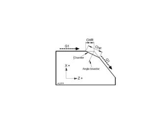
CornerValue
-
Function — CHAMFER / ROUND
-
Status — ACTIVE
-
Input —
- Text: Not Used
- Value: Length of chamfer or radius
When in CHAMFER mode, this macro defines the length from the programmed corner to the point at which the chamfer is to begin. In RADIUS mode, this defines the radius to be used in the corner. The start and end points of the arc will be calculated such that the arc is tangent to the cut coming into and out of the arc. In both cases, the original corner (as defined in the tool path) must be defined with two line segments.
CoupleAxisOff
-
Function — MISCELLANEOUS
-
Status — ACTIVE
-
Input —
- Text: Name of the master component
- Value: Not Used
Cancels the axis coupling established by CoupleAxisOn for the specified master component. After the coupling is turned off, any subsystem that was waiting while the coupled components moved should call UpdateAxisValues to synchronize its axis state.
Note — If an axis was inactivated when the coupling was turned on, reactivate it after calling this macro using ActivateAxis.
See also — CoupleAxisOn, CoupleCompNames, UpdateAxisValues, ActivateAxis
CoupleAxisOn
-
Function — MISCELLANEOUS
-
Status — ACTIVE
-
Input —
- Text: master_component_name slave_component_name
- Value: Not Used
CoupleAxisOn, CoupleAxisOff are used to control "coupling" of two motion axes, where commands to drive one axis, drives both axes. The first argument is the name of the master component, the second argument is the name of the slave component. After this call is made, any time the master component moves the corresponding delta movement will be applied to the slave. At this point, the feature is very limited. A master can have only one slave. Unpredictable results may occur if circle records are processed while in this mode.
Example — To have the X axis drive X and U, you would call the following macros. InActivateAxis OV=7 CoupleAxisOn OT= "X U" Note — Since the slave axis will now be driven by the master axis, the slave axis should no longer try to drive itself while in this mode. If the slave axis is not in a "WAIT" state (see sync motion), you will need to call "InactivateAxis".
CoupleCompNames
-
Function — MISCELLANEOUS
-
Status — ACTIVE
-
Input —
- Text: master_component_name slave_component_name ...
- Value: 1 for same direction, -1 for reverse direction
-
Comment — Added V8.2
-
Input —
- Text: master_component_name slave_component_name ...
- Value: 1 for same direction, -1 for reverse direction
CoupleCompNames turns on the "coupling" of two or more components. The concept is: as the master component moves, the delta motion will be applied to the slave component. With this macro, the following is supported:
-
The slave component does not need to be inactivated. The delta that the master moves will be added to the motion on the slave component. This is sometimes referred to as the “train” feature. A person on a train moves with the train, but can also move within the train.
-
The delta that the master moves can be applied in the reverse direction to the slave.
-
You can couple any number of components together. You can do this all at once, or in separate calls. For example, to couple (B and C) to A, you can call this macro once with the argument “A B C”, or you call it once with “A B” and then once with “A C”.
-
You can chain couplings together. Meaning. A can drive B and B can drive C.
-
The input factor is only applied when spindles are being coupled. A factor of 2 means that the slave will rotate twice as fast as the master. A factor of -1 means that the slave spindle rotates in the opposite direction. No other negative values are supported.
See also — UnCoupleCompNames
CoupleSpindleSpeedCompNames
-
Function — MISCELLANEOUS
-
Status — ACTIVE
-
Input —
- Text: Master_component_name Slave_component_name
- Value: 0 = Uncouple (default), 1 = Couple
-
Comment — Added V9.5
-
Input —
- Text: Master_component_name Slave_component_name
- Value: 0 = Uncouple (default), 1 = Couple
This macro turns on/off the coupling of the spindle speed between two spindle components. This macro is limited to 2 and only 2 components. You cannot couple 1 and 2, and then couple 2 and 3. Currently, the coupling corresponds to spindle speed only. The macro only sets up the coupling, it does not set any spindle attributes. After the macro is called, when the spindle speed is set for the master, the slave spindle speed will also be set. If the spindle speed is set on the slave, only the slave spindle speed will be set. In general, this should not be done.
Note — Although the spindle speed can be coupled using the CoupleCompName macro, this macro is the preferred approach. The advantage of this macro over CoupleCompName is that CoupleSpiindleSpeedCompNames supports CSS mode, and the Spindle Speed in the status window gets updated.
CsysComponentCheck
-
Function — MISCELLANEOUS
-
Status — ACTIVE
-
Input —
- Text: csys_name component_name [FULL]
- Value: matrix tolerance value
-
Comment — Added in V9.6.x
-
Input —
- Text: csys_name component_name [FULL]
- Value: matrix tolerance value
This macro checks if the specified CSYS and component orientation matches. If they do not match, an error will be given. If FULL is specified as the third argument, the check is on the orientation and position. Otherwise the check is only on the orientation.
Note — The specified tolerance is on the matrix value, not the angle. Typically, this should be around .000001.
CurveFitOnOff
-
Function — CURVE FIT
-
Status — OBSOLETE
-
Input —
- Text: Not Used
- Value: 0 = Off (Default), 1 = On
Curve fitting can be selectively turned on and off by embedded comments in the G-Code file being processed. The embedded comments must contain the exact text "TURN CURVE FIT ON" and "TURN CURVE FIT OFF". This macro can also be used to toggle curve fitting on/off. A value of "1" turns curve fitting ON and a value of "0" turns curve fitting Off. To use this macro, the text of two unique comments must be defined as a control words. The CurveFitOnOff macro with an override is associated with the ON and OFF message. CurveFitOnOff is ignored when curve fitting is not active..
Cut3dcMode
-
Function — CUTTER COMPENSATION
-
Status — ACTIVE
-
Input —
- Text: Not Used
- Value: 0 = Off (Default), 1 = On
-
Comment — Added 7.1
-
Input —
- Text: Not Used
- Value: 0 = Off (Default), 1 = On
This macro is used to turn "on", and "off", 3D cutter compensation logic to support the CUT3DC command in Siemens 840D controllers. The 3D cutter compensation mode is activated by calling this macro with Override Value =1. The 3D CUTCOM state is modal (it is NOT cancelled by the CutterCompOff macro) . It can only be cancelled by calling this macro with an Override Value = 0. As currently implemented, the 3D logic rides on top of of the 2D logic: to calculate CUTCOM offsets, the motion plane is internally changed to the tool axis plane, in which a left or right offset is performed. Circular motions work if the tool axis is perpendicular to the circle plane, otherwise an error is output.
CutterComp3d
-
Function — CUTTER COMPENSATION
-
Status — ACTIVE
-
Input —
- Text: Not Used
- Value: 1 = 3D compensation without a vector
-
1 = 3D compensation without a vector
- Any other value = 3D compensation specified with a vector
This macro turns on 3-D Cutter Compensation. Use an Override Value of "0" to specify that a vector is used to define the direction of the offset. This is the Default. Use an Override Value of "1" to specify that a vector is not used to specify the direction of the offset.
See Also — Tool3dXOffset, Tool3dYOffset, Tool3dZOffset, Unitize3DVector, CutterCompOff
CutterComp3dReversedWarnLevel
-
Function — CUTTER COMPENSATION
-
Status — ACTIVE
-
Input —
- Text: Not Used
- Value: 0/½
This macro is used to set the error/warning level for the "Cutter Compensated motion direction is reversed" message. This optional message is output when a 3D cutter compensation contour has a small linear motion in a reverse direction. The default value is 0, which outputs no messages. The value = 1 sets the output message type to WARN, and the value = 2 sets the output message type to ERROR.
CutterCompBottleneckDetect
-
Function — CUTTER COMPENSATION
-
Status — ACTIVE
-
Input —
- Text: Not used
- Value: 0 – no messages, 1 – error message (the default value), 2 – warning message
-
Comment — Added in V9.1
-
Input —
- Text: Not used
- Value: 0 – no messages, 1 – error message (the default value), 2 – warning message
When this macro is set to the error/warning level the message "Bottleneck condition: first and last motions are too close for this compensation value" is output when a bottleneck condition is detected. This macro is only applicable to the full mode of cutter compensation.
CutterCompConnectionType
-
Function — CUTTER COMPENSATION
-
Status — ACTIVE
-
Input —
- Text: Not Used
- Value: 1 = the circular connection type is set.
-
Comment — Added 8.0
-
Input —
- Text: Not Used
- Value:
- 0 = the linear connection type is set (default).
- 1 = the circular connection type is set.
The setting determines how outside corners are compensated. With the linear type the compensation is done by linear motions. With the circular type a circular motion is added around outside corners, the circle radius is the compensation value.
CutterCompConnectTypeSuspend
-
Function — CUTTER COMPENSATION
-
Status — ACTIVE
-
Input —
- Text: Not Used
- Value: Not Used
-
Comment — Added 9.2
-
Input —
- Text: Not Used
- Value: Not Used
If the current cutter comp connection type for outer corners is circular (set by CutterCompConnectionType with OV=1) then this macro resets it to linear for the current block, and it is restored to circular for the next block. If the current connection type is linear this macro has no effect.
CutterCompDoubleLong
-
Function — CUTTER COMPENSATION
-
Status — ACTIVE
-
Input —
- Text: Not Used
- Value: Not Used
Increases the movement amount by twice the tool offset value. The offset will be applied to each axis in which there is movement. (not modal)
See Also — ShortLongOffsetReset
CutterCompDoubleShort
-
Function — CUTTER COMPENSATION
-
Status — ACTIVE
-
Input —
- Text: Not Used
- Value: Not Used
Decreases the movement amount by twice the tool offset value. The offset will be applied to each axis in which there is movement. (not modal)
See Also — ShortLongOffsetReset
CutterCompFeedrateAdjust
-
Function — Cutter Compensation
-
Status — ACTIVE
-
Input —
- Text: Not used
- Value: 0 = Off (default)
-
0 = Off (default)
- 1 = On for inside cuts
- 2 = On for inside and outside cuts
This macro turns on/off the feature to automatically adjust the feed rate for circular arcs at inside and outside contours so that the feed rate at the tool cutting edge remains constant. This feature is only active when in cutter compensation mode, and the setting is modal.
This feature is used for time calculations only. Currently, this feature is not supported with optimization. This feature was originally implemented for Heidenhain TNC 640, M109, M110, and M111 commands.
CutterCompFlagShortMotion
-
Function — CUTTER COMPENSATION
-
Status — ACTIVE
-
Input —
- Value: tolerance value for detecting too short compensated motions
-
Comment — Added in V9.1
-
Input —
- Text: "warn" or "error", to indicate the type of messages this macro would trigger
- Value: tolerance value for detecting too short compensated motions
Use this macro to set the error/warning level and the tolerance for producing "Compensation value too large: motion block cannot be reached" messages on short compensated motion segments. This macro should be called after calling the CutterCompFull macro set with Override Value = 1. This macro is only applicable to cutter compensation full mode.
CutterCompFlipOnReversedToolAxis
-
Function — CUTTER COMPENSATION
-
Status — ACTIVE
-
Input —
- Text: Not Used
- Value: 0/1
This macro is used to turns on the flag that flips cutter compensation direction if tool axis is negative, i.e. is a reversed motion plane normal. The default value is 0, which sets the flag to OFF. The value = 1 sets the flag to ON. If the flag is ON: when we turn on cutter compensation we check if the current tool axis vector is negative, and if it is we perform LEFT <-> RIGHT flip of the programmed cutter compensation direction
CutterCompFull
-
Function — CUTTER COMPENSATION
-
Status — Active
-
Input —
- Text: Not Used
- Value: 0 = 1 block look ahead, 1 = full look ahead (Default)
-
Comment — Added V7.2
-
Input —
- Text: Not Used
- Value: 0 = 1 block look ahead, 1 = full look ahead (Default)
Use this macro to turn on and off full look-ahead mode for 2D cutter compensation. Use Override Value = 0 to turn off full look-ahead mode. Use Override Value = 1 to turn on full look ahead mode. This macro could be called at the start of processing, or for a specific cutter compensation motion.
CutterCompIgnoreEndGouge
-
Function — CUTTER COMPENSATION
-
Status — ACTIVE
-
Input —
- Text: Not Used
- Value: 1 = ON, 0 = OFF (default)
This macro expects one argument, the value of 0 or 1 If the value is 1 the flag is set to Ignore a possible gouge by the last pre-rampoff motion (i.e. to disregard the last motion when possible self-intersections of compensated contour are considered). This flag is only used with the full mode of cutter compensation. If the value is 0 the flag is reset, and the last motion is not ignored when possible self-intersections of compensated contour are considered.
CutterCompInterferenceAtStartWarning
-
Function — CUTTER_COMP
-
Status — ACTIVE
-
Input —
- Text: Not used
- Value: 1 = warning, 2 = error, anything else = OFF (default)
-
Comment — Added in V9.6.x
- Input —
- Text: Not used
- Value: 1 = warning, 2 = error, anything else = OFF (default)
This macro is used to check for “interference at start” condition for a cutter compensated contour; and output a warning or error if such condition is detected.
An interference is understood as an intersection of a cutter body (assuming a simple flat-end cutter of the radius equaling the compensation offset distance) with the subsequent programmed motions in the compensated contour. This happens for instance when the first compensated motion is a linear move shorter than the compensation offset distance.
When the macro is called, and an “interference at start” detected, a warning or error is output depending on the macro overwrite value.
This macro is modal and is designed to be called at Start of Processing.
CutterCompLeft
-
Function — CUTTER COMPENSATION
-
Status — ACTIVE
-
Input —
- Text: Not Used
- Value: Not Used
Turns on cutter compensation and sets the direction to Left — the cutter stays to the left of the programmed toolpath.
Notes —
- If the compensation amount is zero or the global cutter compensation switch is off, cutter compensation will not be activated.
- If single mirroring is active within the compensation plane, the direction is automatically reversed to Right.
See also — CutterCompRight, CutterCompOff, CutterCompFull, CutterCompValue
CutterCompLong
-
Function — CUTTER COMPENSATION
-
Status — ACTIVE
-
Input —
- Text: Not Used
- Value: Not Used
Increases the movement amount by the tool offset value. The offset will be applied to each axis in which there is movement. (not modal)
See Also — ShortLongOffsetReset
CutterCompLookAhead
-
Function — CUTTER COMPENSATION
-
Status — ACTIVE
-
Input —
- Text: Not Used
- Value: The number of look-ahead steps . (Default = 0)
-
Comment — Added V8.0
-
Input —
- Text: Not Used
- Value: The number of look-ahead steps . (Default = 0)
Use this macro to specify the number of look-ahead steps for the CutterCompFull macro with an Override Value of 1. The basic idea of look-ahead steps is: Vericut calculates the offsets for each motion segment, resolves the corners, and then eliminates self-intersections that occur within the specified number of steps. The default number of look-ahead steps is zero which means the whole contour.
CutterCompNegRadiusOK
-
Function — CUTTER COMPENSATION
-
Status — ACTIVE
-
Input —
- Text: Not Used
- Value: OV=1 is on; OV=0 is off
-
Comment — Added V8.0
-
Input —
- Text: Not Used
- Value: OV=1 is on; OV=0 is off
If the macro is on, “Cutter Compensation produced a negative error” message is suppressed. If off, the error is not suppressed.
CutterCompNoIntersect
-
Function — CUTTER COMPENSATION
-
Status — ACTIVE
-
Input —
- Text: Not Used
- Value: Not Used
-
Comment — Added V7.1.4
-
Input —
- Text: Not Used
- Value: Not Used
This macro turns off the intersection logic between the current motion and the next motion. Typically within the cutter compensation logic, we apply the cutter compensation, and then look for the intersection between the current compensated motion and the next compensated motion. Looking ahead for an intersection allows us to stop short on an inside wall. This macro turns off the intersection logic for the current motion. This macro was originally implemented for the G46 feature on a Delta Tau control
CutterCompOff
-
Function — CUTTER COMPENSATION
-
Status — ACTIVE
-
Input —
- Text: Not Used
- Value: Not Used
This macro is used to turn off cutter compensation.
See Also — CutterCompRight, CutterCompLeft and CutterComp3d
CutterCompOffAtTangentialExit
-
Function — CUTTER COMPENSATION
-
Status — ACTIVE
-
Input —
- Text: Not Used
- Value: 0 = Off
-
Comment — Added V8.0
-
Input —
- Text: Not Used
- Value: 0 = Off, 1 = On
This macro is used to set a special flag which ensures that any active cutter compensation is canceled at a tangential departure.
CutterCompOffHold
-
Function — CUTTER COMPENSATION
-
Status — OBSOLETE
-
Input —
- Text: Not Used
- Value: 0 = process G40 command with or without motion on line.
-
0 = process G40 command with or without motion on line.
- 1 = process G40 command with motion on line immediately or hold G40 command until line with motion is encountered.
CutterCompOffLookAheadX
-
Function — CUTTER COMPENSATION
-
Status — ACTIVE
-
Input —
- Text: Not Used
- Value: Coordinate value
Specify where the next XYZ point is on the part (not the next GOTO point). These macros are called while ramping off of cutter compensation. These values are used to avoid gouging the part while ramping off. Look ahead cutter compensation will use these values to determine if the previous compensated point needs to be adjusted.
CutterCompOffLookAheadY
-
Function — CUTTER COMPENSATION
-
Status — ACTIVE
-
Input —
- Text: Not Used
- Value: Coordinate value
Specify where the next XYZ point is on the part (not the next GOTO point). These macros are called while ramping off of cutter compensation. These values are used to avoid gouging the part while ramping off. Look ahead cutter compensation will use these values to determine if the previous compensated point needs to be adjusted.
CutterCompOffLookAheadZ
-
Function — CUTTER COMPENSATION
-
Status — ACTIVE
-
Input —
- Text: Not Used
- Value: Coordinate value
Specify where the next XYZ point is on the part (not the next GOTO point). These macros are called while ramping off of cutter compensation. These values are used to avoid gouging the part while ramping off. Look ahead cutter compensation will use these values to determine if the previous compensated point needs to be adjusted.
CutterCompOffsetValue
-
Function — CUTTER COMPENSATION
-
Status — ACTIVE
-
Input —
- Text: Not Used
- Value: Index into Cutter Compensation table
Uses the passed in numeric value as an index into the Cutter Compensation table (see the Tables for Processing G-Codes section, in the Vericut Help Library). The corresponding value (singular) is used when processing CDC short/long commands (e.g. G45-G48). For this macro to work, the G45-G48 word/value pairs must be found in the control configuration ahead of the XYZ registers. For example, try defining these word/addresses in the "States" supergroup.
CutterCompOffWarning
-
Function — CUTTER COMPENSATION
-
Status — ACTIVE
-
Input —
- Text: Not Used
- Value: OV = 1 produces warning message, OV=2 produces error message, OV=0 turns off macro
-
Comment — Added in V8.0
-
Input —
- Text: Not Used
- Value: OV = 1 produces warning message, OV=2 produces error message, OV=0 turns off macro
This macro is used to check for reverse motion at the end of compensation. If the OV=1, a warning message “Reverse motion on Cutter Compensation End” is generated if reverse motion is detected at the ramp-off motion. If the OV=2, the same message is produced but as an error message. If the OV=0 , the macro functionality is turned off. See CutterCompOnWarning for checking reverse motion at the start of compensation.
CutterCompOnOffSwitches
-
Function — CUTTER COMPENSATION
-
Status — ACTIVE
-
Input —
- Text: Specifies how to turn on/off cutter compensation.
- Value: Additional options specific to the Text option specified
-
Comment — Added V6.2.2
-
Input —
- Text: Specifies how to turn on/off cutter compensation.
- Value: Additional options specific to the Text option specified
Text = 1: - Value = 1 Ramp On - Value = 2 Immediate
Text = 2: - Value = 1 Ramp On with Active Plane Motion - Value = 2 Immediate - Value = 3 Ramp on with Any Motion
Text = 3: - Value = 1 Ramp On with Active Plane Motion - Value = 2 Immediate - Value = 3 Ramp On with Any Motion
Text = 11: - Value = 1 Adjusts the input coordinates to match the physical location of the tool. - Value = 2 Does not Adjust the input coordinates to match the physical location of the tool. - Value = 3 Sets the axis positions to match the last programmed point.
This macro is used to set the flags which determine how to process the turning on and turning off of Cutter Compensation.
CutterCompOnSkipFirst
-
Function — CUTTER COMPENSATION
-
Status — ACTIVE
-
Input —
- Text: Not Used
- Value: 1 = ON, anything else = OFF (default)
This macro expects 1 argument, the value of 0 or 1. If the value is 1 the flag is set to skip first offset position when cutter comp starts immediately. If the value is 0 the flag is reset, and the first offset position is processed when cutter comp starts immediately.
CutterCompOnWarning
-
Function — CUTTER COMPENSATION
-
Status — ACTIVE
-
Input —
- Text: Not Used
- Value: OV = 1 produces warning message, OV=2 produces error message, OV=0 turns off macro
-
Comment — Added in V8.0
-
Input —
- Text: Not Used
- Value: OV = 1 produces warning message, OV=2 produces error message, OV=0 turns off macro
This macro is used to check for reverse motion at the start of compensation. If the OV=1, a warning message “Reverse motion on Cutter Compensation End” is generated if reverse motion is detected at the ramp-off motion. If the OV=2, the same message is produced but as an error message. If the OV=0 , the macro functionality is turned off. See CutterCompOffWarning for checking reverse motion at the end of compensation.
CutterCompRampoffSkipLast
-
Function — CUTTER_COMP
-
Status — ACTIVE
-
Input —
- Text: Not used
- Value: 1 = ON, anything else = OFF (default)
-
Comment — Added in V9.6.x
- Input —
- Text: Not used
- Value: 1 = ON, anything else = OFF (default)
This macro is used to skip the last ramp-off motion when cutter compensation is configured to end at Ramp-Off under this condition:
The block where cutter compensation is turned off (typically G40 block) does not have a motion in the motion plane.
If the condition is satisfied and the macro is activated, we do not output a motion plane ramping-off motion on the compensation turn-off block. If there is any motion programmed at that last block, such as a vertical withdrawal, it is processed form the last offset point.
This macro is modal and is designed to be called at Start of Processing.
CutterCompRamponSkipFirst
-
Function — CUTTER_COMP
-
Status — ACTIVE
-
Input —
- Text: Not used
- Value: 1 = ON, anything else = OFF (default)
-
Comment — Added in V9.6.x
- Input —
- Text: Not used
- Value: 1 = ON, anything else = OFF (default)
This macro is used to skip the first ramp-on motion when cutter compensation is configured to start at Ramp-On under this condition:
The block where cutter compensation is turned on (typically G41/G42 block) contains a linear motion which does not actually move the machine.
If the condition is satisfied and the macro is activated, the first compensated motion is offset normally but the first motion skips the first offset point and goes directly to the second one.
This macro is modal and is designed to be called at Start of Processing.
CutterCompRapidSuspend
-
Function — CUTTER COMPENSATION
-
Status — ACTIVE
-
Input —
- Text: Not Used
- Value: 0 = Rapid motions will be compensated. (Default)
-
Comment — Added V8.0
-
Input —
- Text: Not Used
- Value:
- 0 = Rapid motions will be compensated. (Default)
- 1 = Cutter compensation suspended for rapid motions.
When the value is set to 1, the rapid motion segments that occur during cutter compensation will not be compensated (i.e. cutter compensation will be suspended on rapid motions). When the value is 0, which is the default setting, rapid motion will be compensated the same as a non-rapid motion.
CutterCompRight
-
Function — CUTTER COMPENSATION
-
Status — ACTIVE
-
Input —
- Text: Not Used
- Value: Not Used
Turns on cutter compensation and sets the direction to Right — the cutter stays to the right of the programmed toolpath.
Notes —
- If the compensation amount is zero or the global cutter compensation switch is off, cutter compensation will not be activated.
- If single mirroring is active within the compensation plane, the direction is automatically reversed to Left.
See also — CutterCompLeft, CutterCompOff, CutterCompFull, CutterCompValue
CutterCompShort
-
Function — CUTTER COMPENSATION
-
Status — ACTIVE
-
Input —
- Text: Not Used
- Value: Not Used
Decreases the movement amount by the tool offset value. The offset will be applied to each axis in which there is movement. (not modal)
See Also — ShortLongOffsetReset
CutterCompShortCorner
-
Function — CUTTER_COMP
-
Status — ACTIVE
-
Input —
- Text: Not used
- Value: Not used
-
Comment — Added in V9.6.x
- Input —
- Text: Not used
- Value: Not used
This macro is used to set the special “short corner” condition on a block within the compensated contour.
When called, the next compensated motion point will be calculated as if the compensation were suspended for the last motion.
After the point has been calculated the following compensated motion points will be processed normally.
It could be described as a one-point suspended compensation: the compensation on the next motion block is suspended, but only to calculate the next compensated motion point.
This macro is NOT modal.
It is designed to be applied for a vertical motion within cutter compensation
CutterCompStartStopType
-
Function — CUTTER COMPENSATION
-
Status — ACTIVE
-
Input —
- Text: Not Used
- Value: OV = 1 is on; OV = 0 is off
-
Comment — Added in V8.0
-
Input —
- Text: Not Used
- Value: OV = 1 is on; OV = 0 is off
This macro can be effective only when the On/Off method is Ramp On/Off. It is designed to support the Fanuc “type B” option for the starting and ending of cutter compensation. If the setting is On the outside corners formed by Ramp On/Off motions are compensated; if the setting is Off such outside corners are not compensated
CutterCompSuspend
-
Function — CUTTER COMPENSATION
-
Status — ACTIVE
-
Input —
- Text: Not Used
- Value: Not Used
Temporarily suspends radius compensation for one block. This macro was implemented to support the Heidenhain M98 command.
Note — It must be called with Process after Motion toggled off (not checked). Refer to Add/Modify Word/Address window in the Vericut Help section, in the Vericut Help Library for more information.
CutterCompTBD
-
Function — CUTTER_COMPENSATION
-
Status — ACTIVE
-
Input —
- Text: Not Used
- Value: Not Used
-
Comment — Added V7.1.6
-
Input —
- Text: Not Used
- Value: Not Used
This macro is used to simulate a G46 command in a Traub TX8 control. The G46 command is an auto detection cutter compensation direction. It looks ahead to see the path and then looks at the tool tip type to determine if it should be cutter comp left or cutter comp right. This macro turns Cutter Compensation On but does not set the left/right direction until there are two motions in the queue. Then if these two motions form a left turn Vericut sets the compensation direction to "left", and if the two motions form a right turn Vericut sets the cutter compensation direction to "right".
CutterCompToolNum
-
Function — CUTTER COMPENSATION
-
Status — OBSOLETE
-
Input —
- Text: None
- Value: None
-
Comment — Use ToolCutterComp
CutterCompToolNumSubValue
-
Function — CUTTER COMPENSATION
-
Status — OBSOLETE
-
Input —
- Text: None
- Value: None
-
Comment — Use ToolCutterComp
CutterCompValue
-
Function — CUTTER COMPENSATION
-
Status — OBSOLETE
-
Input —
- Text: None
- Value: None
-
Comment — Use ToolCutterComp
CutterCompValueCombo
-
Function — CUTTER COMPENSATION
-
Status — ALTERNATE
-
Input —
- Text: Not Used
- Value: Index Value
-
Comment — Added V7.1.3
- Originally intended for just the NUM controller
-
Input —
- Text: Not Used
- Value: Index Value
This macro uses the numeric value that is passed in as an index into the Cutter Compensation table (ref. Cutter Compensation Table in the Tables for Processing G-Codes section, in the Vericut Help Library). The values for SubRegister 1 and 2 will be added together and the total will be used when in cutter compensation mode (e.g. G51, G42).
Note — This macro only references the Cutter Compensation table, and does not reference the TLS file. Therefore, this macro, although new, is seen as OBSOLETE except for the NUM control.
CutterCompValueDirect
-
Function — CUTTER COMPENSATION
-
Status — ACTIVE
-
Input —
- Text: Not Used
- Value: Cutter compensation value
This macro is used to set the cutter compensation value to the input value. The specified value is used as the compensation amount when CDC is turned on.
CutterCompValueWarning
-
Function — CUTTER COMPENSATION
-
Status — ACTIVE
-
Input —
- Text: Not Used
- Value: 0 = No Warning or Error messages output (Default)
-
Comment — Added V7.3.1
-
Input —
- Text: Not Used
- Value:
- 0 = No Warning or Error messages output (Default)
- 1 = messages output as Warnings
- 2 = messages output as Errors
This macro enables you to specify how you want unreachable motion segments reported. Set Override Value = 0 (Default) to have no Warning messages or Error messages output when unreachable motion segments are encountered. Set Override Value = 1 to have messages output as Warnings when unreachable motion segments are encountered. Set Override Value = 2 to have messages output as Errors when unreachable motion segments are encountered.
This macro should be called after calling the CutterCompFull macro set with Override Value = 1. This macro is only applicable to cutter compensation full mode.
One of the following messages will be output when unreachable motion segments are encountered:
-
"Compensation value too large: cannot offset circle with radius = r" or
-
"Compensation value too large: motion block cannot be reached."
CutWire
-
Function — WIRE EDM
-
Status — ACTIVE
-
Input —
- Text: Not Used
- Value: Not Used
Cut/remove the EDM wire. This will output a "LOADTL/0" statement.
CycleAxis
-
Function — DRILL CYCLES
-
Status — ACTIVE
-
Input —
- Text: Cycle axis register (X, Y, Z, U, V, W, U2, V2, or W2)
- Value: Not Used
-
Comment — Added V6.2
-
Input —
- Text: Cycle axis register (X, Y, Z, U, V, W, U2, V2, or W2)
- Value: Not Used
This macro specifies the component (by register) to use while processing drill cycles.
Example — If “V” is specified, and V travels along the Z axis, then the V component will be used for stroking along Z.
Note — Stroking is always done along the tool axis, which may contain motions along the X, Y, and Z axis.
CycleBoreBottomRetractDist
-
Function — DRILL CYCLES
-
Status — ACTIVE
-
Input —
- Text: Not used
- Value: Distance
-
Comment — Added in 9.4
-
Input —
- Text: Not used
- Value: Distance
For Bore Drill cycles, after reaching the bottom, if the third CycleBoreShiftFlags is set to -1, this macro specifies the distance move up before shifting the tool in. This motion up is important in order that the insert doesn’t create a drag mark on the bottom surface. This macro is only applicable to the Boring Drill cycles.
CycleBoreShiftAxis
-
Function — DRILL CYCLES
-
Status — ACTIVE
-
Input —
- Text: X, Y, or Z (default = X)
- Value: Not used
-
Comment — Added in V8.2
-
Input —
- Text: X, Y, or Z (default = X)
- Value: Not used
For Bore Drill cycles, at various point in the cycle, a shift is applied. This macro specifies with tool axis the shift is to be applied. This value is modal. This macro is only applicable to the CyclesBore, CyclesBoreDrag, and CyclesBoreOrient macros.
CycleBoreShiftFlags
-
Function — DRILL CYCLES
-
Status — ACTIVE
-
Input —
- Text: Shift flags
- Value: Not Used
The boring cycles support 5 areas in which a shift may occur.
These are:
-
Value 1: Prior to beginning the drill cycle
-
Value 2: After moving to the R plane
-
Value: After moving to the "bottom" position
-
Value 4: After moving back to the R plane
-
Value 5: After moving back to the retract position
-
This macro is passed 5 values (each representing one of the possible shift areas as indicated above), separated by blank spaces, in the Override Text field. These 5 values specify whether a shift should occur, and the direction of the shift.
-
0 = No Shift
-
1 = Shift Positive Direction
-
1 = Shift Negative Direction
-
For a simple boring cycle, the Override Text value might look like: 0 0 -1 0 1
-
For a back boring cycle, the Override Text value might look like: -1 1 -1 0 1
-
This macro is only applicable to the CyclesBore, CyclesBoreDag), and CyclesBoreOrient macros.
CycleBoreShiftValue
-
Function — DRILL CYCLES
-
Status — ACTIVE
-
Input —
- Text: Not Used
- Value: Length of the shift
This macro is passed a positive value corresponding to the length of the shift that should be applied during boring cycles. This shift will occur along the tools X axis (as defined in Tool Manager prior to any orientation matrix). The axis that the shift is to be applied is specified with the CycleBoreShiftAxis macro (default to Tool's X axis). This macro is only applicable to the CyclesBore, CyclesBoreDag), and CyclesBoreOrient macros.
CycleBoreSpindleOnOffFlags
-
Function — DRILL CYCLES
-
Status — ACTIVE
-
Input —
- Text: Spindle On/Off flags for 10 different positions
- Value: Not Used
This command specifies the spindle condition in 10 different positions. The positions are: either side of the shifts defined in the CycleBoreShiftFlags macro. These values are:
-
Value 1: Prior to first shift – Initial state
-
Value 2: After the first shift
-
Value 3: After moving to R Plane and before the second shift
-
Value 4: After second shift
-
Value 5: After moving to the bottom, and before the third shift
-
Value 6: After the third shift
-
Value 7: After moving back to the R Plane and before the fourth shift
-
Value 8: After the fourth shift
-
Value 9: After moving back to the retract position and before the fifth shift
-
Value 10: After the fifth shift
-
This macro is passed 10 values (each representing one of the possible spindle condition areas as indicated above), separated by blank spaces, in the Override Text field. These 10 values specify whether a spindle condition should occur.
-
0 = Spindle Off
-
1 = Spindle On
-
For a simple boring cycle, the Override Text value might look like: 1 1 1 1 0 0 0 0 0 1
Note — - This command will turn on and off the spindle that has been set with the SpindleCompName macro.
- This macro is only applicable to the CyclesBore, CyclesBoreDrag, and CyclesBoreOrient macros.
CycleClearanceDistance
-
Function — DRILL CYCLES
-
Status — OBSOLETE
-
Input —
- Text: None
- Value: None
CycleDepth
-
Function — DRILL CYCLES
-
Status — ACTIVE
-
Input —
- Text: Not Used
- Value: Depth value
This macro is used to set the Cycle Depth value.
CycleDepthInv
-
Function — DRILL CYCLES
-
Status — ACTIVE
-
Input —
- Text: Not Used
- Value: Depth value
If the Cycle Depth is to be interpreted as an absolute value, the Cycle Depth value is set to the input value. If the Cycle Depth is to be interpreted as an incremental value, the Cycle Depth value is set to the negated input value.
CycleDepthType
-
Function — DRILL CYCLES
-
Status — ACTIVE
-
Input —
- Text: Not Used
- Value: 1 = Absolute value
-
1 = Absolute value
- 2 = Incremental value
- 3 = G-Code dependent
This macro is used to specify how the Cycle Depth is to be interpreted.
CycleDrillingAxisLogic
-
Function — DRILL CYCLES
-
Status — ACTIVE
-
Input —
- Text: Not used
- Value: - 0 = drilling axis based on Tool’s Z axis (default)
-
Comment — Added in V[#]
-
Input —
- Text: Not used
- Value:
- 0 = drilling axis based on Tool’s Z axis (default)
- 1 = drilling axis based on the axis perpendicular to the local motion plane
This macro specifies whether the drilling axis is determined by the Tool’s Z axis or perpendicular to the motion plane. This macro was introduced to support:
-
Controls which have 3D drill cycles that are independent of the motion plane.
-
Controls which have bit switches that determine if the drilling axis is based on the motion plane.
CycleDwellTime
-
Function — DRILL CYCLES
-
Status — ACTIVE
-
Input —
- Text: Not Used
- Value: Dwell time
This macro is used to specify the dwell time for a cycle. Dwell time is measure in revolutions or seconds (dependent on the feed mode).
CycleFeedCheckOnOff
-
Function — DRILL CYCLES
-
Status — ACTIVE
-
Input —
- Text: Not Used
- Value: 0 = Turns off error message, 1 = Turns on error message (Default)
-
Comment — Added V7.0.1
-
Input —
- Text: Not Used
- Value: 0 = Turns off error message, 1 = Turns on error message (Default)
Internally Vericut converts the cycle parameters into distance to "RAPID TO" and distance to "FEED TO", measured from the part surface, and measured along the Tool's Z axis. If the "FEED TO" value is larger then the "RAPID TO" value, and this is not a back boring operation, then Vericut reports an error. This macro is used to turn this error message on and off. A value of zero turns the error message "off", and a value of 1 turns the error message "on". The default is on.
Note — This error should only be turned off in very rare situations.
CycleFeedMode
-
Function — DRILL CYCLES
-
Status — ACTIVE
-
Input —
- Text: Not Used
- Value: 1 = FPM (default), 2 = Feedmode
-
Comment — Added V9.5x
-
Input —
- Text: Not Used
- Value: 1 = FPM (default), 2 = Feedmode
Depending on the Feed mode (FPM or FPR), Vericut will check the current feedrate to see if it should be considered a Fast Feed. It will use either the “Fast Feed per Min” value or the “Fast Feed per Rev” value. These values are on the Configure Setup panel. Traditionally, drill cycles were always considered FPM when applying this check. Calling this macro with a value of 2 will cause the drill cycles to use the current Feed mode when applying this check. This macro would typically be called during Start of Processing.
CycleIgnore
-
Function — DRILL CYCLES
-
Status — ACTIVE
-
Input —
- Text: Not Used
- Value: Not Used
This macro is used to set a flag which causes the cycle to not be executed on the current block.
CycleIncDepthType
-
Function — DRILL CYCLES
-
Status — OBSOLETE
-
Input —
- Text: None
- Value: None
CycleIncRapidType
-
Function — DRILL CYCLES
-
Status — OBSOLETE
-
Input —
- Text: None
- Value: None
CycleInitialOnMotion
-
Function — DRILL CYCLES
-
Status — ACTIVE
-
Input —
- Text: Not Used
- Value: 0 = FALSE (Default), 1 = TRUE
This macro is used to specify whether the cycle "Initial Point" should be initialized on each motion.
CycleMillCenterAbscissa
-
Function — THREAD MILL CYCLES
-
Status — ACTIVE
-
Input —
- Text: Not Used
- Value: Abscissa value
-
Comment — Added V6.1
-
Input —
- Text: Not Used
- Value: Abscissa value
This macro is used to enter the abscissa (the component of the point along the horizontal axis) for milled threads in the active motion plane.
CycleMillCenterOrdinate
-
Function — THREAD MILL CYCLES
-
Status — ACTIVE
-
Input —
- Text: Not Used
- Value: Ordinate value
-
Comment — Added V6.1
-
Input —
- Text: Not Used
- Value: Ordinate value
This macro is used to enter the ordinate (the component of the point along the vertical axis) for milled threads in the active motion plane.
CycleMillPocketAbsDepth
-
Function — POCKET CYCLES
-
Status — ACTIVE
-
Input —
- Text: Not Used
- Value: Depth value
-
Comment — Added V7.2.3
-
Input —
- Text: Not Used
- Value: Depth value
Sets the absolute depth for the pocket based on the active Program Zero.
CycleMillPocketAngle
-
Function — POCKET CYCLES
-
Status — ACTIVE
-
Input —
- Text: Not Used
- Value: Rotation angle
This macro is used to set the rotation angle, in degrees, with respect to the positive X-axis for a rectangular pocket.
CycleMillPocketBottomAllowance
-
Function — POCKET CYCLES
-
Status — ACTIVE
-
Input —
- Text: Not Used
- Value: Allowance value
This macro is used to specify the amount of bottom stock to remain after roughing motions. The remaining bottom stock is removed during finishing motions.
See Also — CycleMillPocketSideAllowance
CycleMillPocketBottomZ
-
Function — POCKET CYCLES
-
Status — ACTIVE
-
Input —
- Text: Not Used
- Value: Depth value
This macro is used to set the depth for the pocket specified by a Z-axis position.
CycleMillPocketBoundarySub
-
Function — POCKET CYCLES
-
Status — ACTIVE
-
Input —
- Text: Text name of the subroutine
- Value: Numeric name of the subroutine.
This macro is used to specify the subroutine number used to define the pocket's boundary. The macro CycleMillPocketType must be used with an Override Value of 2 when a subroutine defines the pocket boundary. The name that is used (Text or Value) is dependent on the “Type of Subroutine Names” switch.
CycleMillPocketCenterCurrentX
-
Function — POCKET CYCLES
-
Status — ACTIVE
-
Input —
- Text: Not Used
- Value: Not Used
-
Comment — Added V7.4.2
-
Input —
- Text: Not Used
- Value: Not Used
These macros use the current tool position to specify the center (or drill hole) location for a rectangular or circular milled pocket.
CycleMillPocketCenterCurrentY
-
Function — POCKET CYCLES
-
Status — ACTIVE
-
Input —
- Text: Not Used
- Value: Not Used
-
Comment — Added V7.4.2
-
Input —
- Text: Not Used
- Value: Not Used
These macros use the current tool position to specify the center (or drill hole) location for a rectangular or circular milled pocket.
CycleMillPocketCenterX
-
Function — POCKET CYCLES
-
Status — ACTIVE
-
Input —
- Text: Not Used
- Value: Center position
This macro is used to specify the center (or drill hole) location for a rectangular or circular milled pocket.
Note — Controls that use the current tool location for the pockets center do not need to reference these macros.
CycleMillPocketCenterY
-
Function — POCKET CYCLES
-
Status — ACTIVE
-
Input —
- Text: Not Used
- Value: Center position
This macro is used to specify the center (or drill hole) location for a rectangular or circular milled pocket.
Note — Controls that use the current tool location for the pockets center do not need to reference these macros.
CycleMillPocketCircleCuttingRapid
-
Function — POCKET CYCLES
-
Status — ACTIVE
-
Input —
- Text: Not Used
- Value: 0 = G1 start/end linear motions (default)
-
Comment — Added V8.0
-
Input —
- Text: Not Used
- Value:
- 0 = G1 start/end linear motions (default)
- 1 = G0 start/end linear motion
This macro is used to turn On/Off rapid for the start/end linear motion of a pocket circle cutting cycle.
CycleMillPocketCornerRadius
-
Function — POCKET CYCLES
-
Status — ACTIVE
-
Input —
- Text: Not Used
- Value: Radius value
This macro sets the corner radius for a rectangular pocket and the major radius for a circular pocket. Default is tool radius.
CycleMillPocketCutDirection
-
Function — POCKET CYCLES
-
Status — ACTIVE
-
Input —
- Text: [SIGN]
- Value: If SIGN specified: Positive = Conventional (CLW)
-
If SIGN specified: Positive = Conventional (CLW), Negative = Climb (CCLW)
- If SIGN not specified: 0 or 2 = Conventional (CLW), 1 or 3 = Climb (CCLW)
This macro sets the cut direction for conventional or climb milling. Also sets cut direction for circular pockets to CLW or CCLW.
CycleMillPocketCutType
-
Function — POCKET CYCLES
-
Status — ACTIVE
-
Input —
- Text: Not Used
- Value: 0 = a lacing pattern (climb and conventional)
-
0 = a lacing pattern (climb and conventional)
- 1 = single direction conventional cuts with retracts between cuts
- 2 = a lacing pattern with finish cuts
- 3 = an inside-out pattern
- 4 = finish bottom and sides (no roughing).
This macro is used to specify the type of motions for the pocket.
Note — Use macro SiemensCycleMillPocketCutType for Siemens controls.
CycleMillPocketDepth
-
Function — POCKET CYCLES
-
Status — ACTIVE
-
Input —
- Text: Not Used
- Value: Relative Depth of the pocket
This macro sets the relative depth for the pocket from top of the stock to bottom of the pocket.
CycleMillPocketDepthSigned
-
Function — POCKET CYCLES
-
Status — ACTIVE
-
Input —
- Text: Not Used
- Value: Signed Relative Depth of the pocket
-
Comment — Added V9.6.3
-
Input —
- Text: Not Used
- Value: Signed Relative Depth of the pocket
Description —
This macro sets the signed relative depth for the pocket from top of the stock to bottom of the pocket.
CycleMillPocketFinishFeed
-
Function — POCKET CYCLES
-
Status — OBSOLETE
-
Input —
- Text: None
- Value: None
CycleMillPocketFinishStepover
-
Function — POCKET CYCLES
-
Status — ACTIVE
-
Input —
- Text: Not Used
- Value: Depth of each pocket cut
This macro sets the X or Y in-feed between finishing pocket cuts.
CycleMillPocketInsideRadius
-
Function — POCKET CYCLES
-
Status — ACTIVE
-
Input —
- Text: Not Used
- Value: Inside Radius
This macro sets an inside radius for circular pockets when a pre-drilled hole at the pocket center is used. Default is zero.
CycleMillPocketLength
-
Function — POCKET CYCLES
-
Status — ACTIVE
-
Input —
- Text: Not Used
- Value: Length of a rectangular pocket
This macro sets the length along the X-axis for a rectangular milled pocket.
CycleMillPocketLoopCount
-
Function — POCKET CYCLES
-
Status — ACTIVE
-
Input —
- Text: Not Used
- Value: Loop count
-
Comment — Added V7.3
-
Input —
- Text: Not Used
- Value: Loop count
The loop cycle repeats a sequence of cut motions while feeding into the stock until the loop count is completed. Use this macro to set the number of times that the motions are offset and repeated.
CycleMillPocketMaxCutDepth
-
Function — POCKET CYCLES
-
Status — ACTIVE
-
Input —
- Text: Not Used
- Value: Maximum in-feed depth
This macro sets the maximum in:feed depth for each pocket level until final pocket depth is reached.
CycleMillPocketPlungeFeed
-
Function — POCKET CYCLES
-
Status — ACTIVE
-
Input —
- Text: Not Used
- Value: Feedrate
This macro sets the in-feed feedrate along the Z-axis for plunging into the material.
CycleMillPocketRefPlane
-
Function — POCKET CYCLES
-
Status — ACTIVE
-
Input —
- Text: Not Used
- Value: Z axis value
This macro sets the absolute Z-axis position for the top of the pocket stock.
CycleMillPocketRefPlaneDelta
-
Function — POCKET CYCLES
-
Status — ACTIVE
-
Input —
- Text: Not Used
- Value: Signed Z axis Value
-
Comment — Added V9.6.3
-
Input —
- Text: Not Used
- Value: Signed Z axis Value
Description —
This macro sets the signed delta Z-axis position for the top of the pocket stock.
CycleMillPocketRetractOnOff
-
Function — POCKET CYCLES
-
Status — ACTIVE
-
Input —
- Text: Not Used
- Value: 0 = do not retract
-
Comment — Added V7.3.3
-
Input —
- Text: Not Used
- Value: 0 = do not retract, 1 = retract (default)
This macro is used to turn On/Off the Retract option for milling pocket cycles.
CycleMillPocketRetractPlane
-
Function — POCKET CYCLES
-
Status — ACTIVE
-
Input —
- Text: Not Used
- Value: Z axis value
This macro sets the absolute Z-axis position where cycle motions will start and end.
CycleMillPocketRoughFeed
-
Function — POCKET CYCLES
-
Status — ACTIVE
-
Input —
- Text: Not Used
- Value: Feedrate
This macro sets the cutting feedrate for roughing pocket motions. Defaults to last feedrate in effect when cycle is called.
CycleMillPocketSafeDistance
-
Function — POCKET CYCLES
-
Status — ACTIVE
-
Input —
- Text: Not Used
- Value: Distance
This macro sets the distance above the pocket stock to the retract plane.
CycleMillPocketSafeDistanceSigned
-
Function — POCKET CYCLES
-
Status — ACTIVE
-
Input —
- Text: Not Used
- Value: Signed Distance
-
Comment — Added V9.6.3
-
Input —
- Text: Not Used
- Value: Signed Distance
Description —
This macro sets the signed distance above the pocket stock to the retract plane.
CycleMillPocketSideAllowance
-
Function — POCKET CYCLES
-
Status — ACTIVE
-
Input —
- Text: Not Used
- Value: Allowance
This macro sets the amount of side stock to remain after roughing motions. The remaining side stock is removed during finishing motions.
See Also — CycleMillPocketBottomAllowance
CycleMillPocketSpeed
-
Function — POCKET CYCLES
-
Status — ACTIVE
-
Input —
- Text: Not Used
- Value: Spindle Speed
Sets the spindle speed used with the pocket cutting motions.
CycleMillPocketStepover
-
Function — POCKET CYCLES
-
Status — ACTIVE
-
Input —
- Text: PERCENT, X, or Y
- Value: Step over amount in X or Y, or percentage of tool diameter
This macro sets the X or Y in-feed between roughing pocket cuts. When used with an Override Text value of PERCENT, the value passed is defined as a percent of the tool diameter and the step-over is calculated as a percentage of the current tool diameter. Use an Override Text value of X, or Y, with the HAAS control to define the cut stroking direction.
CycleMillPocketToolRadiusLogic
-
Function — POCKET CYCLES
-
Status — ACTIVE
-
Input —
- Text: Not Used
- Value: 1 = Uses existing logic (default) , 2 = Use the Cutter Comp Value
-
Comment — Added V9.5x
-
Input —
- Text: Not Used
- Value: 1 = Uses existing logic (default) , 2 = Use the Cutter Comp Value
This macro determines the logic that the CycleMillPocket software uses for its cutter compensation logic. This macro would typically be called during Start of Processing.
If this macro is called with the value set to 1:
-
If SetDynamicVars was called with CurCDC, get the value from the variable that this call sets. NOTE: This variable is set to the cutter comp value, and is set during BlockFinish.
-
Otherwise, uses the Tool radius.
If this macro is called with the value set to 2:
- The cutter comp value will be used.
CycleMillPocketType
-
Function — POCKET CYCLES
-
Status — ACTIVE
-
Input —
- Text: [AS_COMMANDED]
- Value: 0 = rectangular,
-
0 = rectangular
- 1 = circular
- 2 = boundary is defined in a subroutine.
- 3 = circular with support for cutter compensation.
- 4 = Heidenhain Pilot G841 (Roughing)
- 5 = Heidenhain Pilot G845 (Roughing)
- 6 = Heidenhain Pilot G840 (Roughing)
- 12 = Fanuc G12.2 Full circle cutting (clockwise)
- 13 = Fanuc G13.2 Full circle cutting (counterclockwise)
Selects the type of pocket and processes the cutting motions. The CycleMillPocketType macro must be called after all other pocket parameter macros have been called. The HAAS control uses a subroutine to define the pocket boundary.
Use an Override Value of 2 for the HAAS control.
Use an Override Value of 3 for controls where the circular pocket cycle does not automatically compensate for the cutter radius value; the final diameter is adjusted by the active Cutter Compensation value.
Use an Override Text value of "AS_COMMANDED" to execute the pockets from a "CALL CYCL" command. The default for the CycleMillPocketType macro is to execute the pocket when this macro is processed. When the override is present, the cycles are later executed AS_COMMANDED.
Use an Override Value of 4 for Heidenhain Pilot G841 (Roughing)
Use an Override Value of 5 for Heidenhain Pilot G845 (Roughing)
Use an Override Value of 6 for Heidenhain Pilot G840 (Roughing)
Use an Override Value of 12 for Fanuc G12.2 Full circle cutting (clockwise)
Use an Override Value of 13 for Fanuc G13.2 Full circle cutting (counterclockwise)
CycleMillPocketWidth
-
Function — POCKET CYCLES
-
Status — ACTIVE
-
Input —
- Text: Not Used
- Value: Width of a rectangular pocket
This macro sets the width along the Y-axis for a rectangular milled pocket.
CycleMillThread
-
Function — THREAD MILL CYCLES
-
Status — ACTIVE
-
Input —
- Text: Not Used
- Value: 0 = Female Thread (hole/inside), 1 = Male Thread (post/outside)
-
Comment — Added V6.1
-
Input —
- Text: Not Used
- Value: 0 = Female Thread (hole/inside), 1 = Male Thread (post/outside)
This macro activates a thread milling cycle. It must be called after all parameters are set or with the after motion option.
CycleMillThreadDir
-
Function — THREAD MILL CYCLES
-
Status — ACTIVE
-
Input —
- Text: Not Used
- Value: 2 = Clockwise (Default), 3 = Counterclockwise
-
Comment — Added V6.1
-
Input —
- Text: Not Used
- Value: 2 = Clockwise (Default), 3 = Counterclockwise
This macro is used to specify the direction for milled threads. Value is 2 for CW or 3 for CCLW (defaults to 2 if not specified).
CycleMillThreadFeed
-
Function — THREAD MILL CYCLES
-
Status — ACTIVE
-
Input —
- Text: Not Used
- Value: Feedrate
-
Comment — Added V6.1
-
Input —
- Text: Not Used
- Value: Feedrate
This macro is used to specify the feedrate for milled threads.
CycleMillThreadID
-
Function — THREAD MILL CYCLES
-
Status — ACTIVE
-
Input —
- Text: Not Used
- Value: Inside Diameter
-
Comment — Added V6.1
-
Input —
- Text: Not Used
- Value: Inside Diameter
This macro is used to specify the nominal inside diameter of the thread. (See Siemens 840D CYCLE90 documentation)
CycleMillThreadOD
-
Function — THREAD MILL CYCLES
-
Status — ACTIVE
-
Input —
- Text: Not Used
- Value: Outside Diameter
-
Comment — Added V6.1
-
Input —
- Text: Not Used
- Value: Outside Diameter
This macro is used to specify the nominal outside diameter of the thread. (See Siemens 840D CYCLE90 documentation)
CycleMillThreadPitch
-
Function — THREAD MILL CYCLES
-
Status — ACTIVE
-
Input —
- Text: Not Used
- Value: Thread pitch
-
Comment — Added V6.1
-
Input —
- Text: Not Used
- Value: Thread pitch
This macro is used to specify a milled thread pitch.
CycleMillThreadToolTeeth
-
Function — THREAD MILL CYCLES
-
Status — ACTIVE
-
Input —
- Text: Not Used
- Value: Number of Teeth on the tool (Default = 1)
-
Comment — Added V6.1
-
Input —
- Text: Not Used
- Value: Number of Teeth on the tool (Default = 1)
This macro is used to specify the milled thread count of teeth on tool. Some tools cut several threads per revolution. This count allows the cycle to adjust the depth accordingly.
CycleMotionPlaneCheckOnOff
-
Function — DRILL CYCLES
-
Status — ACTIVE
-
Input —
- Text: Not Used
- Value: 0 = Off (Default), 1 = ON
This macro turns on and off the error checking of the tool axis being along the Z-axis of the local plane when a cycle is executed. XY plane: Tool should be along the local Z axis YZ plane: Tool should be along the local X axis ZX plane: Tool should be along the local Y axis
Note — Not all controls require this. Therefore, this error checking must be turned on. By default, it is off.
CycleNormalInverse
-
Function — DRILL CYCLES
-
Status — ACTIVE
-
Input —
- Text: Not Used
- Value: 0 = do not invert, 1 = invert
The Drill Cycle normal is typically defined by the motion plane.
Example — If we are in the XY motion plane, than the Z axis of the local CSYS defines the Drill Cycle Normal. If this Drill Cycle Normal is going the opposite direction of what we need, this macro can be used to invert the direction of the normal. It is expected that this macro would rarely need to be used.
Note — Any drill cycle parameter that is specified as an incremental distance, the distance is measure along the cycle normal. If you invert the cycle normal, you should check the whether or not any of the drill cycle parameters needs to be inverted.
CyclePresentAxis
-
Function — MAPPING
-
Status — OBSOLETE
-
Input —
- Text: None
- Value: None
CycleRapidLevelInitial
-
Function — DRILL CYCLES
-
Status — OBSOLETE
-
Input —
- Text: None
- Value: None
CycleRapidLevelInv
-
Function — DRILL CYCLES
-
Status — OBSOLETE
-
Input —
- Text: None
- Value: None
CycleRapidLevelKeep
-
Function — DRILL CYCLES
-
Status — ACTIVE
-
Input —
- Text: Not Used
- Value: Not Used
This macro is called to apply the cycle rapid level instated via the CycleRapidLevelValue macro to cycles executed on command. This macro must be called during initialization ("Start of Processing" event).
CycleRapidLevelValue
-
Function — DRILL CYCLES
-
Status — OBSOLETE
-
Input —
- Text: None
- Value: None
CycleRapidLevelValueMult
-
Function — DRILL CYCLES
-
Status — OBSOLETE
-
Input —
- Text: None
- Value: None
CycleRapidLevelZeroTracking
-
Function — DRILL CYCLES
-
Status — OBSOLETE
-
Input —
- Text: None
- Value: None
CycleRapidType
-
Function — DRILL CYCLES
-
Status — OBSOLETE
-
Input —
- Text: None
- Value: None
CycleRetractInitial
-
Function — DRILL CYCLES
-
Status — OBSOLETE
-
Input —
- Text: None
- Value: None
CycleRetraction
-
Function — DRILL CYCLES
-
Status — OBSOLETE
-
Input —
- Text: None
- Value: None
CycleRetractSpecifiedpoint
-
Function — DRILL CYCLES
-
Status — OBSOLETE
-
Input —
- Text: None
- Value: None
CycleRetractSpecifiedZT
-
Function — DRILL CYCLES
-
Status — OBSOLETE
-
Input —
- Text: None
- Value: None
CyclesBore
-
Function — DRILL CYCLES
-
Status — ACTIVE
-
Input —
- Text: Not Used
- Value: Not Used
Use this macro to set the drill cycle type to Bore.
See Also — : CycleBoreShiftFlags), CycleBoreShiftValue, and CycleBoreSpindleOnOffFlags
CyclesBoreDrag
-
Function — DRILL CYCLES
-
Status — ACTIVE
-
Input —
- Text: Not Used
- Value: Not Used
Use this macro to set the drill cycle type to Bore Drag.
See Also — CycleBoreShiftFlags, CycleBoreShiftValue, and CycleBoreSpindleOnOffFlags
CyclesBoreOrient
-
Function — DRILL CYCLES
-
Status — ACTIVE
-
Input —
- Text: Not Used
- Value: Not Used
Use this macro to set the drill cycle type to Bore Orient.
See Also — : CycleBoreShiftFlags), CycleBoreShiftValue, and CycleBoreSpindleOnOffFlags
CyclesCancel
-
Function — DRILL CYCLES
-
Status — ACTIVE
-
Input —
- Text: Not Used
- Value: Not Used
Use this macro to cancel the cycle mode.
CyclesDeep
-
Function — DRILL CYCLES
-
Status — ACTIVE
-
Input —
- Text: Not Used
- Value: Not Used
Use this macro to set the drill cycle type to Deep. A deep (or peck) drill cycle moves at feed the step distance (CycleStepValue) then retracts the step up distance (CycleStepUpValue). This is repeated until the hole depth is reached. If no step up distance is specified, the retract goes to the Rapid Level.
See Also — CycleStepValue and CycleStepUpValue
CyclesDrill
-
Function — DRILL CYCLES
-
Status — ACTIVE
-
Input —
- Text: Not Used
- Value: Not Used
Use this macro to set the drill cycle type to Drill.
CyclesExecute
-
Function — DRILL CYCLES
-
Status — ACTIVE
-
Input —
- Text: Not Used
- Value: If 1, non plane axis is interpreted as modal from last CyclesExecuted call.
Executes a single cycle (MAHO) based on cycle parameters that were set by data in preceding blocks. Requires the Cycle Execute=As Commanded cycle setting (ref. Control Settings window: Cycles tab in the Vericut Help section, in the Vericut Help Library).
Note — If a value of 1 is passed to the macro, it will interpret the non-plane axis as modal. This means, if you are in the XY plane, and Z is not specified on the current block, then it will use the Z value from the last time CyclesExecute was called.
CyclesExecuteModal
-
Function — DRILL CYCLES
-
Status — ACTIVE
-
Input —
- Text: Not Used
- Value: 0 = On Motion, 1 = As Commanded
For drill cycles, we have two modes: “On Motion”, and “As Commanded”. When set to “On Motion”, we have a “square-off” logic we use to say how we get to the next location. When set to “As Commanded”, the concept is that you have already moved to the location, now execute the drill cycle.
This macro allows for “square-off” logic while in “As Commanded”mode. The sequence is:
-
Call this macro with a value of 0.
-
If there is X, Y, or Z motion on the block, the mode will be switch to “On Motion”
-
If there is no X, Y, or Z motion on the block, keep the mode as is, and call the CyclesExecute macro.
-
Call this macro again, this time with “After Motion”, and with a value of 1. This will restore the mode to “As Commanded”.
CyclesExecuteOnMotionOnOff
-
Function — DRILL CYCLES
-
Status — ACTIVE
-
Input —
- Text: Not Used
- Value: 0 =
Sets the Cycle Execute control setting (ref. Control Settings window: Cycles tab in the Vericut Help section, in the Vericut Help Library) between "As Commanded" and "On Motion". When called with a value of "0" the system is set to "As Commanded" mode, and when called with a value of "1" the system is set to "On Motion" mode. This macro allows the Cycle Execute mode to be changed for all future blocks until changed again or the job is reset.
Note — The CyclesExecuteModal macro also toggles the Cycle Execute control setting, but was designed for use with a single block.
CyclesFace
-
Function — DRILL CYCLES
-
Status — ACTIVE
-
Input —
- Text: Not Used
- Value: Not Used
Use this macro to set the drill cycle type to Face.
CyclesMill
-
Function — DRILL CYCLES
-
Status — ACTIVE
-
Input —
- Text: Not Used
- Value: Not Used
Use this macro to set the cycle type to Mill.
CyclesTap
-
Function — DRILL CYCLES
-
Status — ACTIVE
-
Input —
- Text: Not Used
- Value: Not Used
Use this macro to set the cycle type to Tap.
CyclesTapLH
-
Function — DRILL CYCLES
-
Status — ACTIVE
-
Input —
- Text: Not Used
- Value: Not Used
-
Comment — Added V7.4
-
Input —
- Text: Not Used
- Value: Not Used
Use this macro to set the cycle type to Left Hand Tapping Cycle.
CyclesTapRH
-
Function — DRILL CYCLES
-
Status — ACTIVE
-
Input —
- Text: Not Used
- Value: Not Used
-
Comment — Added V7.4
-
Input —
- Text: Not Used
- Value: Not Used
Use this macro to set the cycle type to Right Hand Tapping Cycle.
CycleStepMode
-
Function — DRILL CYCLE
-
Status — ACTIVE
-
Input —
- Text: Not Used
- Value: 0 = Calculate drilling steps from the current Rapid Level
-
Comment — Added V7.1
-
Input —
- Text: Not Used
- Value:
- 0 = Calculate drilling steps from the current Rapid Level
- 1 = Calculate drilling steps from the current Part Surface Level
- Use to specify how the CycleStepValue.md) parameter is to be interpreted. An Override Value of "0" causes Vericut to calculate drilling steps from the current Rapid Level. An Override Value of "1" causes Vericut to calculate drilling steps from the current Part Surface Level.
CycleStepUpMode
-
Function — DRILL CYCLES
-
Status — ACTIVE
-
Input —
- Text: Not Used
- Value: 0 = Chip Removal mode (default)
-
Comment — Added V7.1
-
Input —
- Text: Not Used
- Value:
- 0 = Chip Removal mode (default)
- 1 = Chip Breaking mode
Use to specify how the CycleStepUpValue parameter is to be interpreted. Using an Override Value of "0" specifies that the CycleStepUpValue parameter is in Chip Removal mode.Chip Removal mode (corresponds to Fanuc G83): after each drilling (pecking) step retracts are made all the way to the rapid-to plane, followed by a rapid repositioning to the step-up level over the current bottom. Using an Override Value of "1" specifies that the CycleStepUpValue parameter is in Chip Breaking mode. Chip Breaking (corresponds to Fanuc G73): after each drilling (pecking) step retracts are made by the step-up level over the current bottom.
CycleStepUpValue
-
Function — DRILL CYCLES
-
Status — ACTIVE
-
Input —
- Text: Not Used
- Value: Step up distance
Use this macro to specify the cycle step up value. The cycle step up value defines the step up distance used when in drill cycle "Deep" (aka. peck drilling) mode. The default (if not specified) is the distance from the rapid level to the part surface, which is typically .1. In pre-V9.5, if this macro was called with a value of zero, than the default distance would be used. In V9.5 and later, if this macro is called with a value of zero, than zero will be used.
See Also — CyclesDeep and CycleStepValue
CycleStepValue
-
Function — DRILL CYCLES
-
Status — ACTIVE
-
Input —
- Text: Not Used
- Value: Step down distance
Use this macro to specify the cycle step down value. The cycle step up value defines the step down distance used when in drill cycle "Deep" (aka. peck drilling) mode.
See Also — CyclesDeep and CycleStepUpValue
CycleStepValueDelta
-
Function — DRILL CYCLES
-
Status — ACTIVE
-
Input —
- Text: Not Used
- Value: the amount to reduce the cutting depth for each step
-
Comment — Added V7.2.1
-
Input —
- Text: Not Used
- Value: the amount to reduce the cutting depth for each step
Use this macro to activate incrementally reduced step mode for deep (peck) drilling cycles. Enter the step reduction value in the Override Value field. The reduced step is calculated as follows:
-
new step = previous step - step reduction value
-
If the result of the new step calculation is less the than minimum step value specified with the CycleStepValueMin macro, new step is set to the minimum step value and step reduction calculations are stopped.
-
To stop incrementally reduced step mode, call CycleStepValueDelta with an Override Value = 0.0
Note — If CycleStepValueDelta and CycleStepValueFactor are both called, CycleStepValueDelta will take precedence.
CycleStepValueFactor
-
Function — DRILL CYCLES
-
Status — ACTIVE
-
Input —
- Text: Not Used
- Value: the factor to be applied to reduce the cutting depth for each step
-
Comment — Added V7.2.1
-
Input —
- Text: Not Used
- Value: the factor to be applied to reduce the cutting depth for each step
Use this macro to activate fractionally reduced step mode for deep (peck) drilling cycles. Enter the step reduction factor in the Override Value field. The reduced step is calculated as follows:
-
new step = previous step * step reduction factor
-
If the result of the new step calculation is less the than minimum step value specified with the CycleStepValueMin macro, new step is set to the minimum step value and step reduction calculations are stopped.
-
To stop fractionally reduced step mode, call CycleStepValueFactor with an Override Value = 0.0
Note — If CycleStepValueFactor and CycleStepValueDelta are both called, CycleStepValueDelta will take precedence.
CycleStepValueMin
-
Function — DRILL CYCLES
-
Status — ACTIVE
-
Input —
- Text: Not Used
- Value: the minimum step value
-
Comment — Added V7.2.1
-
Input —
- Text: Not Used
- Value: the minimum step value
This macro is used with with the CycleStepValueDelta and the CycleStepValueFactor macros to specify the minimum step to be used. Enter the minimum step value in the verride Value field.
CyclesThru
-
Function — DRILL CYCLES
-
Status — ACTIVE
-
Input —
- Text: Not Used
- Value: Not Used
Use this macro to set the drill cycle type toThru.
CycleSubroutineOff
-
Function — SUBROUTINES
-
Status — ACTIVE
-
Input —
- Text: Not Used
- Value: Not Used
This macro turns Off the calling of the specified subroutine on every motion. The name of the subroutine may either be numeric or text, based on the Type of Subroutine Names control setting (ref. Control Settings window: Subroutines tab in the Vericut Help section, in the Vericut Help Library).
CycleSubroutineOn
-
Function — SUBROUTINES
-
Status — ACTIVE
-
Input —
- Text: Text name of subroutine (if applicable)
- Value: Value name of subroutine (if applicable)
This macro turns On the calling of the specified subroutine on every motion. The name of the subroutine may either be numeric or text, based on the Type of Subroutine Names control setting (ref. Control Settings window: Subroutines tab in the Vericut Help section, in the Vericut Help Library).
CycleSubroutineOnNoMotion
-
Function — SUBROUTINES
-
Status — ACTIVE
-
Input —
- Text: Text name of subroutine (if applicable)
- Value: Value name of subroutine (if applicable)
Same as CycleSubroutineOn, except that it doesn't automatically turn motion on for the current block.
CycleSubroutineSuspend
-
Function — SUBROUTINES
-
Status — ACTIVE
-
Input —
- Text: Not Used
- Value: 1 = suspend, 0 = resume (turn off suspend)
-
Comment — Added V9.6.3
-
Input —
- Text: Not Used
- Value: 1 = suspend, 0 = resume (turn off suspend)
Description —
- This macro suspend/resumes the calling of the Cycle Subroutines on each motion.
-
This macro only applies when in CycleSubroutineOn mode.
-
If the calling of Cycle subroutines should resume on the next block, then you should call this macro after motion with a value of 0.
CycleTurnAdjustEndPoint
-
Function — TURNING CYCLES
-
Status — ACTIVE
-
Input —
- Text: Not Used
- Value: 0 = Off
-
Comment — Added V6.1
-
Input —
- Text: Not Used
- Value: 0 = Off, 1 = On
- This macro turns OFF (0) or ON (1) the adjust-end-point internal flag. When ON, a check is performed to determine if the tool position is lower than profile end (rough boring) or higher than profile end (rough turning). If either case is true, then the profile end is adjusted to be at the same level as the tool position. This is normally an internal NC control variable. Therefore, to simulate, call once during the "Start of Processing" event.
CycleTurnAllowanceX
-
Function — TURNING CYCLES
-
Status — ACTIVE
-
Input —
- Text: Based on positive or negative value, sets the sign value
- Value: Allowance distance
This macro is used to specify the offset along the X axis after roughing for finish allowance stock. This macro is also used to specify the finish allowance for threading. This macro is also used for roughing canned cycles.
Note — The offset represented by CycleTurnAllowanceX is a "radius" value.
CycleTurnAllowanceY
-
Function — TURNING CYCLES
-
Status — ACTIVE
-
Input —
- Text: Not Used
- Value: Allowance distance
-
Comment — Added V7.4.1
-
Input —
- Text: Not Used
- Value: Allowance distance
This macro is used to specify the offset along the Y axis after roughing for finish allowance stock. This macro is also used to specify the finish allowance for threading. This macro is also used for roughing canned cycles.
Note — The offset represented by CycleTurnAllowanceY is a "radius" value.
CycleTurnAllowanceZ
-
Function — TURNING CYCLES
-
Status — ACTIVE
-
Input —
- Text: Not Used
- Value: Allowance distance
This macro is used to specify the offset along the Z axis after roughing for finish allowance stock. This macro is also used to specify the finish allowance for threading. This macro is also used for roughing canned cycles.
Note — The offset represented by CycleTurnAllowanceX is a "radius" value.
CycleTurnCancel
-
Function — TURNING CYCLES
-
Status — ACTIVE
-
Input —
- Text: Not Used
- Value: Not Used
Use this macro to cancel the rough turning and rough facing cycle mode.
CycleTurnContourBlankSub
-
Function — TURNING CYCLES
-
Status — ACTIVE
-
Input —
- Text: Text name of the subroutine
- Value: Numeric name of the subroutine.
-
Comment — Added V7.4.1
-
Input —
- Text: Text name of the subroutine
- Value: Numeric name of the subroutine.
This macro is used to specify the subroutine number used to define the blank turning contour. The name that is used (Text or Value) is dependent on the setting of the Type of Subroutine Names switch.
CycleTurnContourLabel
-
Function — TURNING CYCLES
-
Status — ACTIVE
-
Input —
- Text: Label
- Value: Not used
-
Comment — Added V9.5.
-
Input —
- Text: Label
- Value: Not used
This macro is used to specify the Label which is used to define the turning contour. When this macro is called, the label must be within the current subroutine/program. The label that is used will be the first matching label within this subroutine/program. This macro calls CycleTurnContourSub using the current subroutine name and stores the label to branch to. This feature is supported with RoughCut, RoughFace, and Finish turning cycles. Within the turning cycle, this subroutine will be called, and will then branch to the specified label. When the subroutine returns, the turning cycle will execute the profile.
CycleTurnContourReverse
-
Function — TURNING CYCLES
-
Status — ACTIVE
-
Input —
- Text: Not Used
- Value: 0 = do not reverse (default), 1 = reverse
-
Comment — Added V7.4.1
-
Input —
- Text: Not Used
- Value: 0 = do not reverse (default), 1 = reverse
This macro is used to specify whether or not the contour defined by the CycleTurnContourSub and CycleTurnContourBlankSub macros should be reversed.
CycleTurnContourSub
-
Function — TURNING CYCLES
-
Status — ACTIVE
-
Input —
- Text: Text name of the subroutine
- Value: Numeric name of the subroutine.
-
Comment — Added V7.4.1
-
Input —
- Text: Text name of the subroutine
- Value: Numeric name of the subroutine.
This macro is used to specify the subroutine number used to define the turning contour. The name that is used (Text or Value) is dependent on the setting of the Type of Subroutine Names switch.
CycleTurnCutDepth
-
Function — TURNING CYCLES
-
Status — ACTIVE
-
Input —
- Text: Not Used
- Value: Cut Depth
This macro is used to specify the cut depth for each roughing pass. This macro is also used with grooving cycles to specify the cut peck depth.
CycleTurnDiameter
-
Function — TURNING CYCLES
-
Status — ACTIVE
-
Input —
- Text: Not Used
- Value: Not Used
-
Comment — Added V6.2.2
-
Input —
- Text: Not Used
- Value: Not Used
Macro CycleTurnDiameter sets the turning cycle type to diameter. The current position is used as the diameter start point. When X and/or Z words are included on the block they define the endpoint of the canned diameter. When U and/or W words are included on the block, the associated U-W values are interpreted as signed incremental values from the start point to the end point. The XaxisIncreMotion) and ZaxisIncreMotion) macros must be called when U and W are used to define the canned diameter endpoint.
The CycleTurnDiameter macro is modal until canceled by one of the following macros: MotionRapid, MotionLinear, MotionCW, MotionCCW, MotionNurbs, MotionPoly, or Motion3DCircle. The G90, canned diameter cycle remains active allowing additional blocks of the G90, cycle to be simulated until canceled by another G-Code. A G90, word address is required to call the CycleTurnDiameter macro. The associated CycleTurn* macros DO NOT have to be called for each block.
Example — G90 X2.5Z-2R0.1 X2.4 X2.3 X2.2 X2.1 X2.0 G00X3.0Z1.0
CycleTurnEndCutX
-
Function — TURNING CYCLES
-
Status — ACTIVE
-
Input —
- Text: Not used
- Value: X end cut position
-
Comment — Added V7.3.3
-
Input —
- Text: Not used
- Value: X end cut position
Specifies the X “end cut position” for a facing groove roughing cycle.
CycleTurnEndCutZ
-
Function — TURNING CYCLES
-
Status — ACTIVE
-
Input —
- Text: Not Used
- Value: Z end cut position
-
Comment — Added V7.3.3
-
Input —
- Text: Not Used
- Value: Z end cut position
Specifies the Z “end cut position” for a turning groove roughing cycle.
CycleTurnEndFaceBox
-
Function — TURNING CYCLES
-
Status — ACTIVE
-
Input —
- Text: Not Used
- Value: Not Used
-
Comment — Added V7.2.1
-
Input —
- Text: Not Used
- Value: Not Used
This macro sets the turning cycle type to end face box. The current position is used as the end face box start point. When X and/or Z words are included on the block they define the endpoint of the end face box. The G94 end face box cycle remains modal allowing additional blocks of the G94 cycle to be simulated until canceled by another G-Code. A G94 word address is required to call the CycleTurnEndFaceBox macro.
Example — G94X0Z0F.009 Z-0.1 Z-0.2 G0X3.250
CycleTurnEndFaceBoxValueK
-
Function — TURNING CYCLES
-
Status — ACTIVE
-
Input —
- Text: Not Used
- Value: Box K value
-
Comment — Added V7.3
-
Input —
- Text: Not Used
- Value: Box K value
This macro sets the turning cycle end face box K value.
CycleTurnEndSeq
-
Function — TURNING CYCLES
-
Status — ACTIVE
-
Input —
- Text: Not Used
- Value: Ending Sequence number defining the profile.
This macro is used to specify the sequence number of the last motion block used to define the work shape profile being cut by the turning cycle.
CycleTurnFeed
-
Function — TURNING CYCLES
-
Status — ACTIVE
-
Input —
- Text: Not Used
- Value: Feedrate
This macro is used to specify the feedrate to be applied to the expanded motions of a "roughing" turning cycle. A "Finish" turning cycle uses the speeds and feeds that are included on the motions blocks defining the cycle's profile.
CycleTurnFinalX
-
Function — TURNING CYCLES
-
Status — ACTIVE
-
Input —
- Text: Not Used
- Value: Final X Position
This macro is used to define a final X axis position after the cycle is executed. (Not required by most controls)
CycleTurnFinalZ
-
Function — TURNING CYCLES
-
Status — ACTIVE
-
Input —
- Text: Not Used
- Value: Final Z position
This macro is used to define a final Z axis position after the cycle is executed. (Not required by most controls)
CycleTurnFinish
-
Function — TURNING CYCLES
-
Status — ACTIVE
-
Input —
- Text: Not Used
- Value: 1 = use Tool Nose Compensation
This macro is used to select a single pass along the turning cycle profile to finish the profile. It is normally called after a rough cut cycle to avoid programming the profile twice. "Tool Nose Compensation" is used if Override Value = 1.
CycleTurnGroove
-
Function — TURNING CYCLES
-
Status — ACTIVE
-
Input —
- Text: Not Used
- Value: Not Used
Selects O.D./I.D. grooving cycles for a cut-off cycle.
CycleTurnGrooveAllowance
-
Function — TURNING CYCLES
-
Status — ACTIVE
-
Input —
- Text: Not Used
- Value: Cut allowance
-
Comment — Added V7.4.2
-
Input —
- Text: Not Used
- Value: Cut allowance
This macro defines the cut allowance for the Heidenhain G843.
CycleTurnGrooveAngle
-
Function — TURNING CYCLES
-
Status — ACTIVE
-
Input —
- Text: Not Used
- Value: Groove angle
This macro is used to specify the amount of slope for a grooving cycle with an angled bottom.
CycleTurnGrooveAngleEnd
-
Function — TURNING CYCLES
-
Status — ACTIVE
-
Input —
- Text: Not Used
- Value: End angle
-
Comment — Added V7.4.2
-
Input —
- Text: Not Used
- Value: End angle
This macro defines the end angle for the Heidenhain G843 and G847.
CycleTurnGrooveAngleStart
-
Function — TURNING CYCLES
-
Status — ACTIVE
-
Input —
- Text: Not Used
- Value: Start angle
-
Comment — Added V7.4.2
-
Input —
- Text: Not Used
- Value: Start angle
This macro defines the start angle for the Heidenhain G843 and G847.
CycleTurnGrooveChamfer
-
Function — TURNING CYCLES
-
Status — ACTIVE
-
Input —
- Text: Not Used
- Value: Chamfer length
-
Comment — Added V7.4.2
-
Input —
- Text: Not Used
- Value: Chamfer length
This macro defines the chamfer length for the Heidenhain G843 and G847.
CycleTurnGrooveDepth
-
Function — TURNING CYCLES
-
Status — ACTIVE
-
Input —
- Text: Not Used
- Value: Groove Depth
This macro is used to define the bottom of the groove. (Either an X value for I.D./O.D. grooves or a Z value for facing grooves). This is not the cut or peck distance defined by CycleTurnCutDepth.
CycleTurnGrooveDrivenPoint
-
Function — TURNING CYCLES
-
Status — ACTIVE
-
Input —
- Text: Not Used
- Value: ID value
-
Comment — Added V7.2.3
-
Input —
- Text: Not Used
- Value: ID value
Groove driven point used at target position.
CycleTurnGrooveEnd
-
Function — TURNING CYCLES
-
Status — ACTIVE
-
Input —
- Text: Not Used
- Value: Groove End position
This macro is used to define the bottom of the groove. (Either an Z value for I.D./O.D. grooves or an X value for facing grooves).
CycleTurnGrooveEndX
-
Function — TURNING CYCLES
-
Status — ACTIVE
-
Input —
- Text: Not Used
- Value: X ending point
-
Comment — Added V7.4.2
-
Input —
- Text: Not Used
- Value: X ending point
This macro defines the X ending point for the Heidenhain G843 and G847.
CycleTurnGrooveEndY
-
Function — TURNING CYCLES
-
Status — ACTIVE
-
Input —
- Text: Not Used
- Value: Y ending point
-
Comment — Added V7.4.2
-
Input —
- Text: Not Used
- Value: Y ending point
This macro defines the Y ending point for the Heidenhain G843 and G847.
CycleTurnGrooveEndZ
-
Function — TURNING CYCLES
-
Status — ACTIVE
-
Input —
- Text: Not Used
- Value: Z ending point
-
Comment — Added V7.4.2
-
Input —
- Text: Not Used
- Value: Z ending point
This macro defines the Z ending point for the Heidenhain G843 and G847.
CycleTurnGrooveEscape
-
Function — TURNING CYCLES
-
Status — ACTIVE
-
Input —
- Text: Not Used
- Value: Escape distance
Allows a small side movement at the bottom of a grooving plunge before the retract motion. Note that the manual cautions this can only be used when the stock geometry allows it.
CycleTurnGrooveFace
-
Function — TURNING CYCLES
-
Status — ACTIVE
-
Input —
- Text: Not Used
- Value: 0 = default
-
0 = default
- 1 = Heidenhain G843 Grooving Radial
Selects face cut-off, face grooving, and deep hole drilling. If override value is “1”, then a Heidenhain G843 Grooving Radial is performed. Selects face cut-off, face grooving, and deep hole drilling.
CycleTurnGrooveFaceFinish
-
Function — TURNING CYCLES
-
Status — ACTIVE
-
Input —
- Text: Not Used
- Value: Not Used
-
Comment — Added V7.4.2
-
Input —
- Text: Not Used
- Value: Not Used
This macro is used to select the Heidenhain G847 grooving radial finish.
CycleTurnGrooveRadiusBottom
-
Function — TURNING CYCLES
-
Status — ACTIVE
-
Input —
- Text: Not Used
- Value: Bottom radius
-
Comment — Added V7.4.2
-
Input —
- Text: Not Used
- Value: Bottom radius
This macro defines the bottom radius for the Heidenhain G843 and G847.
CycleTurnGrooveRadiusTop
-
Function — TURNING CYCLES
-
Status — ACTIVE
-
Input —
- Text: Not Used
- Value: Top radius
-
Comment — Added V7.4.2
-
Input —
- Text: Not Used
- Value: Top radius
This macro defines the top radius for the Heidenhain G843 and G847.
CycleTurnGrooveRelief
-
Function — TURNING CYCLES
-
Status — ACTIVE
-
Input —
- Text: Not Used
- Value: Retract distance
Retract distance after each cutting peck motion during groove cycles. Some NC controls define this value as a controller word. It can be set as an Override Value in Vericut (during "Start of Processing" event).
CycleTurnGrooveRetractX
-
Function — TURNING CYCLES
-
Status — ACTIVE
-
Input —
- Text: Not used
- Value: Retract distance in X
-
Comment — Added in V9.2
-
Input —
- Text: Not used
- Value: Retract distance in X
This macro uses an Override Value to set the delta retract move in the X direction for the expanded groove cycle.
CycleTurnGrooveRetractZ
-
Function — TURNING CYCLES
-
Status — ACTIVE
-
Input —
- Text: Not used
- Value: Retract distance in Z
-
Comment — Added in V9.2
-
Input —
- Text: Not used
- Value: Retract distance in Z
This macro uses an Override Value to set the delta retract move in the Z direction for the expanded groove cycle.
CycleTurnGrooveStartIncre
-
Function — TURNING CYCLES
-
Status — ACTIVE
-
Input —
- Text: Not Used
- Value: Shift value
-
Comment — Added V8.0
-
Input —
- Text: Not Used
- Value: Shift value
This macro defines the shift for Okuma G73 "I" value and the shift for Okuma G74 "K" value.
CycleTurnGrooveStartX
-
Function — TURNING CYCLES
-
Status — ACTIVE
-
Input —
- Text: Not Used
- Value: X starting point
-
Comment — Added V7.4.2
-
Input —
- Text: Not Used
- Value: X starting point
This macro defines the X starting point for the Heidenhain G843 and G847.
CycleTurnGrooveStartY
-
Function — TURNING CYCLES
-
Status — ACTIVE
-
Input —
- Text: Not Used
- Value: Y starting point
-
Comment — Added V7.4.2
-
Input —
- Text: Not Used
- Value: Y starting point
This macro defines the Y starting point for the Heidenhain G843 and G847.
CycleTurnGrooveStartZ
-
Function — TURNING CYCLES
-
Status — ACTIVE
-
Input —
- Text: Not Used
- Value: Z starting point
-
Comment — Added V7.4.2
-
Input —
- Text: Not Used
- Value: Z starting point
This macro defines the Z starting point for the Heidenhain G843 and G847.
CycleTurnGrooveStep
-
Function — TURNING CYCLES
-
Status — ACTIVE
-
Input —
- Text: Not Used
- Value: Step over distance
Groove step:over distance between plunge motions when width of groove exceeds the tool width. Note that this normally a different word for I.D./O.D. grooves and facing grooves.
CycleTurnGrooveToolWidth
-
Function — TURNING CYCLES
-
Status — ACTIVE
-
Input —
- Text: Not Used
- Value: Tool width
-
Comment — Added V7.4.2
-
Input —
- Text: Not Used
- Value: Tool width
This macro defines the tool width for the Heidenhain G843 and G847.
CycleTurnIgnoreDescent
-
Function — TURNING CYCLES
-
Status — ACTIVE
-
Input —
- Text: Not Used
- Value: 0 = Off (default), 1 = On
-
Comment — Added V7.1.6
-
Input —
- Text: Not Used
- Value: 0 = Off (default), 1 = On
This macro turns Off (0), or On (1), the rough turning ignore-descent internal flag. When turned on, the rough turning cycle motions are ignored for any portion of the contour that descends.
CycleTurnLoopCount
-
Function — TURNING CYCLES
-
Status — ACTIVE
-
Input —
- Text: Not Used
- Value: Loop count
The loop cycle repeats a sequence of cut motions while feeding into the stock until the loop count is completed. Use this macro to set the number of times the motions are offset and repeated. The total stock in the along the X and Z axis for closed loop rough cutting are defined using the CycleTurnStockX, CycleTurnStockY, and CycleTurnStockZ macros.
CycleTurnNextLine
-
Function — TURNING CYCLES
-
Status — ACTIVE
-
Input —
- Text: Not Used
- Value: 0 = Off (Default), 1 = On
-
Comment — Added V7.1.6
-
Input —
- Text: Not Used
- Value: 0 = Off (Default), 1 = On
This macro turns Off (0) or On (1) the turning next-line internal flag. This macro is modal and the default is Off (0). When turned On, the simulation will continue from the next statement right after the turning cycle statement.
CycleTurnRetractX
-
Function — TURNING CYCLES
-
Status — ACTIVE
-
Input —
- Text: Not Used
- Value: Retract distance in X
This macro uses an Override Value to set the delta retract move in the X direction for the expanded cycle. This is normally an internal NC control variable. Therefore, to simulate, call once during the "Start of Processing" event.
CycleTurnRetractZ
-
Function — TURNING CYCLES
-
Status — ACTIVE
-
Input —
- Text: Not Used
- Value: Retract distance in Z
This macro uses an Override Value to set the delta retract move in the Z direction for the expanded cycle. This is normally an internal NC control variable. Therefore, to simulate, call once during the "Start of Processing" event.
CycleTurnReturnOnOff
-
Function — TURNING CYCLES
-
Status — ACTIVE
-
Input —
- Text: Not Used
- Value: 0 = do not return to the start point
-
Comment — Added V7.1
-
Input —
- Text: Not Used
- Value:
- 0 = do not return to the start point
- 1 = return to the start point (default)
An Override Value of "0" indicates that no return to the start point will take place after the completion of a turning cycle. An Override Value of "1" (default) indicates that a return to the start point after the completion of a turning cycle will take place.
CycleTurnRoughCut
-
Function — TURNING CYCLES
-
Status — ACTIVE
-
Input —
- Text: Not Used
- Value: 1 = use Tool Nose Compensation
This macro is used to select a turning cycle for roughing using a cutting pattern parallel to the turning axis. "Tool Nose Compensation" is used if Override Value = 1.
CycleTurnRoughFace
-
Function — TURNING CYCLES
-
Status — ACTIVE
-
Input —
- Text: Not Used
- Value: 1 = use Tool Nose Compensation
This macro is used to select a turning cycle for roughing using a cutting pattern normal to the turning axis. This is commonly called traverse cutting or facing. "Tool Nose Compensation" is used if Override Value = 1.
CycleTurnRoughIgnoreFinish
-
Function — TURNING CYCLES
-
Status — ACTIVE
-
Input —
- Text: Not Used
- Value: 0 = perform finish pass (Default)
-
Comment — Added V7.2
-
Input —
- Text: Not Used
- Value:
- 0 = perform finish pass (Default)
- 1 = ignore finish pass
This macro enables you to turn on, and turn off, the finish pass for rough turn and rough face cycles. If the Override Value = 0, then a finish pass is performed (Default). If the Override Value = 1, then the finish pass is ignored for rough turn and rough face cycles.
CycleTurnRoughLoop
-
Function — TURNING CYCLES
-
Status — ACTIVE
-
Input —
- Text: Not Used
- Value: 1 = use Tool Nose Compensation
This macro is used to select a turning cycle that offsets and repeats the turning profile a given distance and number of times. This type of machining is often called closed loop roughing. "Tool Nose Compensation" is used if Override Value = 1.
CycleTurnSpeed
-
Function — TURNING CYCLES
-
Status — ACTIVE
-
Input —
- Text: Not Used
- Value: Spindle Speed
This macro is used to specify the spindle speed to be applied to the expanded motions of a "roughing" turning cycle. A "Finish" turning cycle uses the speeds and feeds that are included on the motions blocks defining the cycle's profile.
CycleTurnStartBlank
-
Function — TURNING CYCLES
-
Status — ACTIVE
-
Input —
- Text: Not Used
- Value: Not Used
This macro is used to specify the first block sequence number for the motions defining the stock geometry.
CycleTurnStartFrom
-
Function — TURNING CYCLES
-
Status — ACTIVE
-
Input —
- Text: Not Used
- Value: 0 = Off (Default), 1 = On
-
Comment — Added V7.2
-
Input —
- Text: Not Used
- Value: 0 = Off (Default), 1 = On
Use this macro to specify where turning cycles start from. If the Override Value = 0 (default) the cycle motions start from the position of the tool and move toward the contour definition. If the Override Value = 1, the cycle motions are created within the bounds of the defined contour and the position of the tool is ignored.
CycleTurnStartSeq
-
Function — TURNING CYCLES
-
Status — ACTIVE
-
Input —
- Text: Not Used
- Value: Starting sequence number defining the profile
This macro is used to specify the first block sequence number for the program of finishing the work shape.
Note — - Scanning must be set when the turning cycles reference sequence numbers. (Ref. G-Code Settings window: Settings tab: Scan Toolpath Files in the Vericut Help section, in the Vericut Help Library.) - The NUM control should use the NumSequence macro for the start and end sequence numbers. This allows the format N1 G64 N2 N3 ... Where N2 defines the start and N3 defines the end sequence number. - The Okuma control should use the OkumaCondNWord conditional (ref. Word Format window > Conditionals – listed alphabetically in the Vericut Help section, in the Vericut Help Library) with defined words: N, N_GOTO_LABEL, N_GOTO_SEQ and N_LABEL.
CycleTurnStockX
-
Function — TURNING CYCLES
-
Status — ACTIVE
-
Input —
- Text: Not Used
- Value: Additional offset in X
This macro enables you to specify an additional offset in the X direction for clean-up stock machined by the roughing cycle after the roughing passes. It can also be used to define the total stock being removed by a CycleTurnRoughLoop cycle.
CycleTurnStockY
-
Function — TURNING CYCLES
-
Status — ACTIVE
-
Input —
- Text: Not Used
- Value: Additional offset in Y
-
Comment — added V8.0
-
Input —
- Text: Not Used
- Value: Additional offset in Y
This macro enables you to specify an additional offset in the Y direction for clean-up stock machined by the roughing cycle after the roughing passes. It can also be used to define the total stock being removed by a CycleTurnRoughLoop cycle.
CycleTurnStockZ
-
Function — TURNING CYCLES
-
Status — ACTIVE
-
Input —
- Text: Not Used
- Value: Additional offset in Z
This macro enables you to specify an additional offset in the Z direction for clean-up stock machined by the roughing cycle after the roughing passes. It can also be used to define the total stock being removed by a CycleTurnRoughLoop cycle.
CycleTurnTaper
-
Function — TURNING CYCLES
-
Status — ACTIVE
-
Input —
- Text: Not Used
- Value: Distance of taper in X
-
Comment — Added V6.2.2
-
Input —
- Text: Not Used
- Value: Distance of taper in X
Specifies the distance of taper in X-axis direction for a diameter canned cycle (signed value, radius).
CycleTurnThread
-
Function — TURNING CYCLES
-
Status — ACTIVE
-
Input —
- Text: Not Used
- Value: 1 = execute only the final thread pass with retract and return to the threading start point
-
1 = execute only the final thread pass with retract and return to the threading start point
- 2 = execute only the final thread pass and suppress retract and return to the threading start point (Activates turning thread cycle mode, which is cancelled via any other G-Code) (See: CycleTurnThreadOff)
- 4 = same as 1 except the thread cycle parameters via the associated CycleTurn* macros stay modal
- Anything else = execute all threading passes with retracts and returns to threading start point.
This macros sets the turning cycle type to threading. The current position is used as the threading start point. When X and/or Z words are included on the block they define the endpoint of the thread. When U and/or W words are included on the block, the associated U-W values are interpreted as signed incremental values from the start point to the end point. The XaxisIncreMotion) and ZaxisIncreMotion) macros must be called when U and W are used to define the thread endpoint.
Right-hand or left-hand threads are programmed by specifying the direction of spindle rotation via the ActiveSpindleDir macro), typically via M03/M04.
The CycleTurnThread macro and the associated CycleTurn* macros are non-modal except as noted below. The CycleTurnThread macro is modal with value = 2, or 4, until canceled by one of the following macros: MotionRapid, MotionLinear, MotionCW, MotionCCW, MotionNurbs, MotionPoly, or Motion3DCircle No value = execute all threading passes with retracts and returns to threading start point. This type of threading pass is sometimes called a multiple pass box threading cycle.
Example —
- (Fanuc, fan15t.ctl)
G0Z10.X22.M8
Z3.
G92X24.5Z-24.F2. (I word for tapered thread)
G0Z10.M9
Value = 2, execute only the final thread pass and suppress retract and return to the threading start point. This type of threading pass is sometimes called a single block thread motion. Similar to a single block G01 linear motion, but with controlled feed/lead/pitch to create a thread.
Requires a G32 or G33 word address to call the CycleTurnThread macro.
The associated CycleTurn* macros must be called again for each thread cycle block.
-
(Siemens, sin840d.ctl) X-20.872 F3. G33 Z-3.12 K.25 G0 X-20.456 ... G1 X-20.456 Z-2.7963 F3. G33 X-20.8642 Z-2.8491 K.25 Z-3.0773 K.25 G0 X-20.456 Value = 4, same as value = 1, except the thread cycle parameters via the associated CycleTurn* macros stay modal. This override causes the G92, or G33, threading cycle to remain active allowing additional blocks of the G92, or G33, cycle to be simulated until canceled by another G-Code. A G92, or G33, word address is required to call the CycleTurnThread macro. The associated CycleTurn* macros DO NOT have to be called for each block.
-
G0Z10.X22.M8 Z3. G92X24.5Z-24.F2. X25. X25.2 ... X26. G0Z10.M9
CycleTurnThreadAngleTaper
-
Function — TURNING CYCLES
-
Status — ACTIVE
-
Input —
- Text: Not Used
- Value: Taper
Specifies the taper applied to threads.
CycleTurnThreadFinish
-
Function — TURNING CYCLES
-
Status — ACTIVE
-
Input —
- Text: Not Used
- Value: Number of finish passes
This macro is used to specify the number of finish passes. If not specified, default is to make one pass.
CycleTurnThreadFirstCut
-
Function — TURNING CYCLES
-
Status — ACTIVE
-
Input —
- Text: Not Used
- Value: Depth of first cut
Depth of first threading cut (radius value).
CycleTurnThreadHeight
-
Function — TURNING CYCLES
-
Status — ACTIVE
-
Input —
- Text: Not Used
- Value: Thread height
Thread height (radius value).
CycleTurnThreadLead
-
Function — TURNING CYCLES
-
Status — ACTIVE
-
Input —
- Text: Not Used
- Value: Thread lead distance
When used on a threading block the value defines the thread lead distance.
CycleTurnThreadLeadIncDec
-
Function — TURNING CYCLES
-
Status — ACTIVE
-
Input —
- Text: Not Used
- Value: icrement/decrement of lead per revolution
-
Comment — Added in V8.2
-
Input —
- Text: Not Used
- Value: icrement/decrement of lead per revolution
Specifies increment or decrement of lead per spindle revolution. The value may be positive or negative.
CycleTurnThreadMinCut
-
Function — TURNING CYCLES
-
Status — ACTIVE
-
Input —
- Text: Not Used
- Value: Minimum depth of cut
This macro is used to specify the minimum depth of cut. A modal value used to limit the number of passes specified at startup or in the threading block. Default is 10% of the thread height.
CycleTurnThreadOff
-
Function — TURNING CYCLES
-
Status — ACTIVE
-
Input —
- Text: Series of word values pairs that signal the end of the turning thread cycle mode.
- Value: Not Used
-
Comment — Added V6.2.2
-
Input —
- Text: Series of word values pairs that signal the end of the turning thread cycle mode.
- Value: Not Used
The macro enables you to define a set of word/value pairs in the Override Text field which are used to signify when the turning thread cycle mode is turned off. For example, the word/value pairs entered in the Override Text field might be as follows: "G00, G01, G02, G03". This provides full control for cancelling turning thread cycle mode.
Note — Turning thread cycle mode is activated via the CycleTurnThread macro with an Override Value of 2 or 4.
CycleTurnThreadPassCount
-
Function — TURNING CYCLES
-
Status — ACTIVE
-
Input —
- Text: Not Used
- Value: Number of thread passes
-
Comment — Added V7.1.6
-
Input —
- Text: Not Used
- Value: Number of thread passes
Specifies the maximum number of passes execute the thread cycle.
CycleTurnThreadRetractMotion
-
Function — TURNING CYCLES
-
Status — ACTIVE
-
Input —
- Text: Not Used
- Value: 0 = feed motion, 1 = rapid motion
-
Comment — Added in V8.2
-
Input —
- Text: Not Used
- Value: 0 = feed motion, 1 = rapid motion
Sets the motion type for a thread retract to either feed (0) or rapid (1). This macro should be called in "Event->Start of Processing" for each subsystem. The value stays persistent throughout the entire simulation process. Feed is default motion.
CycleTurnThreadStartAngle
-
Function — TURNING CYCLES
-
Status — ACTIVE
-
Input —
- Text: Not Used
- Value: the thread starting orientation
-
Comment — Added V7.0
-
Input —
- Text: Not Used
- Value: the thread starting orientation
This macro sets the thread starting orientation (0 to 359.999 degrees) for multiple threads in a general thread turning cycle.
CycleTurnThreadTaper
-
Function — TURNING CYCLES
-
Status — ACTIVE
-
Input —
- Text: Not Used
- Value: Distance of tape in X
Specifies the distance of taper in X-axis direction (signed value, radius).
CycleUvDepth
-
Function — DRILL CYCLES
-
Status — Not Recommended
-
Input —
- Text: None
- Value: None
CycleXyzDepth
-
Function — DRILL CYCLES
-
Status — Not Recommended
-
Input —
- Text: None
- Value: None
CycleZeroTrackingAdjOnOff
-
Function — TURNING CYCLES
-
Status — ACTIVE
-
Input —
- Text: Not Used
- Value: 0 = Do not adjust
-
0 = Do not adjust
- 1 = Adjust for Zero tracking
Sets an on/off flag specifying whether the cycle part surface calculation should be adjusted based on ZW Zero tracking. This was specifically implemented for Siemens 840D version of ZW Zero tracking cycles.
CylindricalDiameter
-
Function — CYLINDRICAL / POLAR
-
Status — ACTIVE
-
Input —
- Text: Not Used
- Value: Diameter used with Cylindrical Interpolation
This macro sets the diameter that will be used while Cylindrical Interpolation is On. This parameter is required. Various controls will specify various values (radius, diameter, conversion factor, or nothing). Whatever is specified, it needs to be converted to a diameter, and then passed to this macro via the " Override Value " field.
CylindricalInterpolation
-
Function — CYLINDRICAL / POLAR
-
Status — ACTIVE
-
Input —
- Text: VIRTUAL
- Value: 0 = Off, Any other value = On
This macro is used to turn Cylindrical Interpolation On and Off. When On, the INTERPOLATION STATE is set to CYLINDRICAL. Cylindrical Interpolation is used to cut a 2D planar shape along the outside of a cylinder at a constant depth using a rotary and a linear axis. The programmed input may be two linear or one linear and one rotary axis. In this mode, both linear and circular moves are supported. Cutter Compensation is also supported. A value of 0 turns this mode off, any other value turns this mode on. Typically the Vericut control must be configured to call standard macros at the correct time with the correct values when Cylindrical Interpolation is On. The CylindricalInterpolation macro also supports virtual X and Y axes. By default, the CylindricalInterpolation macro turns the virtual axis off, and processes the command using the real X axis. Setting the Override Text value to VIRTUAL causes the macro to process the command using the virtual axis.
Note — - It is critical to also set the proper motion plane. Typically, the motion plane will be either XY or YZ. - The "interpolation" state (None, Polar, or Cylindrical) is supported as a conditional state, and can be displayed in the Status window.
CylindricalLinearAxis
-
Function — CYLINDRICAL / POLAR
-
Status — ACTIVE
-
Input —
- Text: Not Used
- Value: 1 = X-axis
-
1 = X-axis
- 2 = Y-axis (Default)
- 3 = Z-axis
This macro specifies the "virtual" linear axis which will be "wrapped" around the cylinder while cylindrical interpolation is On. Valid values are 1, 2, and 3. These values correspond to X, Y, and Z. The default is 2. If used, this macro should be called during the "Start of Processing" event. This macro is used in conjunction with CylindricalRotationalAxis which specifies the rotary axis that will be actually making the "virtual" linear axis motions. Typically, this macro will never need to be called.
PolarLogic
-
Function — CYLINDRICAL/POLAR
-
Status — ACTIVE
-
Input —
- Text: Not Used
- Value: 0 = Original Polar logic (same as PolarNewLogicOnOff OV=0)
-
Comment — Added V9.7
-
Input —
- Text: Not Used
- Value:
- 1 = Cylindrical Interpolation logic (default)
- 2 = Cylindrical Interpolation logic 2 (new in V9.7)
This macro specifies which Cylindrical Interpolation logic to use when in Cylindrical Interpolation mode. We now have two different ways in which we internally process Cylindrical Interpolation. The two options require different inputs, which means that changing the CylindricalLogic requires other configuration changes.
Option 1: The inputs are in Cylindrical Coordinates
Option 2: The inputs are in Cartesian Coordinates. This option was created to better handle situations where the coordinate system is rotated.
Example -
Assume that the Y value is specified with the C Word, and this value will need to be converted to an angle.
- Option 1: C call CAxisMotion with OV = ($ *360 / (2 * PI * radius)). Here we are converting the Y value to an angle.
- Option 2: C calls YAxisMotion (with no Override Value). The value will be converted to an angle after it has been transformed, and we are ready to drive the machine axes.
CylindricalRotationalAxis
-
Function — CYLINDRICAL / POLAR
-
Status — ACTIVE
-
Input —
- Text: Not Used
- Value: Rotational Axis to be used
-
4 = A axis
- 5 = B axis
- 6 = C axis (default)
- 10 = A2 axis
- 11 = B2 axis
- 12 = C2 axis
- 16 = A3 axis
- 17 = B3 axis
- 18 = C3 axis
This macro specifies the rotary axis that will be used when in Cylindrical Interpolation mode. The default is 6. Typically, this macro will not need to be called unless there is a sub-spindle. For example, if you want to use the sub-spindle for Cylindrical Interpolation, and the sub spindle is C2, then call this macro with a value of 12.
See also — CylindricalLinearAxis.
DebugComponentAxis
-
Function — MISCELLANEOUS
-
Status — SPECIAL
-
Input —
- Text: Component name
- Value: Not Used
-
Comment — Added V6.2.2 : This macro is intended for internal Vericut use only.
-
Input —
- Text: Component name
- Value: Not Used
This macro prints the location and orientation of the specified component.
DebugMacro
-
Function — MISCELLANEOUS
-
Status — ACTIVE
-
Input —
- Text: Text string to print
- Value: Value to print
Debugging macro that prints the corresponding word, the string associated with the value, and the value to the DEBUG destination (ref. Process Otions window: Messages tab: Send Debug Messages in the Vericut Help section in the Vericut Help Library).
DefaultWire
-
Function — WIRE EDM
-
Status — ACTIVE
-
Input —
- Text: Not Used
- Value: Not Used
This macro sets the initial tool number to be the default wire EDM tool number.
DefineCsys
-
Function — MISCELLANEOUS
-
Status — ACTIVE
-
Input —
- Text: Name of the CSYS, Name of Compoent, i j k x i j k y i j k z
- Value: Not Used
This macro defines a coordinate system (CSYS). The text argument contains the name of the CSYS followed by the name of the component to attach the coordinate system to, followed by the 12 numeric values defining the matrix for the coordinate system. The order of the values is: i j k x i j k y i j k z
Example —
-
!DEFINE_CSYS "35mm Stock 1 0 0 0 0 1 0 0 0 0 1 P12345"
-
!DEFINE_CSYS "35mm Stock 1 0 0 0 0 1 0 0 0 0 1 #12345"
-
!DEFINE_CSYS "35mm Stock 1 0 0 0 0 1 0 0 0 0 1 55.00"
DefineDashAsAlphaNumeric
-
Function — MISCELLANEOUS
-
Status — ACTIVE
-
Input —
- Text: Not Used
- Value: 0 = No (Default), 1 = Yes
Defines whether or not the dash character is to be interpreted as an alphanumeric character. Default is no. A value of 1 causes a dash to be interpreted as an alphanumeric character. If needed, this macro would typically get called during the "Reset" event. Defining the dash character as an alphanumeric character will only effect words which are defined to have an alphanumeric argument.
DeleteCutStock
-
Function — MISCELLANEOUS
-
Status — ACTIVE
-
Input —
- Text: Stock Component name
- Value: Not Used
This macro deletes the Cut Stock data from the specified Stock component.
Note — The “Cut Stock” object will still exist, but with no data associated with it.
DfixPrecisionIndex
-
Function — MISCELLANEOUS
-
Status — ACTIVE
-
Input —
- Text: Not Used
- Value: the required number of decimal places (Default = 3)
-
Comment — Added 7.1
-
Input —
- Text: Not Used
- Value: the required number of decimal places (Default = 3)
This macro is used to set the precision accuracy requirement value for the DFix function. (See Functions – listed alphabetically, in the Configuration menu section of Vericut Help for information on the DFix function).
Example — If value = 5, then numbers will be output to five decimal places as in .12345
DfupPrecisionIndex
-
Function — MISCELLANEOUS
-
Status — ACTIVE
-
Input —
- Text: Not Used
- Value: the required number of decimal plances (Default = 3)
-
Comment — Added 7.1
-
Input —
- Text: Not Used
- Value: the required number of decimal plances (Default = 3)
This macro is used to set the precision accuracy requirement value for DFup function. (See Functions – listed alphabetically, in the Configuration menu section of Vericut Help for information on the DFup function.)
Example — If value = 5, then numbers will be output to five decimal places as in .12345
DiesBurnModeOnOff
-
Function — MISCELLANEOUS
-
Status — Active
-
Input —
- Text: not used
- Value: 0 = off; 1 = on
-
Comment — Added in V9.5
-
Input —
- Text: not used
- Value: 0 = off; 1 = on
This macro is used to turn electrode tools on and off. An override value of 0 signals that the electrode is off and will collide with the cut stock. An override value of 1 indicates that the electrode is on and can be used to burn material in the cut stock.
DisableBaseWorkOffsets
-
Function — WORK OFFSETS
-
Status — ACTIVE
-
Input —
- Text: Not Used
- Value: Not Used
-
Comment — Added V6.2.1
-
Input —
- Text: Not Used
- Value: Not Used
This macro is used to disable the current Base Work Offset values. The offset values in the Base Work Offset table are not changed and can be re-activated using the SetBaseWorkOffset macro, or the SiemensSystemFramesRestore macro if simulating a Siemens 840D control.
See Also — CancelWorkOffsets and CancelAllWorkOffsets
DisableShiftOffsets
-
Function — SHIFT OFFSETS
-
Status — ACTIVE
-
Input —
- Text: [ALL] If specified, all shift offsets are disabled
- Value: 1 2 or 3
-
Comment — Added 7.1
-
Input —
- Text: [ALL] If specified, all shift offsets are disabled
- Value: 1 2 or 3
Use this macro to disable the application of the shift offset specified by the Override Value. Use the Override Text value "ALL" to disable the application of all shift offset values. Also see: EnableShiftOffsets
DisableWorkOffsets
-
Function — WORK OFFSETS
-
Status — ACTIVE
-
Input —
- Text: Not Used
- Value: Not Used
-
Comment — Added V6.2.1
-
Input —
- Text: Not Used
- Value: Not Used
This macro is used to disable the current Work Offset values. The offset values in the Work Offset table are not changed and can be re-activated using the WorkCoord macro, or the SiemensSystemFramesRestore macro if simulating a Siemens 840D control. The Base Work Offset is not canceled when this macro is applied.
See Also — CancelWorkOffsets and CancelAllWorkOffsets
DisableWorkShiftOffsets
-
Function — MISCELLANEOUS
-
Status — ACTIVE
-
Input —
- Text: Not Used
- Value: Not Used
When this macro is called, it will disable the application of current Work and Shift1 Offset values.
See Also — EnableWorkShiftOffsets.
DisplayPin
-
Function — TAPE LAYING
-
Status — ACTIVE
-
Input —
- Text: Index of color in the “Shade Color list” on Colors window: Define tab, followed by an optional text to display over the pin (in quotation marks)
- Value: The scale of the pin
-
Comment — Added V8.0
-
Input —
- Text: Index of color in the “Shade Color list” on Colors window: Define tab, followed by an optional text to display over the pin (in quotation marks)
- Value: The scale of the pin
When this macro is called, a persistent marker (pin) is displayed on the simulated tape path. This macro can be used to see where specific commands are called along the layup path. The color of the pin can be set with the text field. Following the color index, in quotation marks, is an optional text to be displayed over the pin.
Example — Override Value = 3 Override Text = 0 “Heater On”
DoLoop
-
Function — BRANCHING
-
Status — ACTIVE
-
Input —
- Value: identifier (optional)
This command is used with macros WhileLoop and EndLoop to process a "while/do" loop. If the optional text argument “REQUIRED” is specified, it means the beginning and ending of the loop must be specified with the calls to OpenBlock/CloseBlock
If value argument is used as an identifier. It is only needed if the WHILE and the END that has an identifier that must match. For example:
-
WHILE (expression) DO1
-
...
-
WHILE (expression) DO2
-
...
-
END2
-
END1
The value associated with the DO word is used to match the corresponding END word. The following macros would be called:
-
WHILE ..... call the WhileLoop macro
-
DO ..... call the DoLoop macro
-
END ..... call the EndLoop macro
These macros can also be used to process loops in the following format:
-
WHILE (expression)
-
...
-
WHILE (expression)
-
...
-
END
-
END
In this case, we do can not match the END value with the corresponding DO value. Instead we match the END word with the last "unused" WHILE word. The following macros would be called:
-
WHILE ..... call the WhileLoop macro
-
call the DoLoop macro with Override Value = 1
-
END ..... call the EndLoop macro with Override Value = -1
-
The key here is the minus 1 as the Override Value on the call to EndLoop.
-
The WHILE loop may also be in this form, where {} defines the beginning (OpenBlock) and ending (CloseBlock) of the block. NOTE: The characters represent the beginning/ending of a block be different on different control.
-
DOWHILE (….)
-
{
-
…
-
DOWHILE(…)
-
{
-
…
-
}
-
}
-
DOWHILE ..... calls the WhileLoop macro, and the DoLoop macro with Override Value = 1
-
{ calls OpenBlock
-
} calls CloseBlock
DoubleTransmitOnOff
-
Function — MOTION
-
Status — ACTIVE
-
Input —
- Text: Not Used
- Value: 1 = On, anything else turns it off (default)
-
Comment — Added V7.4
-
Input —
- Text: Not Used
- Value: 1 = On, anything else turns it off (default)
Turns on/off the G&L Double Transmit function. When turned on, XYZ is translated into X,Z, a part side rotary and a tool side rotary.
DoubleTransmitOnOff2
-
Function — MOTION
-
Status — ACTIVE
-
Input —
- Text: Not Used
- Value: 1 = On, anything else turns it off (default)
-
Comment — Added V9.4
-
Input —
- Text: Not Used
- Value: 1 = On, anything else turns it off (default)
Turns on/off the Double Transmit function. When turned on, XYZ is translated into X,Z, a part side rotary and a tool side rotary. This version of Double Transmit supports 5 axis cutting (2 tool side rotaries and a part side rotary), and a rotated Coordinate System.
Note — For this Double Transmit to work we need: - CircleLogic OV = 1 - The machine must have a Y axis, but it must not be used (no primitives, no children).
DrivenPointOffsetDirect
-
Function — TOOL OFFSETS
-
Status — ACTIVE
-
Input —
- Text: “X”, “Y”, “Z”, or “ZONLY”
- Value: Offset value
-
Comment — Added in V8.2
-
Input —
- Text: “X”, “Y”, “Z”, or “ZONLY”
- Value: Offset value
This macro sets the offset that is from the center of the ball to the virtual tool tip. On each call, based on the Text input, you can set either the X, Y, or Z value of the offset. If “ZONLY” is specified, then the X and Y value will be set to zero, and the Z value will be set as specified. This offset will be added to the gage offset to get the total offset from the Gage Point of the tool to the driven point of the tool.
DroundPrecisionIndex
-
Function — MISCELLANEOUS
-
Status — ACTIVE
-
Input —
- Text: Not Used
- Value: the required number of decimal places (Default = 3)
-
Comment — Added 7.1
-
Input —
- Text: Not Used
- Value: the required number of decimal places (Default = 3)
This macro is used to set the precision accuracy requirement value for the DRound function. (See Functions – listed alphabetically, in the Configuration menu section of Vericut Help for information on the DRound function.)
Example — If value = 5, then numbers will be output to five decimal places as in .12345
DualSpindleModeOnOff
-
Function — MISCELLANEOUS
-
Status — ACTIVE
-
Input —
- Text: Not used
- Value: 0 = Off (default), 1 = On
-
Comment — Added in V9.2
-
Input —
- Text: Not used
- Value: 0 = Off (default), 1 = On
This macro turns off the new Dual Spindle Mode, otherwise called Power Skiving or Gear Hobbing. For this mode to be turned on, there must be both a tool and a stock spindle, and both of these must be rotaries that are also acting as a Spindle. When in this mode, when there is motion, time will be calculated for the motion. We use this time to calculate the rotation on the “master” spindle. We then drive the spindle as if it was a rotary.
Note — As the “master” spindle rotates, the slave spindle/rotary will be updated accordingly. This mode requires the spindles to be coupled. See also CoupleCompNames.
DuplicateLabelCheckOnOff
-
Function — MISCELLANEOUS
-
Status — ACTIVE
-
Input —
- Text: Not Used
- Value: 0 = Off (Default)
-
Comment — Added V7.1.3
-
Input —
- Text: Not Used
- Value:
- 0 = Off (Default)
- 1 = On
- 2 = Check for duplicate labels only in NC programs and Subroutines attached in the Project Tree.
This macro sets a flag that indicates whether duplicate labels should be checked when adding a new label. A value of "0" turns it off. The default is "0" (off). A value of "1" turns on the duplicate label check. A value of “2” checks for duplicate labels only in NC programs and Subroutines attached in the Project Tree.
Note — - Labels are added when scanning the files. Therefore, this macro should be called during the "Reset" event so that the flag can be set prior to scanning the files. An error message will be produced if this flag is turned on and a duplicate is found.
- Duplicate checks are not done on label "0". This is sometimes used as a return from subroutine. Duplicate checks are also not done on label “ENDLABEL”. This is a common label used with Siemens 840D programming of loops.
DwellMacro
-
Function — DWELL
-
Status — ACTIVE
-
Input —
- Text: Not Used
- Value: Not Used
This macro causes a dwell to occur. Typically called by G04, this macro must be called after the DwellTime macro. Dwell length is determined by the DwellTime variable value and the current feed mode (IPM/MMPM, IPR/MMPR):
DwellRevolutions
-
Function — DWELL
-
Status — ACTIVE
-
Input —
- Text: Not Used
- Value: Not Used
Similar to macro DwellMacro, except the dwell time value is always interpreted as revolutions.
DwellSeconds
-
Function — DWELL
-
Status — ACTIVE
-
Input —
- Text: Not Used
- Value: Not Used
Similar to macro DwellMacro, except the dwell time value is always interpreted as seconds.
DwellTime
-
Function — DWELL
-
Status — ACTIVE
-
Input —
- Text: Not Used
- Value: Time to Dwell
This macro sets the dwell time variable. Typically called by the "X" word when a G04 is in the block, the dwell time variable is interpreted differently depending upon the macro called after DwellTime:
-
DwellMacro seconds in IPM/MMPM mode, revolutions in IPR/MMPR mode
-
DwellRevolutions always revolutions
-
DwellSeconds always seconds
DynamicToolTip
-
Function — TOOL OFFSETS
-
Status — ACTIVE
-
Input —
- Text: Not Used
- Value: Not Used
The Dynamic Tool Tip feature applies to turning tools only. It addresses a common challenge on multi-axis turning and mill/turn machines: when the tool is rotated (for example via a B-axis), you want the tool to pivot about the center of the corner radius, but you want the cut to be driven by the virtual tool tip (e.g., the lower-left point of the insert) — and which "virtual tip" is the correct one to drive depends on how the tool is currently oriented.
Without this feature, a single fixed driven-point offset cannot remain valid as the tool swings through different orientations: rotating the tool will move the virtual tip away from where the part program expects it to be, and operators must manually swap to a different gage/driven offset every time the tool is reoriented.
With Dynamic Tool Tip enabled, VERICUT rotates the gage point and pivot point with the tool (via RTCP or equivalent), but keeps the driven-point offset fixed in machine space. The net effect is that the point being driven on the tool changes dynamically as the tool rotates — hence the name.
Tool Requirements
For the feature to work correctly, the turning tool must be built so that:
- The tool origin is at the center of the corner radius.
- A driven-point offset is defined that corresponds to the fixed offset (in machine space) that should be applied. This driven point does not correspond to any fixed physical point on the tool — it is purely an offset.
- RTCP (or similar functionality) is active so that the gage and pivot offsets rotate with the tool.
If an existing tool is not built this way, DynamicToolTipAdjust can be called after the tool is loaded to internally convert the gage and driven offsets so they behave correctly with this feature. This is also the macro used to select the correct insert on flash tools (turning tools with multiple inserts).
Auto-Adjust
The "fixed driven-point offset" is only correct within a limited range of tool rotation. For example, the offset appropriate when the insert points to the 7 o'clock position is not appropriate when it points to the 11 o'clock position. The Auto Adjust sub-feature handles this automatically by dividing the full rotation into zones and snapping the offset to the nearest cardinal (or diagonal) orientation within each zone.
Two auto-adjust strategies are available:
- Type 1 — 4 zones (default). The offset snaps to 0°, 90°, 180°, or 270° based on the current rotation. The width of the "horizontal" zone is configurable.
- Type 2 — 8 zones. Uses the actual geometric edges of the insert to decide whether the insert lies fully within a quadrant (snap to 45°, 135°, 225°, or 315°) or straddles an axis (snap to 0°, 90°, 180°, or 270°).
Auto-Adjust can be driven by tool orientation only, or by the combined tool/stock orientation — useful on machines where the stock is also being reoriented (e.g., B-axis on the spindle plus a rotating chuck).
Macros — At a Glance
| Macro | Purpose |
|---|---|
| DynamicToolTipOnOff | Master switch. 0 = off (default), 1 = on. Enables the dynamic driven-point behavior described above. |
| DynamicToolTipAdjust | Call after loading a turning tool to select the correct insert (flash tools) and/or convert existing gage/driven offsets so they work with this feature. |
| DynamicToolTipAutoAdjustOnOff | Master switch for Auto-Adjust. 0 = off (default), 1 = on. When on, the driven-point offset is updated automatically as the tool rotates between zones. |
| DynamicToolTipAutoAdjustType | Selects the Auto-Adjust strategy. 1 = 4 zones using the angle macro below (default); 2 = 8 zones using the insert edges. |
| DynamicToolTipAutoAdjustAngle | (Type 1) Half-width, in degrees, of the "horizontal" zone. Anything within this angle of 0°/180° is treated as horizontal; everything else is treated as vertical. Default 44.999. |
| DynamicToolTipAutoAdjustInsertEdges | (Type 2) Specifies the angles of the two cutting edges of the insert. Used to decide which 8-zone region the insert falls into. |
| DynamicToolTipAutoAdjustToolStock | 0 = base Auto-Adjust on tool orientation only (default); 1 = base it on the combined tool/stock orientation. |
Typical Setup
- Build the turning tool with the origin at the center of the corner radius and a driven-point offset defined as described above (or call DynamicToolTipAdjust to convert an existing tool).
- Turn the feature on with DynamicToolTipOnOff =
1. - If the tool will rotate into more than one zone during the job, turn on DynamicToolTipAutoAdjustOnOff =
1. - Choose a strategy:
- For simple cases, leave DynamicToolTipAutoAdjustType at
1and tune DynamicToolTipAutoAdjustAngle to control how aggressively rotations snap to horizontal. - For inserts whose edges are not symmetric about 45°, set type to
2and provide the edge angles via DynamicToolTipAutoAdjustInsertEdges.
- For simple cases, leave DynamicToolTipAutoAdjustType at
- On machines where the stock also reorients, set DynamicToolTipAutoAdjustToolStock =
1.
Notes —
- The APT output and the Tool Tip Location shown in the status window are still based on the initial driven point, not the dynamically-selected one.
- Changes to the insert edges or other auto-adjust parameters take effect the next time tool offsets are recalculated. Use RefreshToolOffset to force an immediate recalculation.
See also — DynamicToolTipOnOff, DynamicToolTipAdjust, TurnOnOffGageOffset, RefreshToolOffset
DynamicToolTipAdjust
-
Function — TOOL OFFSETS
-
Status — ACTIVE
-
Input —
- Text: Not Used
- Value: Not Used
-
Comment — Added V7.1.1
-
Input —
- Text: Not Used
- Value: Not Used
This macro is used with turning tools only, and is designed to automatically select the correct insert for tools with multiple inserts (flash tools). This macro should be called after the tool is loaded and a turning plane has been established so that the correct insert can be identified and its gage offset applied. Using the DynamicToolTip feature requires that the tool be built as described in the description of the DynamicToolTipOnOff macro. If the tool is not built as described, this macro can be used to internally convert the gage point offset and the driven point offset so that they can be used with the DynamicToolTip feature.
See also — DynamicToolTipOnOff and TurnOnOffGageOffset Note — Prior to V7.2.3, this adjustment would only work if the driven point was exactly at the virtual tool tip. In V7.2.3, this routine was updated to also support the driven point being at the center of the radius.
DynamicToolTipAutoAdjustAngle
-
Function — TOOL OFFSETS
-
Status — ACTIVE
-
Input —
- Text: Not Used
- Value: Angle (default = 44.999)
-
Comment — Added V7.4.2
-
Input —
- Text: Not Used
- Value: Angle (default = 44.999)
This macro is used to define the zones used with DynamicToolTipAutoAdjust. The concept is: The tool nose offset remains fixed within a specified zone. This angle defines the zones.
For example: If the specified angle is 30, a rotation of 30 or less will snap towards zero, resulting in:
-
30 to 30 - offset based on rotation 0.
-
30.0001 to 149.9999 - offset based on rotation 90.
-
150 to 210 - offset based on rotation 180.
-
210.0001 to 269.9999 - offset based on rotation 270
Note — If you want an angle of 30 to snap to 90, you should specify the angle as 29.999 (meaning: anything from 0 – 29.999 snaps to zero)
DynamicToolTipAutoAdjustInsertEdges
-
Function — TOOL OFFSETS
-
Status — ACTIVE
-
Input —
- Text: Angles of the two edges of the turning insert
- Value: Not used
-
Comment — Added in V8.2
-
Input —
- Text: Angles of the two edges of the turning insert
- Value: Not used
This macro sets the angle (in degrees) of the 2 edges of the tool insert. It doesn’t matter which edge is specified first. The angle corresponds to the non-rotated tool (as seen from Tool Man) with +Z to your right, and +X up. Zero degrees is along the +Z, and positive angle is CCW. The angle can be specified as a positive or negative angle.
For the edge values to be applied:
-
DynamicToolTipOnOff must be turned on
-
DynamicToolTipAutoAdjustOnOff must be turned on
-
DynamicToolTipAutoAdjustType must be set to 2.
See also — DynamicToolTipAutoAdjustType, DynamicToolTipAutoAdjustOnOff, DynamicToolTipOnOff Note — - The above values will be applied the next time tool offsets are re-calculated.
- You can force the tool offsets to be re-calculated with: RefreshToolOffset
DynamicToolTipAutoAdjustOnOff
-
Function — TOOL OFFSETS
-
Status — ACTIVE
-
Input —
- Text: Not Used
- Value: 0 = Off (Default), 1 = On
-
Comment — Added V7.4
-
Input —
- Text: Not Used
- Value: 0 = Off (Default), 1 = On
When using the DynamicToolTip feature, the offset from the Corner Radius to the Virtual Tool Tip (driven point) remains fixed. This, however, is only true within a range of angles in which the tool is rotated. If you rotate the tool beyond a specified range, a new driven point offset will be used. This macro turns on and off the capability to auto adjust the driven point based on the region in which the tool is rotated.
The different regions are:
-
45 to 45
-
45 to 135
-
135 to 225
-
225 to 315
DynamicToolTipAutoAdjustToolStock
-
Function — TOOL OFFSETS
-
Status — ACTIVE
-
Input —
- Text: Not Used
- Value: 0 = Tool Only (default), 1 = Tool/Stock orientation
-
Comment — Added V9.2
-
Input —
- Text: Not Used
- Value: 0 = Tool Only (default), 1 = Tool/Stock orientation
This macro determines if the Auto Adjust for Dynamic Tool Tip is based on just the orientation of the Tool, or if it is based on the Tool/Stock Orientation.
See also — DynamicToolTipAutoAdjustOnOff and DynamicToolTipAutoAdjustType
DynamicToolTipAutoAdjustType
-
Function — TOOL OFFSETS
-
Status — ACTIVE
-
Input —
- Text: Not used
- Value: 1 = 4 zones based on DynamicToolTipAutoAdjustAngle
-
Comment — Added in V8.2
-
Input —
- Text: Not used
- Value:
- 1 = 4 zones based on DynamicToolTipAutoAdjustAngle (default)
- 2 = 8 zones based on the current tool insert position
This macro sets the type of DynamicToolTipAutoAdjust that will be used.
With option 1, if the tool is horizontal within n degrees, the offset will be adjust as if the tool was horizontal, otherwise, the offsets will be adjusted as if the tool was vertical.
With Option 2, if the insert edges are fully within a quadrant, the offsets will be adjusted as if the tool was at 45, 135, 225, or 315. Otherwise the offset will be adjusted as if the tool was horizontal or veritical.
See also — DynamicToolTipAutoAdjustInsertEdges and DynamcToolTipAutoAdjust
DynamicToolTipOnOff
-
Function — TOOL OFFSETS
-
Status — ACTIVE
-
Input —
- Text: Not Used
- Value: 0 = Off (Default), 1 = On
-
Comment — Added V6.2
-
Input —
- Text: Not Used
- Value: 0 = Off (Default), 1 = On
This macro turns on (value of 1) and off (value of zero) the Dynamic Tool Tip feature. The default is off. The feature of Dynamic Tool Tip applies to only turning tools. The concept is that when the tool rotates, you want to rotate about the center of the "Corner Radius", but you want to drive the virtual tool tip (for example, the lower left position).
Note — 1. You must use RTCP or some similar functionality to cause the Gage Point and Pivot Point offset to be rotated. With this feature turned on, the Driven Point offset will not be rotated, which will have an end effect of Dynamically changing the Tool Tip that is being driven (this is where the name comes from). See diagram below. 2. The APT output and Tool Tip Location within the status window is still based on the initial driven point. 3. As the tool rotates beyond a certain limit. The defined driven point offset will need to change. For example from the 7 o'clock position to the 11 o'clock position. Currently this must be done by defining a new driven point offset.

This feature has the following requirements on the tools it is being applied to:
-
The tool origin must be at the center of the “Corner Radius”
-
The tool must have a driven point offset defined which corresponds to the “fixed” offset in machine space that will be applied. This “driven point” does not correspond to any fixed point on the tool. It is strictly an offset.
-
This capability only applies to turning tools.
DynamicWorkOffsets
-
Function — SHIFT WORK PZ
-
Status — ACTIVE
-
Input —
- Text: Not Used
- Value: 0 = Off (False), 1 = On
Controls when "dynamic work offsets" are applied (e.g. G54.2). When called with an value of "1", work, shift, and Program Zero offsets are rotated based on the rotation that is applied to the stock. A value of "0" will turn this feature off. Warning: If the offset is non-relational (not specified with From/To locations), then the entire amount of the offset will be rotated. This behavior will only work if the offset is being measured from the center of the rotary on the part side. This limitation does not apply to relational offsets.
DynamicWorkOffsetsContour
-
Function — SHIFT WORK PZ
-
Status — OBSOLETE
-
Input —
- Text: None
- Value: None
-
Comment — Replaced with DynamicWorkOffsetsMode
DynamicWorkOffsetsLocalCoord
-
Function — SHIFT WORK PZ
-
Status — OBSOLETE
-
Input —
- Text: None
- Value: None
DynamicWorkOffsetsMode
-
Function — SHIFT_WORK_PZ
-
Status — ACTIVE
-
Input —
- Text: Not Used
- Value: 1 = Continuous (Default)
-
Comment — Added V7.4
-
Input —
- Text: Not Used
- Value:
- 1 = Continuous (Default)
- 2 = At End Point
- 3 = Only as XYZ is Specified
Use this macro to specify the Dynamic Work Offsets mode:
-
Continuous — The corresponding Dynamic Work Offsets will be continually updated as the part rotates in order to keep the tool tip on path. Set the Override Value =1. This is the default.
-
At End Point — The final end point is calculated, and the machine is sent directly to this location. Set the Override Value = 2.
-
Only as XYZ is Specified — If XYZ is specified on the block with the rotary move, than this mode is the same as “At End Point”. If XYZ is not specified on the block with the rotary move, than only the rotary will move. As each axis is specified, the corresponding offset will be applied. Set theOverride Value = 3.
Note — This macro is dependent on DynamicWorkOffsets being turned on. Tips: When converting old files:
-
Replace DynamicWorkOffsetsContour, Override Value = 1 with DynamicWorkOffsetsMode, Override Value =1
-
Replace DynamicWorkOffsetsContour, Override Value = 0 and DynamicWorkOffsetsWithMotion, Override Value = 0 with DynamicWorkOffsetsMode, Override Value = 2.
-
Replace DynamicWorkOffsetsContour, Override Value = 0 and DynamicWorkOffsetsWithMotion, Override Value = 1 with DynamicWorkOffsetsMode, Override Value = 3.
DynamicWorkOffsetsTypes
-
Function — SHIFT WORK PZ
-
Status — ACTIVE
-
Input —
- Text: BASE = base offset
- Value: 0 = Off, 1 = On (Default)
Determines which work offsets should be dynamically rotated. When passed a value of "1", turns on the capability for the given work offset. A value of "0" turns off the capability for the given work offset. The possible work offsets include: "BASE", "WORK" (Base and work), "WORK_ONLY", "SECONDARY" (Secondary work offset), "SHIFT", "PZ" (Program Zero), and "ALL". The type of work offset should be specified in the OverrideText field. A separate call is required for each setting.
Note — - This command is dependent on dynamic work offsets being turned on using the DynamicWorkOffsets macro. - The default is "On" for all types.
DynamicWorkOffsetsWithMotion
-
Function — SHIFT WORK PZ
-
Status — OBSOLETE
-
Input —
- Text: None
- Value: None
-
Comment — Replaced with DynamicWorkOffsetsMode
EDMCalcUpperGuideHeight
-
Function — WIRE EDM
-
Status — ACTIVE
-
Input —
- Text: Not Used
- Value: Not Used
Causes the Upper Guide Height (A) to be recalculated based on:
-
The Z distance between the Guide Components
-
The XY to UV Plane distance
-
The XY Plane Height
-
The Lower Guide Height
-
Refer to the Wire EDM pictures.
See Also — EDMLower2Reference, EDMReference2Upper, and EDMLowerGuideHeight
EDMCalcUpperGuideLocation
-
Function — WIRE EDM
-
Status — ACTIVE
-
Input —
- Text: Not Used
- Value: Not Used
Calculates the new distance between the Guide components based on:
-
The Upper Guide Height
-
The XY to UV Plane distance
-
The XY Plane Height
-
The Lower Guide Height
-
The Z component axis value is then adjusted to achieve this distance. Typically this macro would not be used in Wire EDM.
EDMGuide2Guide
-
Function — WIRE EDM
-
Status — ACTIVE
-
Input —
- Text: Not Used
- Value: Distance between the Guide Components
The input value specifies the distance between the Guide Components. The Z component axis value is adjusted to achieve this distance. This macro also updates the Upper Guide Height accordingly. Refer to EDMGuide2Guide in the Wire EDM pictures .
EDMLower2Reference
-
Function — WIRE EDM
-
Status — ACTIVE
-
Input —
- Text: Not Used
- Value: XY Plane Height
Use to set the XY Plane Height (C) to the specified value. The XY Plane Height is the signed distance from the XY Plane to the Table Top. This value is typically zero. Refer to EDMLower2Reference in the upper Wire EDM picture.
EDMLowerGuideHeight
-
Function — WIRE EDM
-
Status — ACTIVE
-
Input —
- Text: Not Used
- Value: Lower Guide Height
Use to set the Lower Guide Height (D) to the specified value. The Lower Guide Height is the unsigned Z distance from the Table Top to the Lower Guide. Typically, this macro does not need to be called. Refer to EDMLowerGuideHeight in the Wire EDM pictures .
EDMReference2Upper
-
Function — WIRE EDM
-
Status — ACTIVE
-
Input —
- Text: Not Used
- Value: XY to UV Plane Height
This macro is used to set the XY to UV Plane Height (B) to the specified value. The XY to UV Plane Height is the unsigned Z distance from the UV plane to the XY plane. Refer to EDMReference2Upper in the Wire EDM pictures .
EDMUpperGuideHeight
-
Function — WIRE EDM
-
Status — ACTIVE
-
Input —
- Text: Not Used
- Value: Upper Guide Height
This macro is used to set the Upper Guide Height (A) to the specified value. The Upper Guide Height is the unsigned Z distance from the UV Plane to the Upper Guide. Refer to EDMUpperGuideHeight in the Wire EDM pictures .
EI_BarrelAxis
-
Function — TAPE LAYING
-
Status — ACTIVE
-
Input —
- Text: Name of the Rotary component which defines the barrel axis
- Value: Not Used
-
Comment — Added V6.2.2
-
Input —
- Text: Name of the Rotary component which defines the barrel axis
- Value: Not Used
This macro is specific to an EI tape laying machine. It is passed the name of the rotary component which defines the barrel axis. Based on the Angle and RPM settings in the NC Programs window (Vericut Composites Simulation only), it will:
-
Rotate the barrel axis to the angle specified in the NC Programs window
-
Set the Rotary type based on the Speed (Closest Distance, CW, CCW)
-
Set the Speed of this axis.
EI_MandrelMode
-
Function — TAPE LAYING
-
Status — ACTIVE
-
Input —
- Text: Not Used
- Value: 0 = Off (Default), 1 = On
-
Comment — Added V6.2.2
-
Input —
- Text: Not Used
- Value: 0 = Off (Default), 1 = On
This macro turns on/off the mandrel mode for the EI Tape machine (Ijk2AbcType = 19). The default is mandrel off. A value of 1 turns it on, anything else turns it off. The mandrel mode determines if the XYZ ABC input should be adjusted by the angle of the rotiserrie (A2 Rotary)
EI_RetractRadius
-
Function — TAPE LAYING
-
Status — OBSOLETE
-
Input —
- Text: None
- Value: None
-
Comment — This macro is now obsolete. It has been replaced with EI_SafeRetract
EI_SafeMove
-
Function — TAPE LAYING
-
Status — ACTIVE
-
Input —
- Text: Not Used
- Value: Safe radius
-
Comment — Added V7.1.2
-
Input —
- Text: Not Used
- Value: Safe radius
This macro is specific to an Electroimpact (EI) tape laying machine. This macro mimics the EI G110 subroutine. This macro is passed in the "safe radius" value, and then executes the following sequence of actions:
-
First, the point where the ray extending from the virtual axis, passing through the current position, and then intersects the safe radius is determined. Then the roller is moved to this point, changing only the Y and Z values as it moves. We will call this point "Safe Point 1".
-
Next, the point where the ray extending from the virtual axis, passing through the destination point, and then intersects the safe radius is determined. We will call this point "Safe Point 2".
-
Finally the motion is generated to move the roller from Safe Point 1 to Safe Point 2. During this motion, all 6 axes are tessellated. The motion is calculated such that the roller will remain on the cylinder defined by the safe radius for the entire move.
-
If the machine is in spinning mode, it will then move Y and Z to the final destination point.
-
The above moves are done independent of the mandrel. In the simulation, the mandrel will be seen as motionless during these moves.
EI_SafeRetract
-
Function — TAPE LAYING
-
Status — ACTIVE
-
Input —
- Text: Not Used
- Value: Save radius
-
Comment — Added V7.1.2
-
Input —
- Text: Not Used
- Value: Save radius
This macro is specific to an Electroimpact (EI) tape laying machine. This macro is passed in the "safe radius" value, and then executes the following sequence of actions:
-
First, the point where the ray extending from the virtual axis, passes through the current position, and then intersects the safe radius is determined.
-
Then the roller is moved to this point, changing only the Y and Z values as it moves.
EI_SpinningMode
-
Function — TAPE LAYING
-
Status — ACTIVE
-
Input —
- Text: Not Used
- Value: 0 = stop mandrel spinning
-
Comment — Added V6.2
-
Input —
- Text: Not Used
- Value:
- 0 = stop mandrel spinning
- 1 = start mandrel spinning
This macro is specific to an Electroimpact (EI) tape laying machine. A value of zero causes the mandrel to stop spinning, and a value of 1 causes the mandrel to start spinning.
EI_SpinningMotionCheck
-
Function — TAPE LAYING
-
Status — ACTIVE
-
Input —
- Text: Not Used
- Value: 0 = Turns Motion Check Off
-
Comment — Added V7.3.4
-
Input —
- Text: Not Used
- Value:
- 0 = Turns Motion Check Off
- Positive non-zero value = Maximum angle allowed (default = 270)
This macro enables you to turn on and off the Spinning Motion Check. This check looks to see if the current motion would require the mandrel to rotate more than the specified number of degrees. This is sometimes referred to as a backup check. If a value of zero is passed, the check is turned off. If a positive number is passed, this becomes the maximum angle that is used during the check. The default maximum angle is 270.
EIARotaryIncrementalOption
-
Function — MOTION
-
Status — ACTIVE
-
Input —
- Text: Not Used
- Value: - 0 - The incremental distance also determines direction
-
Comment —
-
Input —
- Text: Not Used
- Value:
- 0 - The incremental distance also determines direction
- 1 - Incremental distance is applied to current position, and uses Absolute Rotary Direction to determine direction
This macros determines how incremental rotary moves should be applied to EIA Absolute Rotary tables. This macros applies to the standard ...AxisMotion macros while in Incremental mode (G91). This macro does not apply to the ...AxisIncremotion Macros, or the moves specified with an Incremental function (IC for Siemens).
EIARotaryLocalDisplay
-
Function — MISC
-
Status — ACTIVE
-
Input —
- Text: “ALL” or a list of space separated axis number (1-12) representing (X,Y, Z, A, B, C, U, V, W, A2, B2, C2)
- Value: 1 = Values are convert to: 0-360
-
Comment — Added V7.4.2
-
Input —
- Text: “ALL” or a list of space separated axis number (1-12) representing (X,Y, Z, A, B, C, U, V, W, A2, B2, C2)
- Value:
- 1 = Values are convert to: 0-360
- 2 = Values are converted to: -180 to 180
This macro controls how local values are displayed for EIA Absolute Rotary axes. This controls the display on the Status Window, and in Dynamic variables.
EIARotaryMachineDisplay
-
Function — MISC
-
Status — ACTIVE
-
Input —
- Text: “ALL” or a list of space separated axis number (1-12) representing (X,Y, Z, A, B, C, U, V, W, A2, B2, C2)
- Value: 0 = Offset value + Local Value
-
Comment — Added V7.4.2
-
Input —
- Text: “ALL” or a list of space separated axis number (1-12) representing (X,Y, Z, A, B, C, U, V, W, A2, B2, C2)
- Value:
- 0 = Offset value + Local Value
- 1 = Values are convert to: 0-360
- 2 = Values are converted to: -180 to 180
This macro controls how machine values are displayed for EIA Absolute Rotary axes. This controls the display on the Status Window, and in Dynamic variables.
EIInterpolateVirtualYZ
-
Function — TAPE LAYING
-
Status — Active
-
Input —
- Text: NC variables where the resulting point is saved (optional)
- Value: the X value
-
Comment — Added V7.3.3
-
Input —
- Text: NC variables where the resulting point is saved (optional)
- Value: the X value
This macro is specific to an Electroimpact (EI) tape laying machine. This macro is used to get the Y and Z values of the virtual spinning axis (poly line) for the specified X value. The X value is used to interpolate point YZ values when X is between poly line knots. The Override Value is used to specify X value. The Override Text string is used to specify the NC variables (single number) where the resulting point is saved. The default Override Text value is “4 5 6” (Fanuc type tag variables). This macro is designed for the M72 IE specific NC subroutine.
See Also — macros EIVirtualSpinXYZ and EIVirtualSpinPoint.
EIRotationReferenceAngle
-
Function — TAPE LAYING
-
Status — ACTIVE
-
Input —
- Text: Not Used
- Value: Rotation angle
-
Comment — V7.3.3
-
Input —
- Text: Not Used
- Value: Rotation angle
This macro is specific to a EI 787 Composite machine. Normally, the XYZ values are in the part coordinate system. When this macro is called, the XYZ values for this line are in the specified rotated coordinate system. This only applies if you are in mandrel mode.
EITapePolarAngle
-
Function — TAPE LAYING
-
Status — Active
-
Input —
- Text: Not Used
- Value: Angle
-
Comment — Added V6.2
-
Input —
- Text: Not Used
- Value: Angle
This macro is specific to an Electroimpact (EI) tape laying machine. This macro defines the polar angle position that the head should remain at when laying tape while the mandrel is rotating. The default is zero degrees.
EIVirtualSpinPoint
-
Function — TAPE LAYING
-
Status — Active
-
Input —
- Text: Not Used
- Value: Not Used
-
Comment — Added V6.2.2
-
Input —
- Text: Not Used
- Value: Not Used
This macro is specific to an Electroimpact (EI) tape laying machine. This macro adds the point specified by EIVirtualSpinXYZ to the current poly line. This poly line is then used to determine the spinning axis offset for an EI machine in spinning mode. These values are modal.
EIVirtualSpinXYZ
-
Function — TAPE LAYING
-
Status — Active
-
Input —
- Text: X, Y, or Z
- Value: Coordinate value
-
Comment — Added V6.2.2
-
Input —
- Text: X, Y, or Z
- Value: Coordinate value
This macro is specific to an Electroimpact (EI) tape laying machine. This macro defines the X, Y, or Z coordinate value that is used in creating a poly line. The value passed is the coordinate value. The Text value should be either "X", "Y", or "Z". After the X, Y, and Z values have been specified, the macro EIVirtualSpinPoint should then be called to add the point to the poly line. This poly line is then used to determine the spinning axis offset for an EI machine in spinning mode. These values are modal.
ElseBlock
-
Function — BRANCHING
-
Status — ACTIVE
-
Input —
- Text: Not Used
- Value: 0 = ELSE condition is FALSE
-
0 = ELSE condition is FALSE
- 1 = ELSE condition is TRUE
Use to define an "ELSE" or "ELSE_IF" condition within an "IF" block of code. For an "ELSE_IF" condition, specify the expression that is to be evaluated to determine if the block is to be executed. For an "ELSE" statement, specify a value of 1.
See Also — IfBlock, EndIfBlock
EnableShiftOffsets
-
Function — SHIFT OFFSETS
-
Status — ACTIVE
-
Input —
- Text: [ALL] – optional argument to enable all shift offsets
- Value: Shift Offset identifier: 1, 2, or 3
-
Comment — Added 7.1
-
Input —
- Text: [ALL] – optional argument to enable all shift offsets
- Value: Shift Offset identifier: 1, 2, or 3
Use this macro to enable the application of the shift offset specified by the Override Value. Use the Override Text value "ALL" to enable the application all shift offset values.
See Also — DisableShiftOffsets
EnableWorkShiftOffsets
-
Function — SHIFT WORK PZ
-
Status — ACTIVE
-
Input —
- Text: Not Used
- Value: Not Used
When this macro is called, it will enable the application of the current Work and Shift1 Offset values.
See Also — DisableWorkShiftOffsets
EndBlock
-
Function — BRANCHING
-
Status — ACTIVE
-
Input —
- Text: Not Used
- Value: Not Used
-
Comment — Added 7.3.2
-
Input —
- Text: Not Used
- Value: Not Used
Use to define the end of a block of code. This can be either the end of an IF block, the end of some type of LOOP block, or the end of a subroutine block. During the scan pass it will determine what type of block it is ending. If there is an open IF block or LOOP block, it will end the latest block. Otherwise it will assume that it is the end of the current subroutine.
EndIfBlock
-
Function — BRANCHING
-
Status — ACTIVE
-
Input —
- Text: Not Used
- Value: Not Used
Use to define the end of an "IF" block of code.
EndIfBlockIgnore
-
Function — BRANCHING
-
Status — ACTIVE
-
Input —
- Text: Not used
- Value: Not used
-
Comment — Added in V9.1
-
Input —
- Text: Not used
- Value: Not used
Use to define the end of an "IF" block of code. Ignores “ENDIF” errors. Warning: will not receive error message “Error: END could not find matching IF”. If you want to receive the error message, use EndIfBlock.
See Also — EndIfBlock, IfBlock, ElseBlock
EndLabelLoop
-
Function — BRANCHING
-
Status — SPECIAL
-
Input —
- Text: Label name
- Value: Not Used
This macro is used to define a label name that marks the end of a label loop. Action is only taken if the code is currently processing a label loop. If additional loops are to be executed, control branches to the start of the loop. Otherwise control branches to the line following the REPEAT command. Currently, this is only implemented with the Sin840D REPEAT command. This command would typically get called during the "Start of Processing" event.
EndLoop
-
Function — BRANCHING
-
Status — ACTIVE
-
Input —
- Text: Not Used
- Value: WHILE/Do loop identifier, -1 if not applicable
This macro marks the end of a WHILE/DO loop. The value passed to this macro is used to match it with the value on the corresponding DO loop. If the value is -1, the EndLoop will be associated with the last unused WHILE/DO loop. This macro will cause execution to return to the beginning of the WHILE/DO loop. It also marks the location to jump past when the WHILE/DO loop is complete. See DoLoop for a more complete description.
EndProgram
-
Function — SUBROUTINES
-
Status — ACTIVE
-
Input —
- Text: Not Used
- Value: Not Used
During the scan pass, this macro marks the current location as the end of the current program. During the run pass, this macro will cause processing to stop, will set a flag indicating that the end of program has been reached, and will output the APT "FINI" statement.
EndProgramRewind
-
Function — SUBROUTINES
-
Status — ACTIVE
-
Input —
- Text: Not Used
- Value: Not Used
During the scan pass, this macro marks the current location as the end of the current program. During the run pass, this macro will output an APT "REWIND" statement and call the EndProgram macro.
EndProgramRewindSpecial
-
Function — SUBROUTINES
-
Status — ACTIVE
-
Input —
- Text: Not Used
- Value: Not Used
This macro is identical to EndProgramRewind except it allows you to branch beyond the end of the program.
EndSub
-
Function — SUBROUTINES
-
Status — ACTIVE
-
Input —
- Text: Not Used
- Value: Not Used
During the scan pass, the macro will cause the current location to be marked as the end of the subroutine. This will prevent any branching from within this subroutine to branch beyond this point. During the run pass, this macro will cause a return from the current subroutine. See SubroutineSequenceEnd as an alternative way to mark the end of a subroutine.
Enhanced5AxisLogicOnOff
-
Function — MISCELLANEOUS
-
Status — SPECIAL
-
Input —
- Text: Not Used
- Value: 0 = Off, 1 = On (Default)
-
Comment — Use only if there is a problem.
-
Input —
- Text: Not Used
- Value: 0 = Off, 1 = On (Default)
This macro turns On / Off the enhanced 5 axis logic that was added to V5.4.4. The default is On. A value of 1 turns it on, and a value of 0 turns it off. This logic should only be turned off if the new logic is causing a problem, or if the new logic is causing a significant slow down in performance.
ErrorMacro
-
Function — MISCELLANEOUS
-
Status — ACTIVE
-
Input —
- Text: Error message
- Value: Not Used
Use to create an error message using the input text string value supplied via the Override Text field. See Add/Modify Word/Address window in the Vericut Help section in the Vericut Help Library) for information on using "expressions" in the Override Text field.
ExecstringParensOption
-
Function — MISCELLANEOUS
-
Status — ACTIVE
-
Input —
- Text: Not Used
- Value: 1 = use brackets, anything else = use parentheses (default)
-
Comment — Added in V8.0
-
Input —
- Text: Not Used
- Value: 1 = use brackets, anything else = use parentheses (default)
Use this macro to specify whether the string argument used with the EXECSTRING feature (Word/Special), should be enclosed in either parentheses or brackets.
ExitLoop
-
Function — BRANCHING
-
Status — ACTIVE
-
Input —
- Text: Not Used
- Value: Not Used
-
Comment — Added V7.0.3
-
Input —
- Text: Not Used
- Value: Not Used
This macro will cause the execution of a program to exit out of a WHILE, DO, or FOR loop
Example — L1 =1 WHILE L1 < 50 DO L1 = L1 + 1 IF L1 = 10 THEN EXIT ENDI ENDW When the EXIT is executed, the processing will exit out of the WHILE loop, and the next line to be executed will be the line following the ENDW.
FacingHeadOffsetOnOff
-
Function — TOOL OFFSETS
-
Status — ACTIVE
-
Input —
- Text: Not used
- Value: 0 = OFF (default), 1 = ON
When this feature is turned on, the X value of the Gage Offset, Driven Point Offset, and Tool Nose offset will be applied directly to the Facing Head axis.
FadalEndOfSubroutineSection
-
Function — SUBROUTINES
-
Status — ACTIVE
-
Input —
- Text: Not Used
- Value: Not Used
-
Comment — Added V8.1
-
Input —
- Text: Not Used
- Value: Not Used
This routine marks the end of a subroutine section for a FADAL control. It is used in combination with the FadalProgram macro.
FadalLcode
-
Function — SUBROUTINES
-
Status — ACTIVE
-
Input —
- Text: Not Used
- Value: See description below
If less than 100, the value sets the loop count. If the value is an even multiple of 100, it defines the beginning of a subroutine. Otherwise it is a call to a subroutine, with the last 2 digits being the loop count.
FadalProgram
-
Function — SUBROUTINES
-
Status — ACTIVE
-
Input —
- Text: Not Used
- Value: Not Used
-
Comment — Added V8.1
-
Input —
- Text: Not Used
- Value: Not Used
This routine is identical to SubroutineSequence except if a FadalEndOfSubroutineSection has been marked, a jump to this location will be executed.
Note — A Fadal program can be structured as follows: - O21 - Series of subroutines - M30 - Start of program 21 - M2
FadalWorkCoord
-
Function — WORK OFFSETS
-
Status — ACTIVE
-
Input —
- Text: [ERROR] – If stated and offset does not exist an error will be printed.
- Value: Work Offset register value
For Fadal, E54 is the same as E1. Therefore if the value is greater than 53, 53 is subtracted from the value. This macro then calls the WorkCoord macro.
FanucArcLengthWarning
-
Function — Miscellaneous
-
Status — ACTIVE
-
Input —
- Text: Not Used
- Value: 0 = disable
-
Comment — Added V7.2.3
-
Input —
- Text: Not Used
- Value: 0 = disable, 1 = enable (Default)
This macro enables comparing two different Fanuc arc length solutions (one implemented in the older FS15 and the other in the newer FS16 CNC systems). When enabled, the resulting arc motion produced by the commanded arc’s start and end locations are compared between the two different Fanuc methods. If the two methods determine different solutions (one chooses long arc, the other chooses short arc) then the following warning message is sent to the logger:
-
"Warning: Arc start and end points may produce undesirable motion on Fanuc controls, at line …"
-
This does not apply to circle motions where the start and end points are coincident and produce a full 360 degree motion.
FanucCrossChannelVariableOnOff
-
Function — VARIABLES
-
Status — ACTIVE
-
Input —
- Text: Not used
- Value: 0 = OFF (default), 1 = ON
Fanuc has the capability to have one “Path” read/set a variable from another “Path”. To do this, they imbed the Path number into the variable name.
For example:
-
#010000530 -
The 8th and 9th digits represent the path number.
-
So this corresponds to variable 530 on Path 1.
-
This macro turns ON/OFF this feature in VERICUT.
-
In VERICUT, the “Path” corresponds to the Channel Number
-
(see Control Settings → Channels window).
-
This feature applies only to multi-channel (multi-PATH) projects.
With this feature ON:
-
When reading or setting a numeric
#variable where the channel (path) is included (8th & 9th digits), VERICUT will: -
Set the Subsystem based on that channel/path
-
Remove the channel/path digits from the variable number
-
If the channel/path is not specified, and the variable is subsystem-specific,
-
it applies to the current subsystem.
Example —
- Assume you have 2 channels, corresponding to subsystems Upper and Lower.
On Channel 1, SubsystemUpper, we have the following lines:
-
#530 = \#5222- Set variable 530 to the contents of variable 5222 (Both from Subsystem Upper) -
#531 = 7- Set variable 531 to the 7 -
#532 = #020000100- Set variable 532 to the contents of variable 100 on Subsystem Lower -
#020000530 = 5- Set variable 530 on Subsystem Lower to 5
On Channel 2, SubsystemLower we have the following lines:
-
#530 = \#5222- Set variable 530 to the contents of variable 5222 (Both from Subsystem Lower) -
#531 = 7- Set variable 531 to the 7 -
#532 = #010000100- Set variable 532 to the contents of variable 100 on Subsystem Upper -
#010000530 = 4- Set variable 530 on Subsystem Upper to 4
FanucDprint
-
Function — MISCELLANEOUS
-
Status — ACTIVE
-
Input —
- Text: line to be formatted and written out
- Value: Not Used
-
Comment — Added V6.2
-
Input —
- Text: line to be formatted and written out
- Value: Not Used
This macro is used to format, and output, NC program variables similar to Fanuc DPRNT command. The only input data for this macro is the text following the DPRNT command. The variables and their format are specified in DPRNT statement. See Fanuc 15i programming manual page 659 – 663 for details. The Fanuc system variable #7000 (bit 7) can be used to control the current format design (see Fanuc manual for details). The formatted string is output to an external file opened using command POPEN.
See Also — FanucPopen and FanucPclose
FanucPclose
-
Function — MISCELLANEOUS
-
Status — ACTIVE
-
Input —
- Text: Not Used
- Value: Not Used
-
Comment — Added V6.2
-
Input —
- Text: Not Used
- Value: Not Used
This macro is designed to support Fanuc PCLOS command. This macro closes the external text file opened using macro FanucPopen. This macro should be called after processing the last DPRNT command, or before the end of the NC program. Macros FanucPopen and FanucPclose should always be used in pairs.
See Also — FanucPopen and FanucDprint
FanucPopen
-
Function — MISCELLANEOUS
-
Status — ACTIVE
-
Input —
- Text: Output file name
- Value: 1 = the existing file is overwritten.
-
Comment — Added V6.2
-
Input —
- Text: Output file name
- Value:
- 1 = the existing file is overwritten.
- Anything else = the existing file is appended. (default)
This macro is designed to support the Fanuc POPEN command. This macro opens an external text file for the output provided by the Fanuc DPRNT command. The Override Text field is used to specify the name of the output file. If the file name is specified without a path, it will be located in the Vericut Working Directory.
If an Override Value of 1 is used, the formatted string output by FanucDprint overwrites contents of an existing file. If an Override Value of 0 is used, or no Override Value is entered, the formatted string output by FanucDprint is appended to an existing file’s contents. If a file with the specified filename does not exist, the Override Value makes no difference.
This macro must be used before any DPRNT command is processed. Note that only one external file can be opened at any time. The file should be closed, using macro FanucPclose, after the last DPRNT command, or before the end of the NC program. Macros FanucPopen and FanucPclose should always be used in pairs.
See Also — FanucPclose and FanucDprint
FanucRotationPlaneLocal2
-
Function — ROTATION PLANE
-
Status — ALTERNATE
-
Input —
- Text: ONE, TWO, THREE, FOUR (default), FIVE, SIX or SEVEN
- Value: Not Used
-
Comment — Use the standard rotation plane macros (RotationPlane...)), Added V6.0
-
Input —
- Text: ONE, TWO, THREE, FOUR (default), FIVE, SIX or SEVEN
- Value: Not Used
This macro is implemented to support the Fanuc G68 with IJK vectors. This macro calculates a rotation matrix based on the following:
-
Rotation about an axis. The axis specified with calls to Ivector), Jvector), and Kvector).
-
The center of rotation specified with RotationPlaneXPoint, RotationPlaneYPoint, and RotationPlaneZPoint.
-
The angle specified with RotationPlaneAngle1.
-
The specified rotation is based on the current coordinate system. The current XYZ position is automatically recalculated based on the new coordinate system. This macro uses the standard rotation plane capabilities within Vericut, and therefore can be cancelled in the standard way (RotationPlaneCancel2).
-
The Text argument specifies which rotation plane to use (both input and resulting output matrix). The Text argument is optional, and defaults to FOUR if not specified.
FanucSetvnNameLimit
-
Function — VARIABLES
-
Status — ACTIVE
-
Input —
- Text: Not Used
- Value: Max number of characters in a variable name (default=31)
-
Comment — Added V9.4.1
-
Input —
- Text: Not Used
- Value: Max number of characters in a variable name (default=31)
This macro sets the maximum number of character for a variable name on a Fanuc SETVN statement If this macro is use, it should be call in either the Reset Event or in a init file (before the first SETVN). For Fanuc, the limit is either 8 or 31. This macro supports values anywhere from 3 to 60. A Fanuc SETVN statement looks like: SETVN510[FIRST_NAME, SECOND_NAME] In the above command, FIRST_NAME will be associated with variable 510, and SECOND_NAME will be associated with variable 511
See also — Fanuc SETVN (Special Sub Type in the Words Table).
FanucSetvnVariableRange
-
Function — VARIABLES
-
Status — ACTIVE
-
Input —
- Text: min max (space separated values)
- Value: Not Used
-
Comment — Added V9.4.1
-
Input —
- Text: min max (space separated values)
- Value: Not Used
This macro sets the valid range for the variable number on a Fanuc SETVN statement. The default is 500 to 549. If this macro is use, it should be call in either the Reset Event or in a init file (before the first SETVN). A Fanuc SETVN statement looks like: SETVN510[FIRST_NAME, SECOND_NAME] In the above command, FIRST_NAME will be associated with variable 510, and SECOND_NAME will be associated with variable 511
See also — Fanuc SETVN (Special Sub Type in the Words Table).
FanucToolLengthComp
-
Function — TOOL OFFSETS
-
Status — ALTERNATE
-
Input —
- Text: Not Used
- Value: If -1, the tool length comp value is negated
-
Comment — Use TurnOnOffGageOffset
-
Input —
- Text: Not Used
- Value: If -1, the tool length comp value is negated
Implements a Fanuc:style G43/G44 tool length compensation. This macro would typically get called with the G43/G44 word/addresses. For G44, an Override Value of -1 should be passed. This macro applies the previously set compensation amount to the axis specified on the block. FanucToolLengthComp does not consider the current tool axis orientation ToolLengthCompPos and ToolLengthCompNeg. It applies the MCH axis specified in the block. When X and/or Y are also specified in a G43 block with Z, FanucToolLengthComp does not apply to the Z-axis, but to the first axis specified in the block.
FanucToolLengthCompAxisOn
-
Function — TOOL OFFSETS
-
Status — ALTERNATE
-
Input —
- Text: Not Used
- Value: Not Used
-
Comment — Try using standard RTCP with Contour off and With Motion on, and new Gage Offset logic.
-
Input —
- Text: Not Used
- Value: Not Used
This macro turns on special Fanuc G43.1 handling, and initializes the corresponding offset. ToolLengthCompOff will cancel the offset, and take you out of the special G43.1 mode.
FanucTPPoint
-
Function — MISCELLANEOUS
-
Status — ACTIVE
-
Input —
- Text: Not Used
- Value: point number
-
Comment — Added V9.6
-
Input —
- Text: Not Used
- Value: point number
Background overview:
-
In a Fanuc TP program, the points are defined in the position section of the program. These points are read and stored during the scan pass (when the project file is loaded, and at reset if needed). When you run the job, and a point is referenced (P[2] for example) the Fanuc TP PreProcessor will substitute this with the corresponding point data.
-
This macro is for the Fanuc TP control only. This macro is associated with the reading and storing of the point data. This macro defines a new point. For example: P[2] - defines point 2.
FanucTPPointData
-
Function — MISCELLANEOUS
-
Status — ACTIVE
-
Input —
- Text: Not Used
- Value: point number
-
Comment — Added V9.6
-
Input —
- Text: Not Used
- Value: point number
Background overview:
-
In a Fanuc TP program, the points are defined in the position section of the program. These points are points are read and stored during the scan pass (when the project file is loaded, and at reset if needed).bWhen you run the job, and a point is referenced (P[2] for example) the Fanuc TP PreProcessor will substitute this with the corresponding point data.
-
This macro is for the Fanuc TP control only. This macro is associated with the reading and storing of the point data. This macro defines point data for the current point (See FanucTPPoint). For example: X100 or P0.0.
FanucTPPointDataUnits
-
Function — MISCELLANEOUS
-
Status — ACTIVE
-
Input —
- Text: Not Used
- Value: point number
-
Comment — Added V9.6
-
Input —
- Text: Not Used
- Value: point number
Background overview:
-
In a Fanuc TP program, the points are defined in the position section of the program. These points are points are read and stored during the scan pass (when the project file is loaded, and at reset if needed). When you run the job, and a point is referenced (P[2] for example) the Fanuc TP PreProcessor will substitute this with the corresponding point data.
-
This macro is for the Fanuc TP control only. This macro defines the units for the last point (See FanucTPPointData). For example:
-
X = 100.000 mm
-
In this example “mm” would call this macro, and would set the units for the X100 point data.
-
FanucTPPointDebug
-
Function — MISCELLANEOUS
-
Status — ACTIVE
-
Input —
- Text: Not Used
- Value: Not Used
-
Comment — Added V9.6
-
Input —
- Text: Not Used
- Value: Not Used
For debugging Fanuc TP programs only. Prints all TP program points — and their associated coordinate and configuration data — to the G-Code Log. All points are printed regardless of which point numbers are in use.
In a Fanuc TP program, points are defined in the position section of the program and are read during the scan pass. At run time, when a point is referenced (e.g. P[2]), the Fanuc TP preprocessor substitutes the stored point data. This macro lets you verify that the stored point data is correct.
Typically called from the Start of Processing event.
FastenerDrill
-
Function — FASTENER
-
Status — ACTIVE
-
Input —
- Text: Not Used
- Value: Not Used
-
Comment — Added V7.1.4 Use for Vericut Drilling & Fastening (VDAF) Only
-
Input —
- Text: Not Used
- Value: Not Used
This macro projects along the Z-axis of the active tool component to the location where it contacts the skin component, and then performs a stack analysis at the contact location to determine the stack thickness. Finally, based on the stack thickness at the contact point and the hole diameter specified using the FastenerSetDiameter macro it drills a hole at the contact location.
Note — For best performance, when drilling and inserting a fastener in a location at the same time, use the FastenerDrillAndInsert, FastenerDrillAndInsertFastenerIDNum or FastenerDrillAndInsertFastenerIDText macros, rather than calling the FastenerDrill macro and then the FastenerInsert macro separately. Using the FastenerDrill and FastenerInsert macros separately causes the location to be re-calculated for each macro.
FastenerDrillAndInsert
-
Function — FASTENER
-
Status — ACTIVE
-
Input —
- Text: Not Used
- Value: Not Used
-
Comment — Added V7.1.4 Use for Vericut Drilling & Fastening (VDAF) Only
-
Input —
- Text: Not Used
- Value: Not Used
This macro projects along the Z-axis of the active tool component to the location where it contacts the skin component, and then performs a stack analysis at the contact location to determine the stack thickness. Then, based on the stack thickness at the contact point and the hole diameter specified using the FastenerSetDiameter macro it drills a hole at the contact location. Finally, based on the stack thickness at the contact point and the hole diameter, it finds a fastener with a matching diameter and a min/max grip length appropriate for the stack thickness and inserts it in the hole at the contact location.
FastenerDrillAndInsertFastenerIDNum
-
Function — FASTENER
-
Status — ACTIVE
-
Input —
- Text: Not Used
- Value: a fastener's numeric ID
-
Comment — Added V7.1.4 Use for Vericut Drilling & Fastening (VDAF) Only
-
Input —
- Text: Not Used
- Value: a fastener's numeric ID
This macro projects along the Z-axis of the active tool component to the location where it contacts the skin component, and then performs a stack analysis at the contact location to determine the stack thickness. Then, based on the stack thickness at the contact point and the hole diameter specified using the FastenerSetDiameter macro it drills a hole at the contact location. Finally, it inserts the specified fastener in the hole at the contact location.
FastenerDrillAndInsertFastenerIDText
-
Function — FASTENER
-
Status — ACTIVE
-
Input —
- Text: a fastener’s ID string
- Value: Not Used
-
Comment — Added V7.1.4 Use for Vericut Drilling & Fastening (VDAF) Only
-
Input —
- Text: a fastener’s ID string
- Value: Not Used
This macro projects along the Z-axis of the active tool component to the location where it contacts the skin component, and then performs a stack analysis at the contact location to determine the stack thickness. Then, based on the stack thickness at the contact point and the hole diameter specified using the FastenerSetDiameter macro it drills a hole at the contact location. Finally, it inserts the specified fastener in the hole at the contact location.
FastenerInsert
-
Function — FASTENER
-
Status — ACTIVE
-
Input —
- Text: Not Used
- Value: Not Used
-
Comment — Added V7.1.4 Use for Vericut Drilling & Fastening (VDAF) Only
-
Input —
- Text: Not Used
- Value: Not Used
This macro projects along the Z-axis of the active tool component to the location where it contacts the skin component, and then performs a stack analysis at the contact location to determine the stack thickness. Based on the stack thickness and the hole diameter at the contact location, it finds a fastener with a matching diameter and a min/max grip length appropriate for the stack thickness and inserts it in the hole at the contact location.
Note — For best performance, when drilling and inserting a fastener in a location at the same time, use the FastenerDrillAndInsert, FastenerDrillAndInsertFastenerIDNum or FastenerDrillAndInsertFastenerIDText macros, rather than calling the FastenerDrill macro and then the FastenerInsert macro separately. Using the FastenerDrill and FastenerInsert macros separately causes the location to be re-calculated for each macro.
FastenerInsertFastenerIDNum
-
Function — FASTENER
-
Status — ACTIVE
-
Input —
- Text: Not Used
- Value: a fastener's numeric ID
-
Comment — Added V7.1.4 Use for Vericut Drilling & Fastening (VDAF) Only
-
Input —
- Text: Not Used
- Value: a fastener's numeric ID
This macro projects along the Z-axis of the active tool component to the location where it contacts the skin component, and then inserts the specified fastener at the contact location.
Note — For best performance, when drilling and inserting a fastener in a location at the same time, use the FastenerDrillAndInsert, FastenerDrillAndInsertFastenerIDNum or FastenerDrillAndInsertFastenerIDText macros, rather than calling the FastenerDrill macro and then the FastenerInsertFastenerIDNum macro separately. Using the FastenerDrill and FastenerInsertIDNum macros separately causes the location to be re-calculated for each macro.
FastenerInsertFastenerIDText
-
Function — FASTENER
-
Status — ACTIVE
-
Input —
- Text: fasterner ID string
- Value: Not Used
-
Comment — Added V7.1.4 Use for Vericut Drilling & Fastening (VDAF) Only
-
Input —
- Text: fasterner ID string
- Value: Not Used
This macro projects along the Z-axis of the active tool component to the location where it contacts the skin component, and then inserts the specified fastener at the contact location.
Note — For best performance, when drilling and inserting a fastener in a location at the same time, use the FastenerDrillAndInsert, FastenerDrillAndInsertFastenerIDNum or FastenerDrillAndInsertFastenerIDText macros, rather than calling the FastenerDrill macro and then the FastenerInsertFastenerIDText macro separately. Using the FastenerDrill and FastenerInsertFastenerIDText macros separately causes the location to be re-calculated for each macro.
FastenerRemove
-
Function — FASTENER
-
Status — ACTIVE
-
Input —
- Text: Not Used
- Value: Not Used
-
Comment — Added V7.1.4 Use for Vericut Drilling & Fastening (VDAF) Only
-
Input —
- Text: Not Used
- Value: Not Used
This macro projects along the Z-axis of the active tool component to the location where it contacts the skin component and then removes the fastener at the contact location.
FastenerSetCounterSink
-
Function — FASTENER
-
Status — ACTIVE
-
Input —
- Text: Not Used
- Value: 0 = non-countersink
-
Comment — Added V7.1.4 Use for Vericut Drilling & Fastening (VDAF) Only
-
Input —
- Text: Not Used
- Value: 0 = non-countersink, 1 = countersink
Sets the countersink flag for the current fastener.
FastenerSetDiameter
-
Function — FASTENER
-
Status — ACTIVE
-
Input —
- Text: Not Used
- Value: diameter of the hole
-
Comment — Added V7.1.4 Use for Vericut Drilling & Fastening (VDAF) Only
-
Input —
- Text: Not Used
- Value: diameter of the hole
Sets the diameter of the hole for the current drill location.
FastenerSetLocationIDNum
-
Function — FASTENER
-
Status — ACTIVE
-
Input —
- Text: Not Used
- Value: numeric location ID
-
Comment — Added V7.1.4 Use for Vericut Drilling & Fastening (VDAF) Only
-
Input —
- Text: Not Used
- Value: numeric location ID
This macro is used to set the integer location ID for current the location.
FastenerSetLocationIDText
-
Function — FASTENER
-
Status — ACTIVE
-
Input —
- Text: location ID string
- Value: Not Used
-
Comment — Added V7.1.4 Use for Vericut Drilling & Fastening (VDAF) Only
-
Input —
- Text: location ID string
- Value: Not Used
Sets the text location ID for current location.
FastenerSetMaterial
-
Function — FASTENER
-
Status — ACTIVE
-
Input —
- Text: a space separated string of materials (e.g.
- Value: Not Used
-
Comment — Added V7.1.4 Use for Vericut Drilling & Fastening (VDAF) Only
-
Input —
- Text: a space separated string of materials (e.g. "titanium composite" or "{#1} {#2}" for materials specified using variables)
- Value: Not Used
This macro is used to specify the stack material at the current location.
FastenerSetStackCount
-
Function — FASTENER
-
Status — ACTIVE
-
Input —
- Text: Not Used
- Value: total number of layers
-
Comment — Added V7.1.4 Use for Vericut Drilling & Fastening (VDAF) Only
-
Input —
- Text: Not Used
- Value: total number of layers
This macro is used to set the number of layers at the current location (including the skin layer).
FastenerSetThickness
-
Function — FASTENER
-
Status — ACTIVE
-
Input —
- Text: a space separated string of thickness (e.g.
- Value: Not Used
-
Comment — Added V7.1.4 Use for Vericut Drilling & Fastening (VDAF) Only
-
Input —
- Text: a space separated string of thickness (e.g. "1.3 2.4" or "{#1} {#2}" for Thickness values specified using variables)
- Value: Not Used
Use this macro to set the stack thickness at the current location.
FastenerSetTotalThickness
-
Function — FASTENER
-
Status — ACTIVE
-
Input —
- Text: Not Used
- Value: total stack thickness
-
Comment — Added V7.3.4 Use for Vericut Drilling & Fastening (VDAF) Only
-
Input —
- Text: Not Used
- Value: total stack thickness
Use this macro to set the total stack thickness at the current location.
FastenerSetType
-
Function — FASTENER
-
Status — ACTIVE
-
Input —
- Text: Not Used
- Value: 0 = a temporary fastener
-
Comment — Added V7.1.4 Use for Vericut Drilling & Fastening (VDAF) Only
-
Input —
- Text: Not Used
- Value: 0 = a temporary fastener, 1 = a permanent fastener.
Use this macro to specify the fastener type to be used at the current location.
FeedChangeMode
-
Function — FEEDS & SPEEDS
-
Status — ACTIVE
-
Input —
- Text: Not Used
- Value: 0 = Feedrates corresponds to the entire block (Default)
-
Comment — Added V7.3
-
Input —
- Text: Not Used
- Value:
- 0 = Feedrates corresponds to the entire block (Default)
- 1 = Feedrates corresponds to the final feedrate
If this macro is called with an Override Value of 1, and a new feedrate is specified on the line, then the feedrate will be interpolated from starting feedrate to the specified final feedrate during the block. A value of zero will cause the feedrate to be interpreted normally. This command is modal. It was specifically implemented for Sin840D FLIN/FNORM commands.
FeedInvTime
-
Function — FEEDS & SPEEDS
-
Status — ACTIVE
-
Input —
- Text: Not Used
- Value: Time – specified as 1/minutes
Sets the feedrate based on the input value (InverseTime). The Feedrate will be calculated based on the formula:
- Feedrate = Distance * InverseTime.
FeedInvTimeModalMultiplier
-
Function — FEEDS & SPEEDS
-
Status — ACTIVE
-
Input —
- Text: Not Used
- Value: multiplier (Default = 1.0)
Use to specify a multiplier that is to be applied to the value specified with the FeedInvTime macro. (Default = 1.0). This macro is identical to FeedInvTimeMultiplier except the value being set is modal. If a value other than 1.0 is set for both the modal and non-modal versions of this macro, the non-modal version will take precedence.
FeedInvTimeMultiplier
-
Function — FEEDS & SPEEDS
-
Status — ACTIVE
-
Input —
- Text: Not Used
- Value: multiplier (Default = 1.0)
Use this macro to specify a multiplier that is to be applied to the value specified with the FeedInvTime macro. (Default=1.0)
FeedInvTimeSec
-
Function — FEEDS & SPEEDS
-
Status — ACTIVE
-
Input —
- Text: Not Used
- Value: Time – Specified as 1/seconds
Similar to macro FeedInvTime, except that the units are in 1/seconds rather than 1/minutes.
FeedModeMinute
-
Function — FEEDS & SPEEDS
-
Status — ACTIVE
-
Input —
- Text: Not Used
- Value: Not Used
Use this macro to set the feed mode to Feed per Minute. This macro only sets the feed mode. Use FeedPerMinute to set the feedrate "value".
FeedModeRevolution
-
Function — FEEDS & SPEEDS
-
Status — ACTIVE
-
Input —
- Text: Not Used
- Value: Not Used
Use this macro to set the feed mode to Feed per Revolution. This macro only sets the feed mode. Use FeedPerRev to set the feedrate "value".
FeedModeTime
-
Function — FEEDS & SPEEDS
-
Status — ACTIVE
-
Input —
- Text: Not Used
- Value: Not Used
This macro sets the feed mode to Inverse Time. The Feedrate will be calculated based on the formula:
- Feedrate = Distance * InverseTime.
FeedPerMinute
-
Function — FEEDS & SPEEDS
-
Status — ACTIVE
-
Input —
- Text: Not Used
- Value: Feedrate – measured in units per minute
Use this macro to set the feedrate based on the input value. The units will be either IPM or MMPM. This macro only sets the feedrate "value". Use FeedModeMinute to set the feed mode.
FeedPerMinuteType
-
Function — FEEDS & SPEEDS
-
Status — ACTIVE
-
Input —
- Text: Not Used
- Value: - 0 = Treat the feedrate as a real units per minute feedrate. (Default)
-
0 = Treat the feedrate as a real units per minute feedrate. (Default) - 1 = This calculation treats all rotary tables as if they are linear, and calculates the time for the motion accordingly. - 2 = Special Case – Originally written for the 840D control. See details below. - 3 = Special Case – Originally written for the 840D control. See details below. - 4 = The time will be calculated using 2 different algorithms and the largest of the two calculated times will be used. See details below. - 5 = This calculation treats a rotary table move as if linear, with a special multiplier set using the macro RotaryFeedFactor. See details below. - 6 = Treat like 0, unless the only movement is rotary. In that case, treat like 1
- 5-axis motions often have special calculations for feed. This macro allows you to select which calculation type to use. This calculation type will only be used when interpolating (non-rapid mode), and the feed mode is set to units per minute. Type 0 is the default. This value is modal.
- 0 = Treat the feedrate as a real units per minute feedrate. The actual distance being travelled will be used for the time calculation.
- 1 = This calculation treats all rotary tables as if they are linear, and calculates the time for the motion accordingly. For example, on the block G91 X100 A90 F50, the time to execute the block would be sqrt((100100) + (9090))/50. Stated another way:
- If only linear axis moves, treat the feedrate as inches/mm per minute
- If only a single rotary moves, treat the feedrate as degrees per minute
- If linear and rotary axis moves, or if multiple rotaries move, treat all axis as if they were linear.
- 2 = Special Case – Originally written for the 840D control.
- If only linear axis moves, treat the feedrate as inches/mm per minute.
- If only rotaries axis move, treat the feedrate as degrees per minute. The rotary moving the longest distance will determine the time for the block.
- If both a rotary and a linear axis move, ignore the rotary motion in the time calculation. The rotary axes will then move at a proportional rate so that they finish the motion at the same time as the linear axes.
- 3 = Special Case – Originally written for the 840D control.
- If only linear motions exist, treat the feedrate as a normal inches/mm per minute.
- If rotaries exist, treat the feedrate as degrees per minute, and ignore any linear motion on the block as far as feedrate and time calculations.
- Calculations are based on the largest rotary delta.
- 4 = The time will be calculated using 2 different algorithms
- The time based on the distance the tool tip travels and the specified feedrate.
- The time based on the rotary "distance", where "distance" is calculated as square root of the sum of the squares of each rotary delta, and the rotary feed rate (see RotaryFeedRate macro).
- The largest of the two calculated times will be used.
- Note — This type is currently invalid when there is a unit conversion between the MCD file and the global units.
- 5 = Special Case – Originally written for an Okuma control
- Similar to the case 1 (SIN840C): This calculation treats a rotary table move as if linear, with the special multiplier set by the macro RotaryFeedFactor.
- The multiplier is set in mm-per-degree units. For example, if a rotary delta is 90 degrees, and the multiplier is (500/360) mm/degree, and the current linear unit is INCH, then the corresponding ‘linear’ delta for this rotary is 90*(500/360)/25.4 inches.
- For the time calculation, the total distance is divided by the feedrate, where the total distance is the square root of the sum of squares of all linear deltas.
- 0 = Treat the feedrate as a real units per minute feedrate. The actual distance being travelled will be used for the time calculation.
FeedPerRev
-
Function — FEEDS & SPEEDS
-
Status — ACTIVE
-
Input —
- Text: Not Used
- Value: Feedrate – specified in units per revolution
Sets the feedrate based on the input value. The units will be either IPR or MMPR. This macro only sets the feedrate "value". Use FeedModeRevolution to set the feed mode.
FeedRate
-
Function — FEEDS & SPEEDS
-
Status — ACTIVE
-
Input —
- Text: Not Used
- Value: Feedrate
Sets the feedrate based on the input value. It will use the previously set feedrate mode to output the corresponding units.
FeedTime
-
Function — FEEDS & SPEEDS
-
Status — ACTIVE
-
Input —
- Text: Not Used
- Value: Time
-
Comment — Added V6.2
-
Input —
- Text: Not Used
- Value: Time
Sets the feedrate based on the input value (Time). The feedrate will be calculated based on the formula: Feedrate = Distance /Time This macro is very similar in functionality to FeedInvTime. This macro is also used to set the Word that should be used when outputting the feedrate (actually the Time) in Optimization. For example, if the T word is used to specify the Time, then Optimization will then use the T word to specify the time. The T word will also be used to define the output format of the data. For example, 3.4.
See also — FeedModeTime and FeedInvTimeModalMultiplier
Note — It is important to use this multiplier rather then just an Override Value to convert from seconds to minutes so that it can be properly reversed when formatting the Optimization data.
FeedTimeMin
-
Function — FEEDS & SPEEDS
-
Status — ACTIVE
-
Input —
- Text: Not Used
- Value: Minimum Time (default = .001)
-
Comment — Added V6.2
-
Input —
- Text: Not Used
- Value: Minimum Time (default = .001)
Sets the minimum Time that can be specified in Optimization when using Time for feedrate.
See also — FeedTime
Fidia_ConvInit
-
Function — EVENTS
-
Status — ACTIVE
-
Input —
- Text: Not Used
- Value: Not Used
Initializes the Fidia specific rotation axis and center to 0.0.
Fidia_Rotate
-
Function — ROTATION PLANE
-
Status — ALTERNATE
-
Input —
- Text: ONE, TWO, THREE, FOUR (default), FIVE, SIX or SEVEN
- Value: Not Used
-
Comment — Use the standard rotation plane macros (RotationPlane...)).
-
Input —
- Text: ONE, TWO, THREE, FOUR (default), FIVE, SIX or SEVEN
- Value: Not Used
Turns on the Fidia specific rotation using the values set with the Fidia_Rotate[XYZ]Axis and Fidia_Rotate[XYZ]Point commands.
The text argument specifies which rotation plane to set. The text argument is optional and defaults to FOUR if not specified.
See Also — Fidia_Rotate2
Fidia_Rotate2
-
Function — ROTATION PLANE
-
Status — ALTERNATE
-
Input —
- Text: ONE, TWO, THREE, FOUR (default), FIVE, SIX or SEVEN
- Value: Not Used
-
Comment — Use the standard rotation plane macros (RotationPlane...)).
-
Input —
- Text: ONE, TWO, THREE, FOUR (default), FIVE, SIX or SEVEN
- Value: Not Used
This macro is identical to the Fida_Rotate) command except it also converts the current position into the new coordinate system.
The text argument specifies which rotation plane to set. The text argument is optional and defaults to FOUR if not specified.
Fidia_RotateCancel
-
Function — ROTATION PLANE
-
Status — ALTERNATE
-
Input —
- Text: ONE, TWO, THREE, FOUR (default), FIVE, SIX or SEVEN
- Value: Not Used
-
Comment — Use the standard rotation plane macros (RotationPlane...)).
-
Input —
- Text: ONE, TWO, THREE, FOUR (default), FIVE, SIX or SEVEN
- Value: Not Used
Cancels the rotation plane put into affect via the Fidia_Rotate or Fidia_Rotate2 macros. The text argument is optional and defaults to FOUR if not specified.
Fidia_RotateCancel2
-
Function — ROTATION PLANE
-
Status — ALTERNATE
-
Input —
- Text: ONE, TWO, THREE, FOUR (default), FIVE, SIX or SEVEN
- Value: Not Used
-
Comment — Use the standard rotation plane macros (RotationPlane...)).
-
Input —
- Text: ONE, TWO, THREE, FOUR (default), FIVE, SIX or SEVEN
- Value: Not Used
Cancels the specified rotation plane, and updates the local coordinates to be based off of the new coordinate system. The Text argument is optional, and defaults to FOUR if not specified.
Fidia_RotateXAxis
-
Function — ROTATION PLANE
-
Status — ALTERNATE
-
Input —
- Text: Not Used
- Value: Rotation value about the X axis
-
Comment — Use the standard rotation plane macros (RotationPlane...)).
-
Input —
- Text: Not Used
- Value: Rotation value about the X axis
Sets the Fidia specific rotation value for the X-axis.
Fidia_RotateXPoint
-
Function — ROTATION PLANE
-
Status — ALTERNATE
-
Input —
- Text: Not Used
- Value: X coordinate value
-
Comment — Use the standard rotation plane macros (RotationPlane...)).
-
Input —
- Text: Not Used
- Value: X coordinate value
Sets the X coordinate of a Fidia specific point of rotation.
Fidia_RotateYAxis
-
Function — ROTATION PLANE
-
Status — ALTERNATE
-
Input —
- Text: Not Used
- Value: Rotation value about the Y axis
-
Comment — Use the standard rotation plane macros (RotationPlane...)).
-
Input —
- Text: Not Used
- Value: Rotation value about the Y axis
Sets the Fidia specific rotation value for the Y-axis.
Fidia_RotateYPoint
-
Function — ROTATION PLANE
-
Status — ALTERNATE
-
Input —
- Text: Not Used
- Value: Y Coordinate value
-
Comment — Use the standard rotation plane macros (RotationPlane...)).
-
Input —
- Text: Not Used
- Value: Y Coordinate value
Sets the Y coordinate of a Fidia specific point of rotation.
Fidia_RotateZAxis
-
Function — ROTATION PLANE
-
Status — ALTERNATE
-
Input —
- Text: Not Used
- Value: Rotation vaue about the Z axis
-
Comment — Use the standard rotation plane macros (RotationPlane...)).
-
Input —
- Text: Not Used
- Value: Rotation vaue about the Z axis
Sets the Fidia specific rotation value for the Z-axis.
Fidia_RotateZPoint
-
Function — ROTATION PLANE
-
Status — ALTERNATE
-
Input —
- Text: Not Used
- Value: Z coordinate value
-
Comment — Use the standard rotation plane macros (RotationPlane...)).
-
Input —
- Text: Not Used
- Value: Z coordinate value
Sets the Z coordinate of a Fidia specific point of rotation.
FlashAngle
-
Function — MISCELLANEOUS
-
Status — ACTIVE
-
Input —
- Text: Not Used
- Value: Rotation angle of the tool about the C axis.
-
Comment — Added V7.3.4
-
Input —
- Text: Not Used
- Value: Rotation angle of the tool about the C axis.
This macro only applies to flash tools. A flash tool is a turning tool with multiple cutters. This macro only applies if you are in DynamicToolTip mode. In DynamicToolTip mode, the offset from the center of the arc to the driven point remains fixed. It is not adjusted based on the rotation of the tool. But for flash tools, it must be adjusted based on the C rotation of the tool. This macro specifies this rotation, and is used by the DynamicToolTipAdjust macro. If this macro is not called, it will be assumed that the magnitude of the above fixed offset should be applied along the X axis.
FlyAwayActionMotion
-
Function — MISCELLANEOUS
-
Status — ACTIVE
-
Input —
- Text: Component name
- Value: Position to move the specified component
-
Comment — Added V7.4
-
Input —
- Text: Component name
- Value: Position to move the specified component
Defines a motion which is to be executed when a FlyAway trigger is reached. This macro can be called multiple times to create a list of motions.
FlyAwayActionVisibility
-
Function — MISCELLANEOUS
-
Status — ACTIVE
-
Input —
- Text: Component name
- Value: 0=Blank, 1=Workpiece View, 2=Machine View, 3=Both Views
-
Comment — Added V7.4
-
Input —
- Text: Component name
- Value: 0=Blank, 1=Workpiece View, 2=Machine View, 3=Both Views
Defines the visibility of component which is to be executed when a FlyAway trigger is reached. This macro can be called multiple times to create a list of visibility changes.
FlyAwayCoordinate
-
Function — MISCELLANEOUS
-
Status — ACTIVE
-
Input —
- Text: Register (X,Y,Z,A,B,C,U,V,W)
- Value: Trigger point
-
Comment — Added V7.4
-
Input —
- Text: Register (X,Y,Z,A,B,C,U,V,W)
- Value: Trigger point
Defines a coordinate associated with a Fly Away trigger point. When the machine gets to this point, the actions specified with FlyAwayActionMotion and FlyAwayActionVisibility are executed.
Note — This macro is call multiple times, once for each axis.
FlyAwayCoordinateSystem
-
Function — MISCELLANEOUS
-
Status — ACTIVE
-
Input —
- Text: Not Used
- Value: 0 = Local (default), 1 = Machine
-
Comment — Added V7.4.2
-
Input —
- Text: Not Used
- Value: 0 = Local (default), 1 = Machine
Defines the coordinate system of the fly away zones.
Notes — 1. Default is 0 in order to allow old jobs to continue working with configuration changes 2. The “Machine” option does not work with RTCP and 5 axis cutting, or with cutter comp
FlyAwayLinearTolerance
-
Function — MISCELLANEOUS
-
Status — ACTIVE
-
Input —
- Text: Not used
- Value: Tolerance
-
Comment — Added V7.4
-
Input —
- Text: Not used
- Value: Tolerance
Defines the Linear tolerance to be used with the FlyAway linear points. If the machine is within tolerance for all axis, then the actions are executed.
FlyAwayOnOff
-
Function — MISCELLANEOUS
-
Status — ACTIVE
-
Input —
- Text: Not used
- Value: 0 = OFF, 1 = ON
-
Comment — Added V7.4
-
Input —
- Text: Not used
- Value: 0 = OFF, 1 = ON
Turns ON and OFF the “Fly Away” capability. When turned ON, the software will monitor when the machine moves through a trigger point, and executed the corresponding actions. When turned OFF, all previous trigger points are removed.
FlyAwayRotaryTolerance
-
Function — MISCELLANEOUS
-
Status — ACTIVE
-
Input —
- Text: Not used
- Value: Tolerance
-
Comment — Added V7.4
-
Input —
- Text: Not used
- Value: Tolerance
Defines the Rotary tolerance to be used with the FlyAway linear points. If the machine is within tolerance for all axis, then the actions are executed.
FlyAwaySetClampOnOffZone
-
Function — MISCELLANEOUS
-
Status — ACTIVE
-
Input —
- Text: Not used
- Value: Not Used
-
Comment — Added V7.4
-
Input —
- Text: Not used
- Value: Not Used
Builds an on/off trigger point based on the Coordinates, Actions, and Tolerances that had been previously specified. The concept is: As the machine move into this zone, a series of actions are trigger. Typically, this will be a clamp retracting or re-clamping. This can also be simulated with visibility.
Note — Zone is actually a specific point (+- some tolerance) that the machine will move through. Two separate points will need to be specified to say when a clamp retracts, and when the clamp re-clamps.
FlyAwayXOffsetPercentage
-
Function — MISCELLANEOUS
-
Status — ACTIVE
-
Input —
- Text: Not used
- Value: Percentage, Default=100
-
Comment — Added V7.4
-
Input —
- Text: Not used
- Value: Percentage, Default=100
This macro allows X tool offset to be applied to both the X and U axis. The percentage specifies how much of the X tool offset is to be applied to the X axis. The remainder of the X tool offset will be applied to the U axis.
Note — A value of 100 effectively disables this feature.
ForEndLoop
-
Function — BRANCHING
-
Status — ACTIVE
-
Input —
- Text: OT=END_VALUE or else not used
- Value: Not Used
Use to mark the end of a "FOR" loop. Used with ForLoop. When OT=END_VALUE, this macro keeps the control variable value at its last time processed loop value. Normally used with FOR loop ends where the control variable is set to last value + 1.
See Also — ForToValue
ForLoop
-
Function — BRANCHING
-
Status — ACTIVE
-
Input —
- Value: Not Used
Use this macro to define a "FOR" loop. This macro expects a variable assignment to follow. This variable will be used and compared against the "TO" value (specified with ForToValue) to determine whether to continue in the loop. When the value of the variable is no longer less than or equal to the "TO" value, control will jump to the block after the "ENDFOR" block (specified with ForEndLoop). If the optional text argument “REQUIRED” is specified, it means the beginning and ending of the loop must be specified with the calls to OpenBlock/CloseBlock
This command is used to process a "For" loop of the following form:
-
FOR #1 = 1 TO 3
-
…
-
ENDFOR Or of the form (using open/close markers):
-
The FOR loop may also be in this form, where {} defines the beginning (OpenBlock) and ending (CloseBlock) of the block. NOTE: The characters represent the beginning/ending of a block be different on different control.
-
FOR #1 = 1 TO 3
-
{
-
…
-
} The following Word Formats should be defined:
-
FOR should be defined as words of Type = "Macro", Sub Type = "None".
-
ENDFOR (if used) should be defined as words of Type = "Macro", Sub Type = "None".
-
TO should be defined as a word of Type = "Macro", Sub Type = "Numeric".
ForToValue
-
Function — BRANCHING
-
Status — ACTIVE
-
Input —
- Text: Not Used
- Value: “TO” value
Use to set the "TO" value which is used with ForLoop.
See Also — ForEndLoop
FrameAbcOffsetAdjust
-
Function — WORK_OFFSETS
-
Status — Active
-
Input —
- Text: Not Used
- Value: - 1 = Applies to Carrier
-
Comment — Added v7.4
- Input —
- Text — Not Used
- Value —
- 1 = Applies to Carrier
- 2 = Applies to Rider
- 3 = Applies to both rotaries
This macro is specific to Siemens 840D Frame support and Working Plane programming. Its purpose is to adjust the frame matrix by offsetting the angle programmed in frame as a TR (trans) value on one of the rotary axis. Usually it is selected to work offset frame $P_IFRAME. The TR offset value can be set for either the Carrier or the Rider component or both. The angle offset results is an additional rotation of the frame matrix on top of the frame rotation programmed in RT values which are about the X, Y or Z axis, while the TR values are about rotary axis (Carrier and Rider).
The Override Value field is used to specify which offset should be used to adjust frame matrix. Value 1 applies to Carrier, value 2 applies to Rider and value 3 applies to both rotaries.
FunctionTypeMismatchOnOff
-
Function — MISCELLANEOUS
-
Status — ACTIVE
-
Input —
- Text: Not Used
- Value: 0 = Off (default), 1 = On
-
Comment — Added V9.5
-
Input —
- Text: Not Used
- Value: 0 = Off (default), 1 = On
In the Word Format table, you can defined a Word to be of Type “Function”. The macro turns ON/OFF the argument type checking (number vs text) for these Functions.
Example — The Function “MAX” is suppose to be passed 2 numeric arguments. We have always checked for the correct number of arguments. We can now also check for the correct type of argument (numeric in this case).
G65ResetVarsOnLoop
-
Function — SUBROUTINES
-
Status — OBSOLETE
-
Input —
- Text: Not Used
- Value: Not Used
This macro is obsolete and has no effect. It is a no-op.
GageOffsetAttributes
-
Function — TOOL OFFSETS
-
Status — ACTIVE
-
Input —
- Text: Attributes – define by a series of bit switches
- Value: Not Used
-
Comment — Added V6.0
-
Input —
- Text: Attributes – define by a series of bit switches
- Value: Not Used
Defines attributes associated with the GageOffsetDrivenPoint macro. The Gage Offset is the offset from the Gage Point to the active Driven Point of the current tool. The GageOffsetDrivenPoint macro is called to calculate the Gage Offset using the specified Driven Point. The GageOffsetAttributes macro is used to set attributes on how to process this command under special circumstances. The Override Text argument is used to set eleven attributes, where 1 represents TRUE and 0 represents FALSE. The default attributes are: 1 and 7 being TRUE, and the remaining attributes being FALSE (10000010000).
The attributes are (from left to right):
-
- Set the gage offset to zero if the Driven Point ID is zero.
-
Default = TRUE
-
- Set the gage offset to zero and produce an error if the Driven Point ID does not match the active Tool ID.
-
Default = FALSE
-
- Ignore the Driven Point ID. Use the first driven point if it exists.
-
Default = FALSE
-
- If there is no Driven Point ID for the current tool, then set the gage offset to zero.
-
Default = FALSE. The default will be to set the gage offset to the tool's Gage Point offset.
-
- If a Driven Point ID exists for the current tool, but there is no matching Driven Point ID, then set the gage offset to zero.
-
Default = FALSE
-
- Produce an error message if no Driven Point ID's exists for the current tool.
-
Default = FALSE
-
- Produce an error message if a Driven Point ID exists for the current tool, but no matching Driven Point ID's exist.
-
Default = TRUE
-
- Produce a warning message if a matching Driven Point ID does not exist. Default= FALSE
-
- Produce a warning message if a Driven Point ID exists for the current tool, but no matching Driven Point ID's exist.
-
Default FALSE
-
- If the specified Driven Point ID does not exist, use the first driven point if it exists.
-
Default=FALSE
-
- Set the gage offset to zero and produce an error if the Driven Point ID does not match the active tool number.
Example — 3:
-
T1M6
-
G43H4
-
If ATTRIBUTE 3 is TRUE,
-
Use the first Driven Point (if it exist), and the Gage Point. Ignore all other attributes.
-
Else ATTRIBUTE 3 is FALSE
-
If a Driven Point exists for this tool and the specified Driven Point does not exist.
-
If ATTRIBUTE 7 is TRUE
-
Produce an error message.
-
If ATTRIBUTE 9 is TRUE
-
Produce a warning message.
-
If ATTRIBUTE 5 is TRUE
-
Set the Gage Offset to (0,0,0) and ignore ATTRIBUTE 10.
-
If ATTRIBUTE 10 is TRUE
-
Use the First Driven Point.
-
If no Driven Points exist.
-
If ATTRIBUTE 6 is TRUE
-
Produce an error message.
-
If ATTRIBUTE 8 is TRUE
-
Produce a warning message.
-
If ATTRIBUTE 4 is TRUE
-
Set the Gage Offset to (0,0,0).
Note — Unless otherwise specified, the Gage Offset is the offset from the Gage Point to the Driven Point of the current tool. If the Driven Point is not found, unless otherwise specified, the Gage Offset will be set to the Gage Point.
GageOffsetDirect
-
Function — TOOL OFFSETS
-
Status — ACTIVE
-
Input —
- Text: X, Y, Z, or ZONLY
- Value: Gage Offset value
-
Comment — Added V6.0
-
Input —
- Text: X, Y, Z, or ZONLY
- Value: Gage Offset value
Sets the gage offset directly. Here the gage offset is being defined here as the offset from the gage point to the Virtual tool tip. If X is specified, the X value of the gage offset will be updated. Else if Y is specified, the Y value of the gage offset will be updated. Else if Z is specified, the Z value of the gage offset will be updated. Else if ZONLY is specified, the X and Y offset will be set to zero, and the Z offset set to the specified value.
GageOffsetDirect2
-
Function — TOOL OFFSETS
-
Status — ACTIVE
-
Input —
- Text: X, Y, Z, or ZONLY
- Value: Gage Offset value
-
Comment — Added in V8.2
-
Input —
- Text: X, Y, Z, or ZONLY
- Value: Gage Offset value
Sets the gage offset directly. Here the gage offset is being defined here as the offset from the gage point to the center of the ball. This value will be added to the Driven Point Offset to get the total gage offset. See also: DrivenPointOffsetDirect. If X is specified, the X value of the gage offset will be updated. Else if Y is specified, the Y value of the gage offset will be updated. Else if Z is specified, the Z value of the gage offset will be updated. Else if ZONLY is specified, the X and Y offset will be set to zero, and the Z offset set to the specified value.
GageOffsetDrivenPoint
-
Function — TOOL OFFSETS
-
Status — ACTIVE
-
Input —
- Text: Not Used
- Value: Driven Point ID
-
Comment — Added V6.0
-
Input —
- Text: Not Used
- Value: Driven Point ID
Sets the gage offset amount for the current tool loaded in the active tool. The amount of offset is the difference between the Gage Point and the Driven Point saved with the tool in the tool library. Each tool in the tool library can have multiple Driven Point records, each with a unique ID. The ID is input as a text string, but is typically a numeric value. The numeric argument passed to this macro will be used to match the Driven Point ID in the tool library. For example, if H calls GageOffsetDrivenPoint with an argument of 15, then the value of Driven Point ID "15" is used in the calculation of the gage offset amount. Gage OffsetDriven Point does not use the Gage Offset Table (see the Tables for Processing G-Codes section, in the Vericut Help Library), it only uses the calculated gage offset amount from the tool library file. If the Driven Point ID can not be found, the Driven Point location is assumed to be at the tool's origin. Hence the gage offset amount is equal to the tool's Gage Point value. If the numeric argument is zero (for example, "H0" in the NC program), the gage offset amount is set to zero.
Note — GageOffsetDrivenPoint works with alpha-numeric Tool ID's and numeric Driven Point ID's.
GageOffsetFirstDrivenPoint
-
Function — TOOL OFFSETS
-
Status — ALTERNATE
-
Input —
- Text: [MATCHING] - Forces a match between the Driven Point ID and Tool ID
- Value: Driven Point ID, if zero, gage offset is set to (0,0,0)
-
Comment — Use GageOffsetDrivenPoint and GageOffsetAttributes Added V6.0
-
Input —
- Text: [MATCHING] - Forces a match between the Driven Point ID and Tool ID
- Value: Driven Point ID, if zero, gage offset is set to (0,0,0)
If the value is zero, it sets the gage offset to (0,0,0). Otherwise it sets the gage offset based on the tool loaded in the active tool component. The gage offset is the offset from the Gage Point to the Driven Point as defined in the Tool Manager. This macro will use the first driven point if it exists. If it doesn’t exist, it will set the gage offset to be the Gage Point offset. If "MATCHING" is specified, we will verify that the specified Driven Point ID (not the first Driven Point ID) matches the Tool ID. If it doesn’t, the gage offset is set to (0,0,0). If it matches, we will use the first Driven Point as described above to calculate the gage offset.
See also — GageOffsetDrivenPoint and GageOffsetAttributes Note — GageOffsetFirstDrivenPoint works with all tools (numeric or alpha-numeric) and numeric Driven Point ID's.
The values are accessed when the probe is used. Plus and minus signs determine the direction for probe travel.
GLType2PGM
-
Function — TYPE2
-
Status — ACTIVE
-
Input —
- Text: Not Used
- Value: Not Used
G&L Type 2 Program name macro. This macro expects 1 argument, which is the subroutine name.
Note — Arguments are passed with calls to TypeII_argument.
GLType2PRB
-
Function — TYPE2
-
Status — ACTIVE
-
Input —
- Text: Not Used
- Value: Not Used
This macro is specific to G&L, and is used to implement support for the G&L Type 2 PRB command (Probe Datum Offset Activate). The Vericut CTL file should be configured to have the "PRB" word (Type: Type II, Sub Type: T) call the "GLType2PRB" macro.
With reference to the G&L manual:
-
PRB(PRB, Pn)
-
REQUIRED:(PRB, P offset number)
-
Function — Activate a probe datum offset (similar to activating a D code).
Example —
-
N100 (PRB, P123) !Activate Probe Datum Offset 123
-
In the example above, P123 is passed as the first Type 2 argument to this macro. This first argument is expected to be a ‘P’ followed by an offset number (for this GLType2PRB macro, the ‘P’ is optional). The offset number is used as an index into the "Probe Offset" Tool Table, where the first 6 values found will be stored in variables: 10101, 10102, 10103, 10104, 10105, and 10106. These variables can then be used in a probing subroutine to determine the actual location of the surface being probed.
-
For details, see the Probe Offset table in the Tables for Processing G-Codes section, in the Vericut Help Library. Note — Probe datum offsets will not modify the machine’s actual position in the part coordinate system, but are used to modify the probe value returned from the probe to reflect true size and/or location.
GLType2RPT
-
Function — TYPE2
-
Status — ACTIVE
-
Input —
- Text: Not Used
- Value: Not Used
G&L Type 2 Repeat macro. . This macro expects 1 argument, which is the repeat count.
Note — Arguments are passed with calls to TypeII_argument.
GLType2RTA
-
Function — TYPE2
-
Status — ACTIVE
-
Input —
- Text: Not Used
- Value: G&L Type 2 Return Arguments macro. This causes a return from subroutine and the passing back of specified values to the calling routine. The values that are to be returned are specified as arguments to this macro.
G&L Type 2 Return Arguments macro. This causes a return from subroutine and the passing back of specified values to the calling routine. The values that are to be returned are specified as arguments to this macro.
Note — Arguments are passed with calls to TypeII_argument.
GLType2UPD
-
Function — TYPE2
-
Status — ACTIVE
-
Input —
- Text: Not Used
- Value: Not Used
G&L Type 2 Update Probe Display macro. This routine is passed a series of arguments that are messages to be display to the console.
Note — Arguments are passed with calls to TypeII_argument.
GotoJump
-
Function — BRANCHING
-
Status — ACTIVE
-
Input —
- Text: Not Used
- Value: Sequence number to jump to
Jumps to the specified sequence number. Searching begins at the beginning of the current program/subroutine.
See Also — GotoJumpForwardBackward and GotoJumpForwardBackwardStart
GotoJumpForwardBackward
-
Function — BRANCHING
-
Status — ACTIVE
-
Input —
- Text: Not Used
- Value: Sequence number to jump to
Similar to GotoJump except it uses the sign of the value to determine the direction in which to search. A positive value looks in the forward direction, a negative value looks backwards. Searching begins from the current position. If within a subroutine, the forward and backwards search is limited to the subroutine.
See Also — GotoJump and GotoJumpForwardBackwardStart
GotoJumpForwardBackwardStart
-
Function — BRANCHING
-
Status — ACTIVE
-
Input —
- Text: Not Used
- Value: Sequence number to jump to
Similar to GotoJumpForwardBackward) except when the backward search does not find the jump sequence number, it then searches forward starting at the beginning of the program/subroutine. Similarly, when forward search does not find the jump sequence number, it then searches forward starting at the beginning of the program/subroutine.
See Also — GotoJumpForwardBackward and GotoJump
GotoLabel
-
Function — BRANCHING
-
Status — ACTIVE
-
Input —
- Text: Not Used
- Value: Not Used
Branches to the label previously specified via calling the LabelName macro. This macro searches for the first occurrence of the label within the file. Searching begins at the top of the file.
See Also — LabelMacro and CinciGotoLabelName
GotoLabelForwardBackward
-
Function — BRANCHING
-
Status — ACTIVE
-
Input —
- Text: Not Used
- Value: Negative value = Backward, Any other value = Forward
This macro causes the program to jump to the specified label by searching either forward or backward from the current location. Jumps are only supported within the current subroutine (or mainline program if you are not in a subroutine). A value that is greater or equal to zero will cause a forward search, and a negative value will cause a backward search. The label to jump to should be specified with a call to LabelName or LabelNameValue, which must occur prior to calling this macro. If a condition exists on the current block, the jump will only occur if the condition is true.
See Also — GotoJumpForwardBackward for similar capabilities for sequence jumping.
Hcode_Tool
-
Function — TOOLING
-
Status — ALTERNATE
-
Input —
- Text: [REPORT] – used during the scan/report pass
- Value: tool number
-
Comment — Use ToolCode, ToolChange, and GageOffsetDrivenPoint
-
Input —
- Text: [REPORT] – used during the scan/report pass
- Value: tool number
Calls ToolLengthCompValue, ToolCode, and ToolChange.
Note — This macro is no longer needed and may be deleted in the future. If the Override Text value = REPORT, then the macro will ONLY be executed during the scan/report pass to get information needed to calculate tolerance, to build tool list, and to generate reports. The macro will not, however, be executed during the run pass, which means no tool will actually be loaded. This option will typically be used if a subroutine is called to execute the tool change. It would be called in addition to the tool change subroutine.
Heid_BlockInit
-
Function — EVENTS
-
Status — ACTIVE
-
Input —
- Text: Not Used
- Value: Not Used
This is a Heidenhain specific, block initialization macro. This macro is identical to BlockInit, except that the circle IJK parameters are modal. If it is used, this macro should replace the standard BlockInit macro and be called at the "Start of Block Processing" event.
Heid_CallLbl
-
Function — SUBROUTINES
-
Status — ACTIVE
-
Input —
-
Comment — Added V6.0
-
Input —
Either calls the current subroutine and branches to the specified label or jumps to the start of a repeat section, depending on the status of the Heid_RepeatCount macro. Heidenhain repeat sections are similar to subroutines but do not include an end (LBL 0) block. When the Heid_RepeatCount macro has been called, the section of code is repeated until the repeat count is completed. Repeat sections may be nested to a maximum depth of eight. When the Heid_RepeatCount macro has not been called, the current subroutine will be called, and then the GotoLabel macro will be called. Enter the number of the Label in the Override Value field.
Note — This macro should be executed after motion allowing the repeat count to call the Heid_RepeatCount macro first.
Heid_CallSubName
-
Function — SUBROUTINES
-
Status — ACTIVE
-
Input —
- Text: Subroutine name
- Value: Subroutine number
Either calls a machine code subroutine or jumps to the start of a repeat section, depending on the status of the Heid_RepeatCount macro. Heidenhain repeat sections are similar to subroutines but do not include an end (LBL 0) block. When the Heid_RepeatCount macro has been called, the section of code is repeated until the repeat count is completed. Repeat sections may be nested to a maximum depth of eight. When the Heid_RepeatCount macro has not been called, a machine code subroutine call is made. If code is currently processing the specified subroutine, then an EndSub will be executed. Otherwise, a CallSubName will be executed. Enter name of subroutine in the Override Text field or number of subroutine in the Override Value field.
Note — This macro should be executed after motion allowing the repeat count to call the Heid_RepeatCount macro first.
Heid_CallTextSubName
-
Function — SUBROUTINES
-
Status — ACTIVE
-
Input —
- Text: Subroutine name
- Value: Not Used
This macro calls a subroutine using the CallTextSubName) macro. Prior to calling this macro, the path name and any extension are removed. The extension is identified by the ‘.’ Character and anything that follows.
Heid_CircleCenterIncX
-
Function — CIRCLES
-
Status — ACTIVE
-
Input —
- Text: Not Used
- Value: X incremental value to Center
Sets the X coordinate of the center of a circle. The incremental coordinates are relative to the last programmed tool position. The Circles... modals determine how these values are interpreted. This macro is also used to define the polar pole or base position used in Heidenhain polar motion commands.
Heid_CircleCenterIncX2
-
Function — CIRCLES
-
Status — ACTIVE
-
Input —
- Text: Not Used
- Value: X incremental value to Center
Sets the X coordinate of the center of a circle. The incremental coordinates are relative to the last programmed tool position. The Circles... modals determine how these values are interpreted. This macro is also used to define the polar pole or base position used in Heidenhain polar motion commands.
Note — This macro is the same as Heid_CircleCenterIncX. This macro is being added so that we have a complete set of Heid_CircleCenter macros (ending with ‘2’) that do not set the motion plane.
Heid_CircleCenterIncY
-
Function — CIRCLES
-
Status — ACTIVE
-
Input —
- Text: Not Used
- Value: Y Incremental value to Center
Sets the Y coordinate of the center of a circle. The incremental coordinates are relative to the last programmed tool position. The Circles... modals determine how these values are interpreted. This macro is also used to define the polar pole or base position used in Heidenhain polar motion commands. This macro also attempts to set the motion plane based on what is on the line. It does so incorrectly, and will typically cause the motion plane to be set to XY.
Heid_CircleCenterIncY2
-
Function — CIRCLES
-
Status — ACTIVE
-
Input —
- Text: Not Used
- Value: Y Incremental value to Center
Sets the Y coordinate of the center of a circle. The incremental coordinates are relative to the last programmed tool position. The Circles... modals determine how these values are interpreted. This macro is also used to define the polar pole or base position used in Heidenhain polar motion commands.
Note — This macro is the same as Heid_CircleCenterIncY, except it does not set the motion plane.
Heid_CircleCenterIncZ
-
Function — CIRCLES
-
Status — ACTIVE
-
Input —
- Text: Not Used
- Value: Z Incremental value to Center
Sets the Z coordinate of the center of a circle. The incremental coordinates are relative to the last programmed tool position. The Circles... modals determine how these values are interpreted. This macro is also used to define the polar pole or base position used in Heidenhain polar motion commands. This macro also attempts to set the motion plane based on what is on the line. It does so incorrectly, and will typically cause the motion plane to be set to ZX.
Heid_CircleCenterIncZ2
-
Function — CIRCLES
-
Status — ACTIVE
-
Input —
- Text: Not Used
- Value: Z Incremental value to Center
Sets the Z coordinate of the center of a circle. The incremental coordinates are relative to the last programmed tool position. The Circles... modals determine how these values are interpreted. This macro is also used to define the polar pole or base position used in Heidenhain polar motion commands.
Note — This macro is the same as Heid_CircleCenterIncZ, except it does not set the motion plane.
Heid_CircleCenterX
-
Function — CIRCLES
-
Status — ACTIVE
-
Input —
- Text: Not Used
- Value: Center X coordinate value
Sets the X coordinate of the center of a circle. The Circles... modals determine how these values are interpreted. These macros are also used to define the polar pole or base position used in Heidenhain polar motion commands.
Heid_CircleCenterX2
-
Function — CIRCLES
-
Status — ACTIVE
-
Input —
- Text: Not Used
- Value: Center X coordinate value
Sets the X coordinate of the center of a circle. The Circles... modals determine how these values are interpreted. This macro is also used to define the polar pole or base position used in Heidenhain polar motion commands.
Note — This macro is the same as Heid_CircleCenterX. This macro is being added so that we have a complete set of Heid_CircleCenter macros (ending with ‘2’) that do not set the motion plane.
Heid_CircleCenterY
-
Function — CIRCLES
-
Status — ACTIVE
-
Input —
- Text: Not Used
- Value: Center Y coordinate value
Sets the Y coordinate of the center of a circle. The Circles... modals determine how these values are interpreted. These macros are also used to define the polar pole or base position used in Heidenhain polar motion commands. If “X” and “Y” are on the block, the motion plane will be set to XY. If “Y” and “Z” are on the block, the motion plane will be set to YZ.
Heid_CircleCenterY2
-
Function — CIRCLES
-
Status — ACTIVE
-
Input —
- Text: Not Used
- Value: Center Y coordinate value
Sets the Y coordinate of the center of a circle. The Circles... modals determine how these values are interpreted. This macro is also used to define the polar pole or base position used in Heidenhain polar motion commands.
Note — This macro is the same as Heid_CircleCenterY, except it does not set the motion plane.
Heid_CircleCenterZ
-
Function — CIRCLES
-
Status — ACTIVE
-
Input —
- Text: Not Used
- Value: Center Z coordinate value
Sets the Z coordinate of the center of a circle. The Circles... modals determine how these values are interpreted. These macros are also used to define the polar pole or base position used in Heidenhain polar motion commands. If “X” and “Y” are on the block, the motion plane will be set to XY. If “Y” and “Z” are on the block, the motion plane will be set to YZ.
Heid_CircleCenterZ2
-
Function — CIRCLES
-
Status — ACTIVE
-
Input —
- Text: Not Used
- Value: Center Z coordinate value
Sets the Z coordinate of the center of a circle. The Circles... modals determine how these values are interpreted. This macro is also used to define the polar pole or base position used in Heidenhain polar motion commands.
Note — This macro is the same as Heid_CircleCenterZ, except it does not set the motion plane.
Heid_CircleRadius
-
Function — CIRCLES
-
Status — ACTIVE
-
Input —
- Text: Not Used
- Value: Radius
-
Comment — Added V7.2
-
Input —
- Text: Not Used
- Value: Radius
Similar to CircleRadius with an additional look-ahead check being made for RND, CHF, G24, or G25 on the next program block. When RND, CHF, G24, or G25 is detected on the next block, the processing of the radius and the corresponding motion is deferred until the next block is processed and the corner round or chamfer can be calculated.
See Also — Heid_ProcessRNDorCHF
Heid_CutterCompOnOff
-
Function — CUTTER COMPENSATION
-
Status — ACTIVE
-
Input —
- Text: Not Used
- Value: 0 = Turn Off permanently (default)
-
Comment — Added 7.1
-
Input —
- Text: Not Used
- Value:
- 0 = Turn Off permanently (default)
- 1 = Turn On
- 2 = Turn Off for a single block
This Heidenhain specific macro, turns On/Off the checking of Heidenhain small contour steps. By default, it is set to "Turn Off permanently". If it is used, the control should call the macro at the "Start of Block Processing" event with value 1.
In the Word/Address list, this macro should be called with value 0, to turn flag off, and "Process After Motion" box checked, since it is a cutter compensation macro which deals with motion look ahead; and therefore the block calling this macro will perform its motion on the next motion block. It will set the flag back to 1 automatically after the motion.
Heid_EndSub
-
Function — SUBROUTINES
-
Status — ACTIVE
-
Input —
- Text: Not Used
- Value: Not Used
Similar to EndSub, except a return from the main does not cause an error message.
Heid_Feedrate
-
Function — FEEDS & SPEEDS
-
Status — ACTIVE
-
Input —
- Text: Not Used
- Value: Feedrate
-
Comment — Added 7.1
-
Input —
- Text: Not Used
- Value: Feedrate
This macro will detect the active units and adjust the feedrate accordingly. If units is determined to be "INCH", Vericut will divide the programmed feedrate by ten when simulating and multiply the Optimization output by ten.
Heid_FeedrateFormat
-
Function — OPTIMIZATION
-
Status — ACTIVE
-
Input —
- Text: Not Used
- Value: 1 = Do not include R and M codes
-
Comment — Added 7.1
-
Input —
- Text: Not Used
- Value:
- 1 = Do not include R and M codes
- Any other value: Include R and M codes (Default)
This macro provides the ability to not include R and M codes in the command line for the initial tool in Optimization output as required by certain Heidenhain conversational controls.
Example — - Value = 1, "L F1200" - Value = 0, "L R F1200 M"
Heid_GetPocketContours
-
Function — POCKET CYCLES
-
Status — ACTIVE
-
Input —
- Text: Not Used
- Value: Not Used
This macro starts the processing of the contour subroutine(s) to capture the contour geometry. This macro is used for simulating Heidenhain CYCL DEF 22, 23, 24, and 25 pocketing/contouring with motions calculated by the DLL from ModuleWorks. See "Notes about simulating Heidenhain SL pocket cycles" in the Notes on Special Topics section, in the Vericut Help Library, for additional information.
Note — If "single step" is being used, you will have to step through all the contour subroutines until the next program line will be processed.
Heid_GotoLabel
-
Function — BRANCHING
-
Status — ACTIVE
-
Input —
- Text: Not Used
- Value: Not Used
-
Comment — Added V6.0
-
Input —
- Text: Not Used
- Value: Not Used
Branches to the label previously specified via calling the LabelName macro. If the branch point label is not found, this macro makes a Heid_CallSubName to the label. This macro must be called with Process after Motion toggled "On" (ref. Add/Modify Word/Address window in the Vericut Help section, in the Vericut Help Library).
Heid_InitializePocketContours
-
Function — POCKET CYCLES
-
Status — ACTIVE
-
Input —
- Text: Not Used
- Value: Not Used
Initializes the geometry list and should be called when the first contour subroutine is referenced. This macro is used for simulating Heidenhain CYCL DEF 22, 23, 24, and 25 pocketing/contouring with motions calculated by the DLL from ModuleWorks. See "Notes about simulating Heidenhain SL pocket cycles" in the Notes on Special Topics section, in the Vericut Help Library, for additional information.
Heid_JumpDecrement
-
Function — BRANCHING
-
Status — OBSOLETE
-
Input —
- Text: None
- Value: None
-
Comment — use the Word Format window Special Sub Type "Heidenhain IF"
Heid_JumpDecrementValue
-
Function — BRANCHING
-
Status — OBSOLETE
-
Input —
- Text: None
- Value: None
-
Comment — use the Word Format window Special Sub Type "Heidenhain IF"
Heid_JumpDecrementVar
-
Function — BRANCHING
-
Status — OBSOLETE
-
Input —
- Text: None
- Value: None
-
Comment — use the Word Format window Special Sub Type "Heidenhain IF"
Heid_LabelMacro
-
Function — SUBROUTINES
-
Status — ACTIVE
-
Input —
- Text: Name of Label or Subroutine
- Value: Possible sequence number
This macro identifies the current line with the given Label (see LabelMacro). In addition, this Heidenhain version checks for a label being used as the start of a subroutine and calls SubroutineSequence when appropriate. Note that "LBL 0" must call Heid_EndSub.
Heid_MotionCCW
-
Function — MOTION
-
Status — ALTERNATE
-
Input —
- Text: Not Used
- Value: Not Used
-
Comment — Use MotionCCW
-
Input —
- Text: Not Used
- Value: Not Used
This macro sets the motion type to CCW. Similar to the MotionCCW macro except with an additional check to force a 360 degree circle when explicit end points are not specified.
Heid_MotionCT
-
Function — MOTION
-
Status — ACTIVE
-
Input —
- Text: Not Used
- Value: Not Used
-
Comment — Added V7.2.3
-
Input —
- Text: Not Used
- Value: Not Used
This macro is used to construct a circular motion tangent to the previous motion segment, and the specified new endpoint. The resulting circle direction is determined by its programmed endpoint location and the requirement for a smooth transition from the previous motion.
Heid_MotionCW
-
Function — MOTION
-
Status — ALTERNATE
-
Input —
- Text: Not Used
- Value: Not Used
-
Comment — Use MotionCW
-
Input —
- Text: Not Used
- Value: Not Used
This macro sets the motion type to CW. Similar to the MotionCW macro except with an additional check to force a 360 degree circle when explicit end points are not specified.
Heid_MotionLinear
-
Function — MOTION
-
Status — ACTIVE
-
Input —
- Text: Not Used
- Value: Not Used
Similar to MotionLinear, except this macro will also reset the circle parameters.
Heid_PilotContourDef
-
Function — MISCELLANEOUS
-
Status — ACTIVE
-
Input —
- Text: Not Used
- Value: Meaning is specific to the Word being processed.
-
Comment — Added V7.1
-
Input —
- Text: Not Used
- Value: Meaning is specific to the Word being processed.
This macro is specific to a Heidenhain Pilot control. It will read in contour information from the FERIGTEIL section of the program during the scan pass.
Lines supported include:
-
N G0 X Z
-
N G1 X Z B
-
N G22 X Z K I II KI B R
-
N G23 XZ K B H U A P R
-
N G25 H I K R P
Heid_PilotCycleMillApproachBehavior
-
Function — POCKET CYCLES
-
Status — ACTIVE
-
Input —
- Text: Not Used
- Value: 0 = Plunge vertically
-
Comment — Added V7.1.4
-
Input —
- Text: Not Used
- Value:
- 0 = Plunge vertically
- 1 = Plunge at pre-drilled position
- 2 = Plunge manually in a helical motion
- 3 = Plunge automatically in a helical motion
- 4 = Plunge manually in a reciprocating linear motion
- 5 = Plunge automatically in a reciprocating linear motion
- 6 = Plunge manually in a reciprocating circular motion
- 7 = Plunge automatically in a reciprocating circular motion
This macro is specific to a Heidenhain Pilot control. It is used to specify the approach behavior for the Heidenhain Pilot 4290 pocket cycle.
Heid_PilotCycleMillCalcHolePositions
-
Function — POCKET CYCLES
-
Status — ACTIVE
-
Input —
- Text: Not Used
- Value: 0 = Drill, Mill
-
Comment — Added V7.1.4
-
Input —
- Text: Not Used
- Value:
- 0 = Drill, Mill
- 1 = Calculate hole positions
This macro is specific to a Heidenhain Pilot control. It is used to specify whether calculating hole positions or drill/mill for the Heidenhain Pilot 4290 pocket cycle.
Heid_PilotCycleMillCutterPosition
-
Function — POCKET CYCLES
-
Status — ACTIVE
-
Input —
- Text: Not Used
- Value: 1 = Left of the contour
-
Comment — Added V7.1.4
-
Input —
- Text: Not Used
- Value:
- 1 = Left of the contour
- 2 = Right of the contour
This macro is specific to a Heidenhain Pilot control. It is used to specify the cutter position for the Heidenhain Pilot 4290 pocket cycle.
Heid_PilotCycleMillCuttingDirection
-
Function — POCKET CYCLES
-
Status — ACTIVE
-
Input —
- Text: Not Used
- Value: 0 = Up-cut milling
-
Comment — Added V7.1.4
-
Input —
- Text: Not Used
- Value:
- 0 = Up-cut milling
- 1 = Climb milling
This macro is specific to a Heidenhain Pilot control. It is used to specify the cutting direction for the Heidenhain Pilot 4290 pocket cycle.
Heid_PilotCycleMillDepth
-
Function — POCKET CYCLES
-
Status — ACTIVE
-
Input —
- Text: Not Used
- Value: Depth
-
Comment — Added V7.1.4
-
Input —
- Text: Not Used
- Value: Depth
This macro is specific to a Heidenhain Pilot control. It is used to specify the milling depth for the Heidenhain Pilot 4290 pocket cycle.
Heid_PilotCycleMillEndSequence
-
Function — POCKET CYCLES
-
Status — ACTIVE
-
Input —
- Text: Not Used
- Value: End Sequence number
-
Comment — Added V7.1.4
-
Input —
- Text: Not Used
- Value: End Sequence number
This macro is specific to a Heidenhain Pilot control. It is used to specify the sequence number of the last motion block used to define the work shape profile being cut by the Heidenhain Pilot 4290 pocket cycle.
Heid_PilotCycleMillFeedrate
-
Function — POCKET CYCLES
-
Status — ACTIVE
-
Input —
- Text: Not Used
- Value: Feedrate
-
Comment — Added V7.1.4
-
Input —
- Text: Not Used
- Value: Feedrate
This macro is specific to a Heidenhain Pilot control. It is used to specify the feedrate for infeed for the Heidenhain Pilot 4290 pocket cycle.
Heid_PilotCycleMillMachiningDirection
-
Function — POCKET CYCLES
-
Status — ACTIVE
-
Input —
- Text: Not Used
- Value: 0 = from the inside toward the outside
-
Comment — Added V7.1.4
-
Input —
- Text: Not Used
- Value:
- 0 = from the inside toward the outside
- 1 = from the outside toward the inside
This macro is specific to a Heidenhain Pilot control. It is used to specify the machining direction for the Heidenhain Pilot 4290 pocket cycle.
Heid_PilotCycleMillOverlap
-
Function — POCKET CYCLES
-
Status — ACTIVE
-
Input —
- Text: Not Used
- Value: Overlap factor
-
Comment — Added V7.1.4
-
Input —
- Text: Not Used
- Value: Overlap factor
This macro is specific to a Heidenhain Pilot control. It is used to specify the overlap factor of milling paths for the Heidenhain Pilot 4290 pocket cycle.
Heid_PilotCycleMillOverrun
-
Function — POCKET CYCLES
-
Status — ACTIVE
-
Input —
- Text: Not Used
- Value: Overrun Distance
-
Comment — Added V7.1.4
-
Input —
- Text: Not Used
- Value: Overrun Distance
This macro is specific to a Heidenhain Pilot control. It is used to define the distance by which the tool should pass the outside radius of the workpiece for the Heidenhain Pilot 4290 pocket cycle.
Heid_PilotCycleMillOversizeX
-
Function — POCKET CYCLES
-
Status — ACTIVE
-
Input —
- Text: Not Used
- Value: Oversize in X direction
-
Comment — Added V7.1.4
-
Input —
- Text: Not Used
- Value: Oversize in X direction
This macro is specific to a Heidenhain Pilot control. It is used to specify the oversize in X direction for the Heidenhain Pilot 4290 pocket cycle.
Heid_PilotCycleMillOversizeZ
-
Function — POCKET CYCLES
-
Status — ACTIVE
-
Input —
- Text: Not Used
- Value: Oversize in Z direction
-
Comment — Added V7.1.4
-
Input —
- Text: Not Used
- Value: Oversize in Z direction
This macro is specific to a Heidenhain Pilot control. It is used to specify the oversize in Z direction for the Heidenhain Pilot 4290 pocket cycle.
Heid_PilotCycleMillPositionMark
-
Function — POCKET CYCLES
-
Status — ACTIVE
-
Input —
- Text: Not Used
- Value: Reference Value
-
Comment — Added V7.1.4
-
Input —
- Text: Not Used
- Value: Reference Value
This macro is specific to a Heidenhain Pilot control. It is used to specify the reference from which the cycle reads the hole positions for the Heidenhain Pilot 4290 pocket cycle.
Heid_PilotCycleMillReducedFeedRate
-
Function — POCKET CYCLES
-
Status — ACTIVE
-
Input —
- Text: Not Used
- Value: The amount the feedrate should be reduced.
-
Comment — Added V7.1.4
-
Input —
- Text: Not Used
- Value: The amount the feedrate should be reduced.
This macro is specific to a Heidenhain Pilot control. It is used to specify the reduced feedrate for circular elements for the Heidenhain Pilot 4290 pocket cycle.
Heid_PilotCycleMillRetractionPlane
-
Function — POCKET CYCLES
-
Status — ACTIVE
-
Input —
- Text: Not Used
- Value: Retraction Plane
-
Comment — Added V7.1.4
-
Input —
- Text: Not Used
- Value: Retraction Plane
This macro is specific to a Heidenhain Pilot control. It is used to specify the retraction plane for the Heidenhain Pilot 4290 pocket cycle.
Heid_PilotCycleMillStartSequence
-
Function — POCKET CYCLES
-
Status — ACTIVE
-
Input —
- Text: Not Used
- Value: Start Sequence number
-
Comment — Added V7.1.4
-
Input —
- Text: Not Used
- Value: Start Sequence number
This macro is specific to a Heidenhain Pilot control. It is used to specify the sequence number of the first motion block used to define the work shape profile being cut by the Heidenhain Pilot 4290 pocket cycle.
Heid_PilotCycleTurnFinish
-
Function — TURNING CYCLES
-
Status — ACTIVE
-
Input —
- Text: Not Used
- Value: Not Used
-
Comment — Added V7.1
-
Input —
- Text: Not Used
- Value: Not Used
This macro is specific to a Heidenhain Pilot control. It is used to select a single pass along the Heidenhain Pilot 4290 turning cycle profile to finish the profile. It is normally called after a rough cut cycle to avoid programming the profile twice.
Heid_PilotCycleTurnRoughCut
-
Function — TURNING CYCLES
-
Status — ACTIVE
-
Input —
- Text: Not Used
- Value: Not Used
-
Comment — Added V7.1
-
Input —
- Text: Not Used
- Value: Not Used
This macro is specific to a Heidenhain Pilot control. It is used to select the Heidenhain Pilot 4290 turning roughing cut cycle.
Heid_PilotEndContour
-
Function — TURNING CYCLES
-
Status — ACTIVE
-
Input —
- Text: Not Used
- Value: Ending sequence number of the contour
-
Comment — Added V7.1
-
Input —
- Text: Not Used
- Value: Ending sequence number of the contour
This macro is specific to a Heidenhain Pilot control. It is used to specify the sequence number of the last motion block used to define the work shape profile being cut by the Heidenhain Pilot 4290 turning cycle.
Heid_PilotHoleRef
-
Function — MISCELLANEOUS
-
Status — ACTIVE
-
Input —
- Text: Not Used
- Value: N sequence number being referenced
-
Comment — Added V7.1
-
Input —
- Text: Not Used
- Value: N sequence number being referenced
This macro is specific to a Heidenhain Pilot control. This macro is called when a hole is being referenced. It support holes defined in the MANTEL or MANTEL Y sections. The input Value corresponds to the N sequence number being referenced.
Heid_PilotLimitInXDirection
-
Function — TURNING CYCLES
-
Status — ACTIVE
-
Input —
- Text: Not Used
- Value: Contour limit in the X direction
-
Comment — Added V7.1
-
Input —
- Text: Not Used
- Value: Contour limit in the X direction
This macro is specific to a Heidenhain Pilot control. It is used to specify the Heidenhain Pilot 4290 turning cycle contour limit in the X direction.
Heid_PilotLimitInZDirection
-
Function — TURNING CYCLES
-
Status — ACTIVE
-
Input —
- Text: Not Used
- Value: Contour limit in the Z direction
-
Comment — Added V7.1
-
Input —
- Text: Not Used
- Value: Contour limit in the Z direction
This macro is specific to a Heidenhain Pilot control. It is used to specify the Heidenhain Pilot 4290 turning cycle contour limit in the Z direction.
Heid_PilotPrintContourDef
-
Function — MISC
-
Status — ACTIVE
-
Input —
- Text: Not Used
- Value: Not Used
-
Comment — Temporary Debug macro for the Pilot control
-
Input —
- Text: Not Used
- Value: Not Used
Heid_PilotPrintSurfaceDef
-
Function — MISC
-
Status — ACTIVE
-
Input —
- Text: Not Used
- Value: Not Used
-
Comment — Temporary Debug macro for the Pilot control
-
Input —
- Text: Not Used
- Value: Not Used
Heid_PilotPrintSurfaceYDef
-
Function — MISC
-
Status — ACTIVE
-
Input —
- Text: Not Used
- Value: Not Used
-
Comment — Temporary Debug macro for the Pilot control
-
Input —
- Text: Not Used
- Value: Not Used
Heid_PilotRecessing
-
Function — TURNING CYCLES
-
Status — ACTIVE
-
Input —
- Text: Not Used
- Value: Not Used
-
Comment — Added V7.1
-
Input —
- Text: Not Used
- Value: Not Used
This macro is specific to a Heidenhain Pilot control. It is used to initiate the Heidenhain Pilot 4290 recess (grooving) cycle. This macro must be done after motion.
Heid_PilotRecessingAction
-
Function — TURNING CYCLES
-
Status — ACTIVE
-
Input —
- Text: Not Used
- Value: 0 = roughing and finishing (default)
-
Comment — Added V7.1
-
Input —
- Text: Not Used
- Value:
- 0 = roughing and finishing (default)
- 1 = only roughing (not supported yet)
- 2 = only finishing (not supported yet)
This macro is specific to a Heidenhain Pilot control. I is used to specify the Heidenhain Pilot 4290 recess (grooving) cycle action.
Heid_PilotStartContour
-
Function — TURNING CYCLES
-
Status — ACTIVE
-
Input —
- Text: Not Used
- Value: Starting sequence number of the contour
-
Comment — Added V7.1
-
Input —
- Text: Not Used
- Value: Starting sequence number of the contour
This macro is specific to a Heidenhain Pilot control. It is use to specify the sequence number of the first motion block used to define the work shape profile being cut by the Heidenhain Pilot 4290 turning cycle.
Heid_PilotSurfaceDef
-
Function — MISCELLANEOUS
-
Status — ACTIVE
-
Input —
- Text: Not Used
- Value: The meaning of the value is specific to the Word
-
Comment — Added V7.1
-
Input —
- Text: Not Used
- Value: The meaning of the value is specific to the Word
This macro is specific to a Heidenhain Pilot control. It will read in the information from the MANTEL section of the program during the scan pass.
Lines supported include:
-
MANTEL X
-
N G308 P
-
N G309
-
N G310 B P WA
-
N G411 Z C K W Q
Heid_PilotSurfaceYDef
-
Function — MISCELLANEOUS
-
Status — ACTIVE
-
Input —
- Text: Not Used
- Value: The meaning of the value is specific to the Word.
-
Comment — Added V7.1
-
Input —
- Text: Not Used
- Value: The meaning of the value is specific to the Word.
This macro is specific to a Heidenhain Pilot control. It will read in the information from the MANTEL section of the program during the scan pass.
Lines supported include:
-
MANTEL X C B I K H
-
N G308 P
-
N G309
-
N G386 Z K B X
-
N G380 Z Y B P W R
Heid_PocketSub
-
Function — POCKET CYCLES
-
Status — ACTIVE
-
Input —
- Text: Not Used
- Value: Subroutine label
This macro adds a contour subroutine label to the geometry list. It should be called for each element in a "contour subroutine" list. The TNC430 allows up to 12 contours for each pocket. This macro is used for simulating Heidenhain CYCL DEF 22, 23, 24, and 25 pocketing/contouring with motions calculated by the DLL from ModuleWorks.
Heid_PolarAngle
-
Function — CYLINDRICAL / POLAR
-
Status — ACTIVE
-
Input —
- Text: Not Used
- Value: Angle of end point relative to polar pole.
Sets the polar angle used in the Heidenhain motion macros.
Heid_PolarCoordPoleCurPos
-
Function — MOTION
-
Status — ACTIVE
-
Input —
- Text: Not Used
- Value: Not Used
-
Comment — Added V9.6.3
-
Input —
- Text: Not Used
- Value: Not Used
Description —
- This macro sets the Heidenhain Polar Coordinate Pole position to the current local axis XYZ Position.
- This macro is similar to the PolarCoordPoleCurPos, but this one is specific to Heidenhain.
Note —
- The Pole position is also set with the Heid_CircleCenter macros.
- The Pole position is the point where Polar Coordinates (distance, angle) are measured from.
Heid_PolarIncAngle
-
Function — CYLINDRICAL / POLAR
-
Status — ACTIVE
-
Input —
- Text: Not Used
- Value: Incremental angle of end point relative to polar pole.
This macro sets the incremental polar angle used in the Heidenhain motion macros.
Heid_PolarIncRadius
-
Function — CYLINDRICAL / POLAR
-
Status — ACTIVE
-
Input —
- Text: Not Used
- Value: Incremental radius
This macro adjusts the polar radius (see Heid_PolarRadius) by the incremental IPR value passed.
Heid_PolarMotionCCW
-
Function — CYLINDRICAL / POLAR
-
Status — ACTIVE
-
Input —
- Text: Only used under special circumstances – assume not used
- Value: Not used
Processes a circular counter-clockwise command (with optional helix) with inputs specified with Heidenhain specific polar macros. These inputs include radius, angle, and pole (circle center).
See also — Heid_PolarAngle, Heid_PolarIncAngle, Heid_PolarRadius, Heid_PolarIncRadius, HeidIso_PolarAngle, HeidIso_PolarRadius, Heid_CircleCenterX, Heid_CircleCenterY, Heid_CircleCenterZ, Heid_CircleCenterIncX, Heid_CircleCenterIncY, Heid_CircleCenterIncZ Note — Since this command uses the radius, angle, and pole from other macros, these other macros must be specified before calling this macro.
Heid_PolarMotionCTP
-
Function — CYLINDRICAL / POLAR
-
Status — ACTIVE
-
Input —
- Text: Only used under special circumstances – assume not used
- Value: Not used
-
Comment — Added V7.3.3
-
Input —
- Text: Only used under special circumstances – assume not used
- Value: Not used
Processes a spiral command (with optional helix) with inputs specified with Heidenhain specific polar macros. These inputs include radius, angle, and pole (circle center). The direction of the spiral (CW or CCW) is specified be the direction of the previous move. If the direction of the previous motion is not reasonably tangent with the specified circle, an error will be produced.
See also — Heid_PolarAngle, Heid_PolarIncAngle, Heid_PolarRadius, Heid_PolarIncRadius, HeidIso_PolarAngle, HeidIso_PolarRadius, Heid_CircleCenterX, Heid_CircleCenterY, Heid_CircleCenterZ, Heid_CircleCenterIncX, Heid_CircleCenterIncY, Heid_CircleCenterIncZ Note — Since this command uses the radius, angle, and pole from other macros, these other macros must be specified before calling this macro.
Heid_PolarMotionCW
-
Function — CYLINDRICAL / POLAR
-
Status — ACTIVE
-
Input —
- Text: Only used under special circumstances – assume not used
- Value: Not used
Processes a circular clockwise command (with optional helix) using inputs specified with Heidenhain specific polar macros. These inputs include radius, angle, and pole (circle center).
See also — Heid_PolarAngle, Heid_PolarIncAngle, Heid_PolarRadius, Heid_PolarIncRadius, HeidIso_PolarAngle, HeidIso_PolarRadius, Heid_CircleCenterX, Heid_CircleCenterY, Heid_CircleCenterZ, Heid_CircleCenterIncX, Heid_CircleCenterIncY, Heid_CircleCenterIncZ Note — Since this command uses the radius, angle, and pole from other macros, these other macros must be specified before calling this macro.
Heid_PolarMotionLinear
-
Function — CYLINDRICAL / POLAR
-
Status — ACTIVE
-
Input —
- Text: Not Used
- Value: Not Used
Processes a linear move using Heidenhain polar inputs. The target position is defined by a polar radius, an angle, and a pole (circle center) — all set by the polar macros listed below before this macro is called.
Note — The polar radius, angle, and pole macros must be specified before calling this macro.
See also — Heid_PolarAngle, Heid_PolarIncAngle, Heid_PolarRadius, Heid_PolarIncRadius, HeidIso_PolarAngle, HeidIso_PolarRadius, Heid_CircleCenterX, Heid_CircleCenterY, Heid_CircleCenterZ, Heid_CircleCenterIncX, Heid_CircleCenterIncY, Heid_CircleCenterIncZ
Heid_PolarRadius
-
Function — CYLINDRICAL / POLAR
-
Status — ACTIVE
-
Input —
- Text: Not Used
- Value: Radius
Sets the polar radius used in the Heidenhain motion macros.
Heid_ProbeCommentCheck
-
Function — MISCELLANEOUS
-
Status — ACTIVE
-
Input —
- Text: Not used
- Value: 0 = do not check (default), 1 = check
This macro turns on and off a special check associate with a Heidenhain PROBE Cycle Block.
A Heidenhain PROBE Cycle block looks like:
-
132 TCH PROBE 412 comment ~
-
Q321=+0 ; comment ~
-
Q322=+0 ; comment ~
-
… ~
-
Q333=+0; comment
-
133 L Z+10
-
The Tilde character says that the command continues on the next block.
-
So, we first read in the entire command.
-
The input translator (see the macro SePreProcessorType OV= 6 or 8) then strips out all the comments.
-
If the Heid_ProbeCommentCheck is turned on, we will give an warning if two comments are found for the same variable.
-
For example, the following would give a Warning.
-
132 TCH PROBE 412 comment ~
-
Q321=+0 ; comment ~
-
Q322=+0 ; comment ~
-
… ~
-
Q333=+0; comment ~
-
; comment
-
133 L Z+10
Heid_ProcessRNDorCHF
-
Function — CHAMFER / ROUND
-
Status — ACTIVE
-
Input —
- Text: Not Used
- Value: Not Used
This macro processes a corner round, or chamfer, using data stored by Heid_XAxisMotion and Heid_YAxisMotion macros. The multiple block format used by Heidenhain requires this type of look-ahead processing.
Heid_RepeatCount
-
Function — BRANCHING
-
Status — ACTIVE
-
Input —
- Text: Not Used
- Value: Number of times to repeat
Sets the REP count for repeating Heidenhain machine code sections. See description for Heid_CallSubName.
Heid_Restore
-
Function — MOTION
-
Status — ACTIVE
-
Input —
- Text: Not used
- Value: 0 = Do not restore (default), 1 = Restore
-
Comment — Added in V8.2
-
Input —
- Text: Not used
- Value: 0 = Do not restore (default), 1 = Restore
This macro sets a flag that determines if the local axis position should be restored to its last specified position. When coordinate systems are adjusted, it is common to adjust the local coordinates to be associated with the new coordinate system. This macro was created specifically for Heidenhain where the adjust to the new coordinate system is not supported. Passing this macro a value of 1 will cause the XYZ local coordinates to be restored to the last specified value. The restoring only occurs when one of the following macros is called.
Note — The restore will not be executed on the first time X,Y, or Z is specified with one of these macros: [Heid_XAxisMotion](index.md#heidxaxismotion) [Heid_XAxisIncreMotion](index.md#heidxaxisincremotion) [Heid_YAxisMotion](index.md#heidyaxismotion) [Heid_YAxisIncreMotion](index.md#heidyaxisincremotion) [Heid_ZAxisMotion](index.md#heidzaxismotion) [Heid_ZAxisIncreMotion](index.md#heidzaxisincremotion)
Heid_SpindleFormat
-
Function — OPTIMIZATION
-
Status — ACTIVE
-
Input —
- Text: Not Used
- Value: 1 = Include the tool number
-
Comment — Added 7.1
-
Input —
- Text: Not Used
- Value: 1 = Include the tool number
Any other value: Do not include the tool number (Default) This macro provides the ability to include the Tool Number in a TOOL CALL commands in Optimization output as required by certain Heidenhain conversational controls.
Example — s: Value = 1, "TOOL CALL xx S1000", where xx is the Tool Number of the tool loaded in the spindle. Value = 2, "TOOL CALL S1000"
Heid_XAxisIncreMotion
-
Function — MOTION
-
Status — ACTIVE
-
Input —
- Text: First character is used to determine the sign of the value if the value is zero
- Value: The incremental amount to be moved.
-
Comment — Added V7.0.2
-
Input —
- Text: First character is used to determine the sign of the value if the value is zero
- Value: The incremental amount to be moved.
Similar to XAxisIncreMotion with an additional look-ahead check being made for RND, CHF, G24, or G25 on the next program block. When RND, CHF, G24, or G25 is detected on the next block, the actual motion is deferred until the next block is processed and the corner round or chamfer can be calculated.
See Also — Heid_ProcessRNDorCHF
Heid_XAxisMotion
-
Function — MOTION
-
Status — ACTIVE
-
Input —
- Text: Not Used
- Value: X Axis value
Similar to XAxisMotion with an additional look-ahead check being made for RND, CHF, G24 or G25 on the next program block. When RND, CHF, G24, or G25 is detected on the next block, the actual motion is deferred until the next block is processed and the corner round or chamfer can be calculated.
See Also — Heid_ProcessRNDorCHF
Heid_YAxisIncreMotion
-
Function — MOTION
-
Status — ACTIVE
-
Input —
- Text: First character is used to determine the sign of the value if the value is zero
- Value: The incremental amount to be moved.
-
Comment — Added V7.0.2
-
Status — ACTIVE
-
Input —
- Text: First character is used to determine the sign of the value if the value is zero
- Value: The incremental amount to be moved.
Similar to YAxisIncreMotion with an additional look-ahead check being made for RND, CHF, G24, or G25 on the next program block. When RND, CHF, G24, or G25 is detected on the next block, the actual motion is deferred until the next block is processed and the corner round or chamfer can be calculated.
See Also — Heid_ProcessRNDorCHF
Heid_YAxisMotion
-
Function — MOTION
-
Status — ACTIVE
-
Input —
- Text: Not Used
- Value: Y Axis value
Similar to YAxisMotion with an additional look-ahead check being made for RND, CHF, G24, or G25 on the next program block. When RND, CHF, G24, G25 is detected on the next block, the actual motion is deferred until the next block is processed and the corner round or chamfer can be calculated.
See Also — Heid_ProcessRNDorCHF
Heid_ZAxisIncreMotion
-
Function — MOTION
-
Status — ACTIVE
-
Input —
- Text: First character is used to determine the sign of the value if the value is zero
- Value: The incremental amount to be moved.
-
Comment — Added V7.2
-
Status — ACTIVE
-
Input —
- Text: First character is used to determine the sign of the value if the value is zero
- Value: The incremental amount to be moved.
Similar to ZAxisIncreMotion with an additional look-ahead check being made for RND, CHF, G24, or G25 on the next program block. When RND, CHF, G24, or G25 is detected on the next block, the actual motion is deferred until the next block is processed and the corner round or chamfer can be calculated.
See Also — Heid_ProcessRNDorCHF
Heid_ZAxisMotion
-
Function — MOTION
-
Status — ACTIVE
-
Input —
- Text: Not Used
- Value: Z Axis Value
Similar to ZAxisMotion with an additional look-ahead check being made for RND, CHF, G24, or G25 on the next program block. When RND, CHF, G24, G25 is detected on the next block, the actual motion is deferred until the next block is processed and the corner round or chamfer can be calculated.
See Also — Heid_ProcessRNDorCHF
HeidBeginPgmName
-
Function — SUBROUTINES
-
Status — ACTIVE
-
Input —
- Text: Remainder of the line following “BEGIN PGM”
- Value: none
This is a Heidenhain specific version of a Program/Subroutine Name, which defines the beginning of a program/subroutine. The Program/Subroutine name is the remainder of the line after “BEGIN PGM” until either a “MM” or a “INCH”. if “ MM” exist in the text argument, this will end the program name, and UnitsMetric will be called if “ INCH” exist in the text argument, this will end the program name, and UnitsInch will be called The macro SubroutineSequence is then called with the program name. This defines the beginning of the subroutine.
Note — MM, and INCH are unit sensitive. They must be as specified.
HeidCircleCalculation
-
Function — VARIABLES
-
Status — ACTIVE
-
Input —
- Text: Scope (GLOBAL, SUBSYSTEM, LOCAL, MCD)
- Value: Number of points
-
Comment — Added V7.3
-
Input —
- Text: Scope (GLOBAL, SUBSYSTEM, LOCAL, MCD)
- Value: Number of points
This macro processes the Heidenhain Circle Calculation function (FN 23 and F24). Given 3 or 4 points on a circle, the circle center and radius will be calculated. Macro, HeidCirclePoints, must have been previously called to set where the points on the circle are stored, and macro, HeidCircleCenter, must have previously been called to set where the resulting Circle Center should be stored. For old Heidenhain controls where VariableTagConcat is set to 0, the text contains the scope of the variables. The default is ALL. Also, in this case, the Value will be ignored, and we always process just 3 points. If VariableTagConcat is set to 1, the text field is not used, and the value specifies the number of points that are specified (3 or 4).
For example:
-
FN 23: Q31 = CDATA Q21
-
In the above statement,
-
Q21 – Contains the first X point
-
Q22 – Contains the first Y point
-
Q23 – Contains the second X point
-
Q24 – Contains the second Y point
-
Q25 – Contains the third X point
-
Q26 – Contains the third Y point
-
Q31 – is where the resulting circle center X point is stored
-
Q32 – is where the resulting circle center Y point is stored
-
Q33 – is the radius for the specified points
Note — The radius is for the specified points and does not include any adjustments for the probe diameter. Also, if 4 points are specified, and the points do not fall on a circle (but are close), then an average will be calculated for the radius. If the 4 points do not determine a valid circle, an error message will be given, and no variables will be set..
HeidCircleCenter
-
Function — VARIABLES
-
Status — ACTIVE
-
Input —
- Text: Not Used
- Value: Starting variable number
-
Comment — Added V7.3
-
Input —
- Text: Not Used
- Value: Starting variable number
This macro is used with the Heidenhain Circle Calculation function (FN 23 and F24). The value specifies the starting variable where the circle center is to be stored. See HeidCircleCalculation for more details.
HeidCirclePoints
-
Function — VARIABLES
-
Status — ACTIVE
-
Input —
- Text: Starting variable number in the form Qxxx
- Value: Not Used
-
Comment — Added V7.3
-
Input —
- Text: Starting variable number in the form Qxxx
- Value: Not Used
This macro is used with the Heidenhain Circle Calculation function (FN 23 and F24). The value specifies the starting variable where the circle points are stored. The format required for the Text value is: Qxxx where xxx is the corresponding variable number. See HeidCircleCalculation for more details.
HeidCmdAdd
-
Function — HEID CMD
-
Status — ACTIVE
-
Input —
- Text: Not Used
- Value: Not Used
-
Comment — Added V6.0.3
-
Input —
- Text: Not Used
- Value: Not Used
Adds the values of the second and third arguments, and stores the result in the variable specified by the first argument. Value arguments are set using ValueArgument and variable arguments are set using VariableArgument.
Example — (using debug output from the G-Code Log File) D01 Q7 P01 Q1 P02 5 Debug: MACRO:VariableArgument, WORD:Q, TEXTSTR=7, VALUE=7 Debug: MACRO:ValueArgument, WORD:P01, TEXTSTR=Q1, VALUE=60 Debug: MACRO:ValueArgument, WORD:P02, TEXTSTR=5, VALUE=5 Debug: MACRO:HeidCmdAdd, WORD:D, TEXTSTR=01, VALUE=1
HeidCmdAssign
-
Function — HEID CMD
-
Status — ACTIVE
-
Input —
- Text: Not Used
- Value: Not Used
-
Comment — Added V6.0.3
-
Input —
- Text: Not Used
- Value: Not Used
Store the value specified by the second argument in the variable specified by the first argument. Value arguments are set using ValueArgument and variable arguments are set using VariableArgument.
Example — (using debug output from the G-Code Log File) D00Q1P01+60 Debug: MACRO:VariableArgument, WORD:Q, TEXTSTR=1, VALUE=1 Debug: MACRO:ValueArgument, WORD:P01, TEXTSTR=+60, VALUE=60 Debug: MACRO:HeidCmdAssign, WORD:D, TEXTSTR=00, VALUE=0
HeidCmdCos
-
Function — HEID CMD
-
Status — ACTIVE
-
Input —
- Text: Not Used
- Value: Not Used
-
Comment — Added V6.0.3
-
Input —
- Text: Not Used
- Value: Not Used
Takes the cosine of the value of the second argument (in degrees) and stores the result in the variable specified by the first argument. Value arguments are set using ValueArgument and variable arguments are set using VariableArgument.
Example — (using debug output from the G-Code Log File) D07 Q15 P01 Q13 Debug: MACRO:VariableArgument, WORD:Q, TEXTSTR=15, VALUE=15 Debug: MACRO:ValueArgument, WORD:P01, TEXTSTR=Q13, VALUE=30 Debug: MACRO:HeidCmdCos, WORD:D, TEXTSTR=07, VALUE=7
HeidCmdDivide
-
Function — HEID CMD
-
Status — ACTIVE
-
Input —
- Text: Not Used
- Value: Not Used
-
Comment — Added V6.0.3
-
Input —
- Text: Not Used
- Value: Not Used
Divides the value of the second argument by the value if the third argument, and stores the result in the variable specified by the first argument. Value arguments are set using ValueArgument and variable arguments are set using VariableArgument.
Example — (using debug output from the G-Code Log File) D04 Q12 P01 Q1 P02 12 Debug: MACRO:VariableArgument, WORD:Q, TEXTSTR=12, VALUE=12 Debug: MACRO:ValueArgument, WORD:P01, TEXTSTR=Q1, VALUE=60 Debug: MACRO:ValueArgument, WORD:P02, TEXTSTR=12, VALUE=12 Debug: MACRO:HeidCmdDivide, WORD:D, TEXTSTR=04, VALUE=4
HeidCmdHypot
-
Function — HEID CMD
-
Status — ACTIVE
-
Input —
- Text: Not Used
- Value: Not Used
-
Comment — Added V6.0.3
-
Input —
- Text: Not Used
- Value: Not Used
Takes the square root of the sum of the squares of the values of the second and third arguments, and stores the result in the variable specified by the first argument. Value arguments are set using ValueArgument and variable arguments are set using VariableArgument.
Example — (using debug output from the G-Code Log File) D08 Q16 P01 3 P02 4 Debug: MACRO:VariableArgument, WORD:Q, TEXTSTR=16, VALUE=16 Debug: MACRO:ValueArgument, WORD:P01, TEXTSTR=3, VALUE=3 Debug: MACRO:ValueArgument, WORD:P02, TEXTSTR=4, VALUE=4 Debug: MACRO:HeidCmdHypot, WORD:D, TEXTSTR=08, VALUE=8
HeidCmdIfEqual
-
Function — HEID CMD
-
Status — ACTIVE
-
Input —
- Text: Not Used
- Value: Not Used
-
Comment — Added V6.0.3
-
Input —
- Text: Not Used
- Value: Not Used
Compares the values of the first two arguments and sets the "if condition" to TRUE if they are equal, and FALSE if they are not equal. Value arguments are set using ValueArgument.
Example — (using debug output from the G-Code Log File) D09 P01 Q1 P01 Q6 P03 100 Debug: MACRO:ValueArgument, WORD:P01, TEXTSTR=Q1, VALUE=60 Debug: MACRO:ValueArgument, WORD:P01, TEXTSTR=Q6, VALUE=55 Debug: MACRO:LabelNameValue, WORD:P03, TEXTSTR=100, VALUE=100 Debug: MACRO:HeidCmdIfEqual, WORD:D, TEXTSTR=09, VALUE=9 Debug: Start of After Motion macros. Debug: MACRO:GotoLabel, WORD:P03, TEXTSTR=100, VALUE=100
Note — The various GOTO/JUMP macros are only executed when the "if condition" is TRUE.
HeidCmdIfGreater
-
Function — HEID CMD
-
Status — ACTIVE
-
Input —
- Text: Not Used
- Value: Not Used
-
Comment — Added V6.0.3
-
Input —
- Text: Not Used
- Value: Not Used
Compares the values of the first two arguments and sets the "if condition" to TRUE if the value of the first argument is greater than the value of the second, otherwise the "if condition" is set to FALSE. Value arguments are set using ValueArgument.
Example — (using debug output from the G-Code Log File) D11 P01 Q1 P01 Q6 P03 100 Debug: MACRO:ValueArgument, WORD:P01, TEXTSTR=Q1, VALUE=60 Debug: MACRO:ValueArgument, WORD:P01, TEXTSTR=Q6, VALUE=55 Debug: MACRO:LabelNameValue, WORD:P03, TEXTSTR=100, VALUE=100 Debug: MACRO:HeidCmdIfGreater, WORD:D, TEXTSTR=11, VALUE=11 Debug: Start of After Motion macros. Debug: MACRO:GotoLabel, WORD:P03, TEXTSTR=100, VALUE=100
Note — The various GOTO/JUMP macro are only executed when the "if condition" is TRUE.
HeidCmdIfLess
-
Function — HEID CMD
-
Status — ACTIVE
-
Input —
- Text: Not Used
- Value: Not Used
-
Comment — Added V6.0.3
-
Input —
- Text: Not Used
- Value: Not Used
Compares the values of the first two arguments and sets the "if condition" to TRUE if the value of the first argument is less than the value of the second, otherwise the "if condition" is set to FALSE. Value arguments are set using ValueArgument and variable arguments are set using VariableArgument.
Example — (using debug output from the G-Code Log File) D12 P01 Q1 P01 Q2 P03 300 Debug: MACRO:ValueArgument, WORD:P01, TEXTSTR=Q1, VALUE=60 Debug: MACRO:ValueArgument, WORD:P01, TEXTSTR=Q2, VALUE=60 Debug: MACRO:LabelNameValue, WORD:P03, TEXTSTR=300, VALUE=300 Debug: MACRO:HeidCmdIfLess, WORD:D, TEXTSTR=12, VALUE=12 Debug: Start of After Motion macros. Debug: MACRO:GotoLabel, WORD:P03, TEXTSTR=300, VALUE=300
Note — The various GOTO/JUMP macro are only executed when the "if condition" is TRUE.
HeidCmdIfNotEqual
-
Function — HEID CMD
-
Status — ACTIVE
-
Input —
- Text: Not Used
- Value: Not Used
-
Comment — Added V6.0.3
-
Input —
- Text: Not Used
- Value: Not Used
Compares the values of the first two arguments and sets the "if condition" to TRUE if they are not equal, and FALSE if they are equal. Value arguments are set using ValueArgument.
Example — (using debug output from the G-Code Log File) D10 P01 Q1 P01 Q2 P03 300 Debug: MACRO:ValueArgument, WORD:P01, TEXTSTR=Q1, VALUE=60 Debug: MACRO:ValueArgument, WORD:P01, TEXTSTR=Q2, VALUE=60 Debug: MACRO:LabelNameValue, WORD:P03, TEXTSTR=300, VALUE=300 Debug: MACRO:HeidCmdIfNotEqual, WORD:D, TEXTSTR=10, VALUE=10 Debug: Start of After Motion macros. Debug: MACRO:GotoLabel, WORD:P03, TEXTSTR=300, VALUE=300
Note — The various GOTO/JUMP macros are only executed when the "if condition" is TRUE.
HeidCmdMultiply
-
Function — HEID CMD
-
Status — ACTIVE
-
Input —
- Text: Not Used
- Value: Not Used
-
Comment — Added V6.0.3
-
Input —
- Text: Not Used
- Value: Not Used
Multiplies the values of the second and third arguments, and store the result in the variable specified by the first argument. Value arguments are set using ValueArgument and variable arguments are set using VariableArgument.
Example — (using debug output from the G-Code Log File) D03 Q11 P01 Q1 P02 -5 Debug: MACRO:VariableArgument, WORD:Q, TEXTSTR=11, VALUE=11 Debug: MACRO:ValueArgument, WORD:P01, TEXTSTR=Q1, VALUE=60 Debug: MACRO:ValueArgument, WORD:P02, TEXTSTR=-5, VALUE=-5 Debug: MACRO:HeidCmdMultiply, WORD:D, TEXTSTR=03, VALUE=3
HeidCmdSin
-
Function — HEID CMD
-
Status — ACTIVE
-
Input —
- Text: Not Used
- Value: Not Used
-
Comment — Added V6.0.3
-
Input —
- Text: Not Used
- Value: Not Used
Takes the sine of the value of the second argument (in degrees) and stores the result in the variable specified by the first argument. Value arguments are set using ValueArgument and variable arguments are set using VariableArgument.
Example — (using debug output from the G-Code Log File) D06 Q14 P01 Q13 Debug: MACRO:VariableArgument, WORD:Q, TEXTSTR=14, VALUE=14 Debug: MACRO:ValueArgument, WORD:P01, TEXTSTR=Q13, VALUE=30 Debug: MACRO:HeidCmdSin, WORD:D, TEXTSTR=06, VALUE=6
HeidCmdSquareRoot
-
Function — HEID CMD
-
Status — ACTIVE
-
Input —
- Text: Not Used
- Value: Not Used
-
Comment — Added V6.0.3
-
Input —
- Text: Not Used
- Value: Not Used
Takes the square root of the value of the second argument and stores the result in the variable specified by the first argument. Value arguments are set using ValueArgument and variable arguments are set using VariableArgument.
Example — (using debug output from the G-Code Log File) D05 Q13 P01 900 Debug: MACRO:VariableArgument, WORD:Q, TEXTSTR=13, VALUE=13 Debug: MACRO:ValueArgument, WORD:P01, TEXTSTR=900, VALUE=900 Debug: MACRO:HeidCmdSquareRoot, WORD:D, TEXTSTR=05, VALUE=5
HeidCmdSubtract
-
Function — HEID CMD
-
Status — ACTIVE
-
Input —
- Text: Not Used
- Value: Not Used
-
Comment — Added V6.0.3
-
Input —
- Text: Not Used
- Value: Not Used
Subtracts the values of the third argument from the second argument, and stores the result in the variable specified by the first argument. Value arguments are set using ValueArgument and variable arguments are set using VariableArgument.
Example — (using debug output from the G-Code Log File) D02 Q10 P01 Q1 P02 +5 Debug: MACRO:VariableArgument, WORD:Q, TEXTSTR=10, VALUE=10 Debug: MACRO:ValueArgument, WORD:P01, TEXTSTR=Q1, VALUE=60 Debug: MACRO:ValueArgument, WORD:P02, TEXTSTR=+5, VALUE=5 Debug: MACRO:HeidCmdSubtract, WORD:D, TEXTSTR=02, VALUE=2
HeidCycleMillThread
-
Function — THREAD MILL CYCLES
-
Status — ACTIVE
-
Input —
- Text: Not Used
- Value: 0 = Female Thread (hole/inside)
-
Comment — Added V6.2
-
Input —
- Text: Not Used
- Value:
- 0 = Female Thread (hole/inside)
- 1 = Male Thread (post/outside)
Use to activate a Heidenhain thread milling cycle. Must be called after all parameters are set or with the after motion option.
HeidDefinePoint
-
Function — VARIABLES
-
Status — ACTIVE
-
Input —
- Text: Not Used
- Value: Coordinate value
-
Comment — Added V6.2
-
Input —
- Text: Not Used
- Value: Coordinate value
This macro stores an X, Y, or Z value in the system array of points at the specific location defined by the HeidPointIndex macro. The macro can be used to process a Heidenhain G78 P… point definition command and should be applied with X, Y, and Z word to store point coordinates.
See Also — HeidPointIndex
Note — S:
1. This macro is only applicable to the new drill cycle method.
2. Polar point definition and parameterized point are not supported in current logic.
HeidGotoPointSeq
-
Function — MOTION
-
Status — ACTIVE
-
Input —
- Text: Not Used
- Value: Order number
-
Comment — Added V6.2
-
Input —
- Text: Not Used
- Value: Order number
This macro is used to process a sequence of P words in a motion block where the usual point definition "X… Y… Z…" has been replaced by P words representing a reference to points in an array of points. In this case it is possible to process several points in one block. The Heidenhain Mill Plus control supports up to 4 points in a block. The order of the motions to specific points is defined by P word values (from 1 to 4), and an optional value following "=" is used to specify a reference to the array of points. This macro builds a sequence of points that will used by motion executing logic in Vericut. All points referenced in the block should have previously been defined (by G78 command), otherwise a zero position is applied.
See Also — HeidDefinePoint and SetMultiPointCount
Note — S:
1. This macro is only applicable to the new drill cycle method.
2. Polar point definition and parameterized point are not supported in current logic.
HeidIso_Polar
-
Function — CYLINDRICAL / POLAR
-
Status — ACTIVE
-
Input —
- Text: Not Used
- Value: O = Off (Default), 1 = On
If passed a value of 1, the current state will be set to polar. If passed a value of 0, this macro will turn off the polar state. In polar mode, you are given a pole, an angle, and a radius.
See Also — HeidIso_PolarAngle, HeidIso_PolarRadius, and the Heid_CircleCenter...) macros.
HeidIso_PolarAngle
-
Function — CYLINDRICAL / POLAR
-
Status — ACTIVE
-
Input —
- Text: Not Used
- Value: Polar angle
Use to define the Heidenhain polar angle. The incoming value will be interpreted as incremental or absolute based on the current incremental/absolute state. The resulting value is modal.
See Also — HeidIso_Polar, Heid_PolarMotionLinear, Heid_PolarMotionCW, Heid_PolarMotionCCW, and Heid_PolarAngle
HeidIso_PolarRadius
-
Function — CYLINDRICAL / POLAR
-
Status — ACTIVE
-
Input —
- Text: Not Used
- Value: Polar radius
Defines the Heidenhain polar radius. The incoming value will be interpreted as incremental or absolute based on the current incremental/absolute state. The resulting value is modal.
See Also — HeidIso_Polar, Heid_PolarMotionLinear, Heid_PolarMotionCW, Heid_PolarMotionCCW, and Heid_PolarRadius
HeidIso_SubDefCallEnd
-
Function — SUBROUTINES
-
Status — ACTIVE
-
Input —
- Text: Possibly used as subroutine name
- Value: Possibly used as subroutine name
This macro is used to define a subroutine, mark the end of a subroutine, and to call a subroutine for a Heidenhain ISO control. On a Heidenhain ISO control, %ABC1 will define the start of subroutine "ABC1", mark the end of subroutine "ABC1", or call subroutine "ABC1". The context in which it is used determines its function. The concept is: A program or subroutine always begins and ends with a %xxx. Any %yyy within %xxx must be a call to a subroutine.
Note — S: In order for the above macro to work, the following must be true: 1. Any program or subroutine which is defined by this macro must also be ended by this macro. 2. Any program or subroutine which is ended by this macro must also have been defined by this macro. 3. If a program or subroutine is called by this macro, it must also be defined by this macro.
HeidMPlus_SubroutineSequence
-
Function — SUBROUTINES
-
Status — ACTIVE
-
Input —
- Text: Subroutine name
- Value: Sequence number
-
Comment — Added V6.0
-
Input —
- Text: Subroutine name
- Value: Sequence number
If this is the first sequence number for the current subroutine, then the SubroutineSequence macro will be called. Otherwise, the Sequence macro will be called.
HeidMPlusIfCheck
-
Function — BRANCHING
-
Status — ALTERNATE
-
Input —
- Text: Not Used
- Value: Condition of the IF check
-
Comment — Added V6.1.2 Use IfCheck.
-
Input —
- Text: Not Used
- Value: Condition of the IF check
This macro is identical to the IfCheck macro except the condition is true if the value (associated with the conditional expression) is greater then zero. The IfCheck macro is FALSE if (when cast to an integer) the value is zero, otherwise it is TRUE. Typically, the "IF" statement is followed by a logical expression. Logical expressions are equated to either zero or one. Languages support, however, the syntax of: if (value). Typically, the result of programming in this manner is unknown.
See Also — IfCheck and NumIfCheck
HeidPointIndex
-
Function — VARIABLES
-
Status — ACTIVE
-
Input —
- Text: Not Used
- Value: Index value
-
Comment — Added V6.2
-
Input —
- Text: Not Used
- Value: Index value
This macro is used to process a G78 P… point definition for a Heidenhain Mill Plus control. The macro should be applied for P words whose value specify the point location in system array of points. To store the points Vericut uses variable $HMP_POINTS which is an array of numbers, size 3 X 255. This array should be defined at the "Start of Processing" event using the CGTechVarDefMacro.
See Also — HeidDefinePoint
Note — S:
1. This macro is only applicable to the new drill cycle method.
2. The Polar point definition and the parameterized point are not supported in current logic.
HeidReturnFromSubCall
-
Function — SUBROUTINES
-
Status — ACTIVE
-
Input —
- Text: Not Used
- Value: Not Used
-
Comment — Added V6.2
-
Input —
- Text: Not Used
- Value: Not Used
This macro will cause a return from subroutine if the subroutine was called with Heid_CallLbl.
Note — Heid_CallLbl actually calls the current subroutine and then branches to the specified label. This macro uses this logic to distinguish between if a "PGM" is being called or a "LBL" is being called.
HeidSysId
-
Function — VARIABLES
-
Status — ACTIVE
-
Input —
- Text: Not Used
- Value: ID value
-
Comment — Added V7.3
-
Input —
- Text: Not Used
- Value: ID value
Use this macro to set the “ID” parameter associated with Heidenhain FN 17 SYSWRITE and FN 18 SYSREAD commands. See HeidSysRead and HeidSysWrite for more details.
HeidSysIndex
-
Function — VARIABLES
-
Status — ACTIVE
-
Input —
- Text: Not Used
- Value: IDX value
-
Comment — Added V7.3
-
Input —
- Text: Not Used
- Value: IDX value
Use this macro to set the “IDX” parameter associated with Heidenhain FN 17 SYSWRITE and FN 18 SYSREAD commands. See HeidSysRead and HeidSysWrite for more details
HeidSysNumber
-
Function — VARIABLES
-
Status — ACTIVE
-
Input —
- Text: Not Used
- Value: NR value
-
Comment — Added V7.3
-
Input —
- Text: Not Used
- Value: NR value
Use this macro to set the “NR” parameter associated with Heidenhain FN 17 SYSWRITE and FN 18 SYSREAD commands. See HeidSysRead and HeidSysWrite for more details.
HeidSysRead
-
Function — VARIABLES
-
Status — ACTIVE
-
Input —
- Text: Not used
- Value: Not used
-
Comment — Added V7.3
-
Input —
- Text: Not used
- Value: Not used
This macro processes the Heidenhain SYSREAD function (FN 18). The corresponding 3 part key (ID, Number, and Index) should have already been entered along with the variable, which defines where the results should be stored. The 3 part key defines the information being requested.
Example — for IDX 7441, the value of variable “MP7441” will be returned. See also — macro HeidSysRead220ApplyTransform for transformations that might be applied to this offset. NR 4 IDX:Current PLC datum shift This has been implemented to be the same as ID 220 NR 2. ID 270 NR1 IDX:Local Axis Position The IDX value specifies the corresponding axis, and is in the range of (1-9), which corresponds to Axes X, Y, Z, A, B, C, U, V and W. ID 350 NR11: Tool Radius. ID 360 NR3 IDX*: Last datum of a manual touch probe cycle of last touch point from Cycle 0 Without probe length or probe radius compensation (machine coordinate system) IDX = 1 Return contents of variable “PROBE_X” IDX = 2 Return contents of variable “PROBE_Y” IDX = 3 Return contents of variable “PROBE_Z”
Note — The PROBE_X, PROBE_Y, and PROBE_Z variables are variables that are being maintained through the control configuration and not by the software directly. ID 370 NR3: Retract with Rapid Motion, value of M6151. Returns zero NR 6: Unknown Returns zero ID 500 ProcessReturns the value of variable (10000 + (10 * NR) + IDX)
HeidSysRead220ApplyTransform
-
Function — MISCELLANEOUS
-
Status — ACTIVE
-
Input —
- Text: Not used
- Value: 0 = do not apply Transform (default), 1 = apply Transform
Heidenhain SYSREAD ID=22 NR=2 returns the shift offset. This macro determines if the shift offset should be transformed by the current Rotation Plane and Dynamic Work Offset transformations.
HeidSysRead270ApplyRotationPlane
-
Function — MISCELLANEOUS
-
Status — ACTIVE
-
Input —
- Text: Specifies the rotation planes to apply, space separated
- Value: 0 = Do NOT apply rotation planes, 1 = Apply the specified rotation planes
Heidenhain SYSREAD ID270 returns the local axis position of the specified axis. Actually for certain transformations, it returns the local axis position, and for other transformations it returns the transformed axis value. This macro specifies which rotation plane (if any) should be applied to the local coordinates before returning the value on a SYSREAD ID 270 command.
For example:
-
OT=1 4 OV=1
-
This says that rotation planes are to be applied (OV=1), and that rotation planes 1 and 4 are to be applied.
-
OV=0
-
This turns off the applying of rotation planes.
HeidSysRead503_504ReverseOnOff
-
Function — VARIABLES
-
Status — ACTIVE
-
Input —
- Text: Not Used
- Value: 0 = OFF (don’t Reverse, Default), 1 = On (Reverse)
-
Comment — Added V9.5x
-
Input —
- Text: Not Used
- Value: 0 = OFF (don’t Reverse, Default), 1 = On (Reverse)
This macro determines if we should reverse (negate) the offset returned from SYSREAD ID503/504. This macro would typically be called during Start of Processing. For example: IF the X offset is 10.0, we would normally return 10.0. If this macro is called with OV=1, we would return -10.0.
Note — Heidenhain SYSREAD ID503 and ID504 causes a variable to be set based on the specified Work Offset. For Heidenhain TC530, the value returned should be the negative of the actual offset.
HeidSysReadMcdUnits
-
Function — VARIABLES
-
Status — ACTIVE
-
Input —
- Text: Not Used
- Value: 0 = Project Units (default), 1 = MCD Units
-
Comment — Added V9.5
-
Input —
- Text: Not Used
- Value: 0 = Project Units (default), 1 = MCD Units
The HeidSysRead macro by default returns unit sensitive values in project units. By calling this macro with OV=1, the units will be in the current MCD units. It is expected that in most cases, we want the values in MCD units.
HeidSysValue
-
Function — VARIABLES
-
Status — ACTIVE
-
Input —
- Text: Not Used
- Value: SYSWRITE value
-
Comment — Added V7.3
-
Input —
- Text: Not Used
- Value: SYSWRITE value
Use this macro to set the value parameter associated with a Heidenhain FN 17 SYSWRITE command. See HeidSysWrite for more details.
HeidSysVar
-
Function — VARIABLES
-
Status — ACTIVE
-
Input —
- Text: variable
- Value: Not used
-
Comment — Added V7.3
-
Input —
- Text: variable
- Value: Not used
Sets the variable associated with a Heidenhain FN 18 SYSREAD or D18 command. The Variable can be either a Q, QL or QR variables. For example Q7, QL7 or QR7. With normal processing of the mcd data, only the numerical portion of the variable will be passed in the text argument. In order for the tag to be maintained, you must override the text argument. For example: For QR7, the override text should be QR{$}. If the tag is not included in the text argument, the tag will not be used, and the default scope of the variable will be “Global” if VariableTagConcat macro is set to 1, otherwise, the scope will be “Subsystem”. See HeidSysRead and VariableTagConcat for more details.
HeidSysVar2
-
Function — VARIABLES
-
Status — ACTIVE
-
Input —
- Text: variable
- Value: Not used
-
Comment — Added V9.3
-
Input —
- Text: variable
- Value: Not used
Sets the variable associated with a Heidenhain FN 18 SYSREAD or D18 command. The Variable can be either a Q, QL or QR variables. For example Q7, QL7 or QR7. The tag will automatically be picked up from the Word that caused this macro to be called. If the Word is not Q, QL or QR, the tag will not be used, and the default scope of the variable will be “Global” if VariableTagConcat macro is set to 1, otherwise, the scope will be “Subsystem”. See HeidSysRead and VariableTagConcat for more details.
HeidSysWrite
-
Function — VARIABLES
-
Status — ACTIVE
-
Input —
- Text: ONE, TWO, THREE, FOUR (default), FIVE, SIX or SEVEN
- Value: Not Used
-
Comment — Added V7.3
-
Input —
- Text: ONE, TWO, THREE, FOUR (default), FIVE, SIX or SEVEN
- Value: Not Used
This macro processes the Heidenhain SYSWRITE function (FN 17). The parameters for this macro are set with the following macros: HeidSysId, HeidSysIndex, HeidSysNumber, and HeidSysVar. The Text value specifies the Rotation Plane to set. Currently, this only applies to ID212. The Text argument is optional, and defaults to FOUR if not specified.
The general format of the command is:
-
FN 17: SYSWRITE ID503 NR3 IDX1 = 3
-
ID: See Macro HeidSysId – this is the high level function that is to be executed
-
NR: See Macro HeidSysNumber – this is a parameter for the function specified with ID
-
IDX: See Macro HeidSysIndex – this is a parameter for the function specified with ID
-
=: See HeidSysValue – value to be set (shown as Value in the documentation below)
-
In this example, we are updating the Z offset (IDX) for register 3 (NR) of the work offset table (ID). The following table defines the values that are currently supported:
-
ID 210 – Turns on/off the mirror of the X, Y, and Z axes
-
NR: 3 is the only option supported
-
IDX: Not used for this function
-
Value: 0 = Turn off Mirroring for X, Y, and Z
-
1 = Turn on Mirroring fo X only
-
2 = Turn on Mirroring for Y only
-
3 = Turn on Mirroring for X and Y
-
4 = Turn on Mirroring for Z only
-
5 = Turn on Mirroring for X and Z
-
6 = Turn on Mirroring for Y and Z
-
7 = Turn on Mirroring for X, Y, and Z
Note — Spindle is turned off if currently on.
-
NR 12: Command is currently being ignored.
-
ID 2020 – This command is currently being ignored
HeidSysWrite502ApplyActiveWO
-
Function — VARIABLES
-
Status — ACTIVE
-
Input —
- Text: Not used
- Value: 0 = NO, 1 = YES (default)
-
Comment — Added in V9.2
-
Input —
- Text: Not used
- Value: 0 = NO, 1 = YES (default)
This macro determines how we process a Heidenhain SYSWRITE ID 502 command. Traditionally, if were updating work offset 8, we would add the specified value to the corresponding value in work offset 8. This is now the default action, and is what you get if you call this macro with an OV=0. It is now believed that this command adds this value to the current active offset value, and then sets this value in the specified work offset. To get this behavior, use OV=1.
Example — Current offset is 99, and is: X10 Y20 Z30 Offset 8 is: X1 Y2 Z3 FN 17:SYSWRITE ID 502 NR8 IDX1 = +5 For OV=0, Offset 8 will be set to X6 Y2 Z3 For OV=1, Offset 8 will be set to X15 Y2 Z3
HeidSysWrite502ApplyRotationPlane
-
Function — VARIABLES
-
Status — ACTIVE
-
Input —
- Text: Not used
- Value: 0 = NO, 1 = YES (default)
-
Comment — Added in V9.2
-
Input —
- Text: Not used
- Value: 0 = NO, 1 = YES (default)
This macro determines if the offset specified with SYSWRITE 502 should be multiplied by the Rotation Planes. NOTE: At this time, it is either all rotation planes, or none.
HeidToolAxis
-
Function — MISCELLANEOUS
-
Status — ACTIVE
-
Input —
- Text: X, Y, or Z
- Value: Not used
-
Comment — Added V8.1
-
Input —
- Text: X, Y, or Z
- Value: Not used
A Heidenhain TOOL call looks something like: TOOL CALL 26 Y S1200 The Y value defines the tool axis and also defines the motion plane. This macro saves this TOOL axis argument.
Note — This is latter user with SYSWRITE 212
HelicalAddFullLoops
-
Function — CIRCLES
-
Status — ACTIVE
-
Input —
- Text: Not Used
- Value: The number of additional loops to be added to the circle definition
-
Comment — Added V7.2
-
Input —
- Text: Not Used
- Value: The number of additional loops to be added to the circle definition
This macro should be used when simulating a Siemens 840d TURN function. Use this macro to specify the number of additional full loops that should be processed for a given helical motion. If the motion circle has same start and end points it counts as one full loop.
Example — If value = 0, and the circle has same start and end points, the result is 1 full loop. If value > 0, and the circle has same start and end points, the result is (value + 1) full loops. If the circle does not have same start and end points (a partial circle), value full loops are added to the circle definition. Using this number of full loops, the start and end angle, and the helical offset, the pitch is then calculated. The default for this value is 0.0 (generally the pitch if specified and the number of loops are calculated).
See Also — HelicalFullLoops
HelicalFullLoops
-
Function — CIRCLES
-
Status — ACTIVE
-
Input —
- Text: Not Used
- Value: The total number of full loops that should be processed
Use this macro to specify the number of full loops that should be processed for a given helical motion. Using this value, the start and end angle, and the helical offset, the pitch is then calculated. The default for this value is 0.0 (generally the pitch if specified and the number of loops are calculated).
Example — If value = 0, and the circle has same start and end points, the result is 1 full loop. If value > 0, and the circle has same start and end points, the result is value full loops. If the circle does not have same start and end points (a partial circle), value full loops are added to the circle definition.
See Also — HelicalAddFullLoops
Icode
-
Function — CIRCLES
-
Status — ALTERNATE
-
Input —
- Text: Not Used
- Value: X coordinate value
-
Comment — Use Conditionals to call macros directly
-
Input —
- Text: Not Used
- Value: X coordinate value
Depending on the motion type (circular or non-circular), either sets the X coordinate of a circle, or establishes a 3D offset. The interpretation of the center point is dependent on the Circles control settings (ref. Control Settings window: Circles tab in the Vericut Help section, in the Vericut Help Library).
IfBlock
-
Function — BRANCHING
-
Status — ACTIVE
-
Input —
- Value: The value of the expression (TRUE or FALSE)
Defines the beginning of an "IF" block of code. It evaluates whether the specified expression is TRUE or FALSE to determine whether or not to execute the block of code. The end of the "IF" block of code is specified with EndIfBlock. The "IF" block of code can also contain any number of "ELSE", or "ELSE_IF", statements specified using ElseBlock. If the optional argument “REQUIRED” is specified, it means the beginning and ending of the block must be specified with the calls to OpenBlock/CloseBlock. This then applies to the IF, ELSEIF and ELSE.
This command is used to process an "If" block of the form:
-
IF (expression)
-
...
-
ELSEIF (expression)
-
...
-
ELSE
-
...
-
ENDIF
-
Or in this form, where {} defines the beginning (OpenBlock) and ending (CloseBlock) of the block. NOTE: The characters represent the beginning/ending of a block be different on different control.
-
IF (expression)
-
{
-
…
-
}
-
ELSEIF
-
{
-
}
-
ELSE
-
{
-
…
-
} The following Word Formats should be defined:
-
IF and ELSEIF should be defined as a words of Type = "Macro", Sub Type = "Numeric".
-
ELSE and ENDIF should be defined as words of Type = "Macro", Sub Type = "None".
-
( ) represent words of type left and right precedence. Entries should be defined for IF, ELSEIF, ELSE and ENDIF in the Word/Address table as illustrated in the following picture:
-
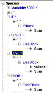
Note — Similar to IfCheck except that it allows the execution of multiple blocks when the "If" condition is TRUE.
IfBlockIfCheck
-
Function — BRANCHING
-
Status — ACTIVE
-
Input —
- Text: Not Used
- Value: The value of the expression (TRUE or FALSE)
-
Comment — Added V7.3
-
Input —
- Text: Not Used
- Value: The value of the expression (TRUE or FALSE)
This macro determines whether to call the IfCheck macro or the IfBlock macro depending on whether there is anything else on the block to be processed other than a "THEN" or a comment and depending on if this is an embedded IF (an IF statement within an IF statement). If there is something that is conditionally left to be processed and this is not an embedded IF statmenet, then call IfCheck. Otherwise, call both IfBlock and IfCheck.
The concept is you have one of the following 2 scenarios:
-
IF (condition) THEN GOTO ...
-
or
-
IF (condition) THEN
-
...
-
ELSE
-
...
-
ENDIF
IfBlockIfCheck2
-
Function — BRANCHING
-
Status — ACTIVE
-
Input —
- Text: Not Used
- Value: The value of the expression (TRUE or FALSE)
This macro determines if the IF on the block is a single line IF statement or a multi-line IF block. IF we determine this is a multi-line IF block, then we will call the macros IfBlock and IfCheck. Otherwise we will only call IfCheck. If there is nothing to be executed on this line (for example: GOTO or a setting of a variable), then this must be a multi-line IF block. Otherwise, this is a single block IF statement.
The concept is you have one of the following 2 scenarios: A single line IF statement, for example:
-
IF (condition) THEN GOTO ...
-
OR A multi-line IF Block, for example:
-
IF (condition) THEN
-
...
-
ELSE
-
...
-
ENDIF
IfCheck
-
Function — BRANCHING
-
Status — ACTIVE
-
Input —
- Text: Not Used
- Value: The value of the expression
Sets an internal condition indicating whether the corresponding "IF" statement was TRUE or FALSE. This variable is reset at the beginning of the next block. If the value is greater than -1 and less than 1, the condition is set to FALSE. Otherwise, the condition is set to TRUE.
This macro is used to process an "If" check of the form:
-
If (expression) GOTO 30
-
.
-
.
-
.
-
GOTO 40
-
N30
-
.
-
.
-
.
-
GOTO 40
-
N40
-
In the above example, the value of the expression will determine how the remainder of the block will be processed. If the macro IfCheckAllMacros was called with a value of 1, then the condition determines if anything else on the block will be executed. Otherwise, the condition will determine if variable assignments will be executed, and will determine if the following macros will be executed.
-
MACROS
IfCheckAllMacros
-
Function — BRANCHING
-
Status — ACTIVE
-
Input —
- Text: Not Used
- Value: 1 = Apply to all macros
Any other value = Apply to only restricted list (Default) If this macro is passed a value of 1, it causes the IfCheck macro to be applied to all macros called after the IfCheck on the current block. Typically, this macro would be called during the "Start of Processing" event.
See Also — ResetIfCheck, NumIfCheck, and HeidMPlusIfCheck Note — The IfCheck also applies to whether comments are passed on, and if variable assignments are executed. This is independent of IfCheckAllMacros.
IfCheckAllPartial
-
Function — BRANCHING
-
Status — ACTIVE
-
Input —
- Text: Not used
- Value: The value of the expression
-
Comment — Added in V9.2
-
Input —
- Text: Not used
- Value: The value of the expression
This macro is the same as IfCheck, except it applies to all Partial Blocks that follows. If the value is FALSE, processing will advance to the next line. This macro was created for the Laserdyne control. On this control, a line can contain multiple partial blocks. This macro also sets IfCheckAllMacros to TRUE.
For example:
-
IF (expression) call sub: set variable
-
In the above line, if the expression is true, it will then call the subroutine. When it finishes processing the subroutine, it will then set the variable. If the expression is false, it will immediately advance to the next line.
IfCheckZero
-
Function — BRANCHING
-
Status — ACTIVE
-
Input —
- Text: Not Used
- Value: The value of the expression
This macro is identical to IfCheck, except for how the condition is set. Sets an internal condition indicating whether the corresponding "IF" statement was TRUE or FALSE. This variable is reset at the beginning of the next block. If the value is zero the condition is set to FALSE. Otherwise, the condition is set to TRUE.
This macro is used to process an "If" check of the form:
-
If (expression) GOTO 30
-
.
-
.
-
N30
-
In the above example, the value of the expression will determine how the remainder of the block will be processed. If the macro IfCheckAllMacros was called with a value of 1, then the condition determines if anything else on the block will be executed. Otherwise, the condition will determine if variable assignments will be executed, and will determine if the following macros will be executed.
-
MACROS
IfSpecialParsing
-
Function — BRANCHING
-
Status — ACTIVE
-
Input —
- Text: Not Used
- Value: 0 = Use standard parsing (default)
-
0 = Use standard parsing (default)
- 1 = Treat: “IF variable …” as a check for the exsistance of the variable.
Normally, the expression “IF variable …” checks if the variable exist and the value is non_zero. If this macro is called with an value of 1, a check will only be made for the existence of the variable. This command is modal, and therefore would normally be called, if needed, during start of processing.
Note — This only applies when “variable” is the only thing in the IF expression. It does not apply in situations where the IF expression
IgnoreEqualWithAlpha
-
Function — MISCELLANEOUS
-
Status — ACTIVE
-
Input —
- Text: Not Used
- Value: 0: No, do not ignore the ‘=’ (default)
-
Comment — Added V9.6
-
Input —
- Text: Not Used
- Value:
- 0: No, do not ignore the ‘=’ (default)
- 1: Yes, ignore the ‘=’
If you define a Word to have an Alpha or Alpha-Numeric argument, you traditionally could not have a ‘=’ between the Word and the Value.
For example, assume “NAME” is a Word with an Alpha-Numeric argument, and “DAVE” is just a character string, and you assign it as follows:
-
NAME = DAVE
-
In this case, NAME would have “” as its value. NOTE: The Value ends when we read the ‘=’ because this is not an alpha numeric character.
-
If you call this macro with OV=1, the ‘=’ will be ignored, and the variable NAME would be set to “DAVE”.
IgnoreMacro
-
Function — MISCELLANEOUS
-
Status — ACTIVE
-
Input —
- Text: Not Used
- Value: Used in Reports
Ignores the word/value that called it (causes no action). During the creation of a report, the macro will create an unsupported word/value entry.
IgnoreTableRotMatrix
-
Function — ROTATION PLANE
-
Status — ACTIVE
-
Input —
- Text: Not Used
- Value: 0 = Do not ignore the Rider rotation in the calculation of the Driven Point Zero coordinates (Default)
-
Comment — Added V7.3.1
-
Input —
- Text: Not Used
- Value:
- 0 = Do not ignore the Rider rotation in the calculation of the Driven Point Zero coordinates (Default)
- 1 = Ignore the Rider rotation in the calculation of the Driven Point Zero coordinates
This macro is used to resolve the Working Plane matrix when the Rotary table (Rider) position is relevant to the calculation of dynamic work offsets but it is ignored in orientation of Driven Point Zero coordinates. This condition is typical for Cycle 19 command in a Heidehein control.
To ignore the Rider rotation in the calculation of the Driven Point Zero coordinates, set Override Value = 1. The default Override Value = 0.
In Siemens 840D ORISOL command this macro can be used to solve singularity problem when tool is vertical to table. This macro ignores table rotation when calculating spindle orientation for tool.
Ijk2AbcIgnoreLimits
-
Function — MISCELLANEOUS
-
Status — ACTIVE
-
Input —
- Text: Not Used
- Value: 1 = Ignore Travel Limits
-
Comment — Added V7.1
-
Input —
- Text: Not Used
- Value:
- 1 = Ignore Travel Limits
- Any other value = Do Not Ignore Travel Limits (Default)
This macro turns off travel limit checking when converting IJK value to ABC values and outputs the converted solution even if the motion will create an error for exceeding the travel limits. It will still print an error to show that the machine has exceeded its travel limits and halt the simulation.
Ijk2AbcInput
-
Function — MISCELLANEOUS
-
Status — ACTIVE
-
Input —
- Text: IJK, ABC or CBA
- Value: Not Used
-
Comment — Added V7.1.6
-
Input —
- Text: IJK, ABC or CBA
- Value: Not Used
This specifies the type of input that will be used to define the orientation for the Ijk2Abc conversion. Initially, this was implemented for Ijk2AbcType = 99. To input the IJK Tool Axis Vector, call IVector, JVector, KVector, or IJKVector. To input the Virtual Angles, call IjkAAxisMotion, IjkBAxisMotion, or IjkCAxisMotion. The Type 99 conversion also supports orienting the tool. If the Input type is IJK, then IVector2, JVector2, KVector2, or IJKVector2 macros should be called to define the X Axis Vector.
Ijk2AbcOffsetAdjust
-
Function — MACRO_WORK_OFFSETS
-
Status — ACTIVE
-
Input —
- Text: Not Used
- Value: 0 = no adjustments are made to calculated rotary axis angles (Default)
-
Comment — Added V7.0.4
-
Input —
- Text: Not Used
- Value:
- 0 = no adjustments are made to calculated rotary axis angles (Default)
- 1 = calculated angles are adjusted by the current offset values
This macro is used to modify calculated rotary axis values when an input tool axis vector (IJK components) is converted to a rotary axis ABC position. If the Override Value is set to 1, then the calculated angles are adjusted by the current offset values. This behavior is specific for 840D control. The default is Override Value set to 0 where no adjustments are made to calculated rotary axis angles.
Ijk2AbcPartRot
-
Function — MISCELLANEOUS
-
Status — ACTIVE
-
Input —
- Text: Not Used
- Value: 1 = Specifies the Tools orientation relative to the Part.
-
Comment — Added V7.1.6
-
Input —
- Text: Not Used
- Value:
- 0 = Specifies the Tools orientation relative to the Base (Default)
- 1 = Specifies the Tools orientation relative to the Part.
This attribute is specific to the Ijk2Abc conversion Type =99.
Ijk2AbcSolution
-
Function — MISCELLANEOUS
-
Status — ACTIVE
-
Input —
- Text: Not Used
- Value: 0 = do not apply WorkingPlane2Abc rules (Default)
-
Comment — Added V7.1.6
-
Input —
- Text: Not Used
- Value:
- 0 = do not apply WorkingPlane2Abc rules (Default)
- 1 = apply WorkingPlane2Abc rules
There are several macros used to set rules when selecting one of the two possible solutions for rotary position. Some of them are specific to WorkingPlane2Abc logic and others are specific to Ijk2Abc conversion. This macro enables applying the WorkingPlane2Abc rules when solving regular Ijk2Abc conversion.
An Override Value of 1 will use the WorkingPlane2Abc rules when solving regular Ijk2Abc conversion. An Override Value of 0, the default, will not use the WorkingPlane2Abc rules when solving regular Ijk2Abc conversion.
Ijk2AbcSpindleOrient
-
Function — MISCELLANEOUS
-
Status — ACTIVE
-
Input —
- Text: Not Used
- Value: 0 = use the Tool Z axis for the IJK to ABC conversion (default)
-
Comment — Added V7.3.2
-
Input —
- Text: Not Used
- Value:
- 0 = use the Tool Z axis for the IJK to ABC conversion (default)
- 1 = use the Spindle component Z axis for the IJK to ABC conversion
This macro is used to select which Z axis to use when solving the IJK to ABC conversion. By default Vericut always uses the Tool component Z axis. In some cases the Tool component is defined differently and the tool spinning axis is not its Z axis. In this case you can use the Spindle component Z axis for the conversion.
Use Override Value =1 to use the Spindle component Z axis instead of Tool Z axis. The default is Override Value = 0, to use the Tool component Z axis. For now this macro affects only the IJK to ABC calculation.
Ijk2AbcToolOrient
-
Function — MISCELLANEOUS
-
Status — ACTIVE
-
Input —
- Text: Not Used
- Value: 1 = Orient the Tool if possible (default)
-
Comment — Added V7.1.6
-
Input —
- Text: Not Used
- Value:
- 0 = Do not orient the Tool
- 1 = Orient the Tool if possible (default)
This attribute is specific to the Ijk2Abc conversion Type =99. Typically, only the Tool Axis Vector is given, and the Ijk2Abc converstion Type = 99 can be used to calculate the 2 real angles to achieve the specified orientation.
If an XAxisVector is also specified, or if Virtual angles are specified, and if the Tool has a C orientation axis, then the Ijk2Abc conversion Type = 99, can also be used to calculate the 3 real angles to achieve the specified orientation. Given the proper input, and the necessary machine kinematics, this attribute turns this feature “on” and “off”.
Ijk2AbcType
-
Function — ROTATION PLANE
-
Status — ACTIVE
-
Input —
- Text: Not Used
- Value: Conversion Type: 1-42, 99 (default)
Rather than specifying the rotary angle directly (A30 B45), the NC Program might specify the orientation of the Tool (typically relative to part). This is passed as an IJK vector. This vector corresponds to the orientation of the Z axis. A second IJK vector, specifying the X Axis orientation might or might not be given. This macro specifies the algorithm that should be used to convert the IJK values to ABC values.
There are two classes of conversion routines, "Generic" and "Specific".
-
Generic: These are now obsolete. The Conversion Type should be set to 99, and you should set Ijk2AngleLogic OV=1. See also: Ijk2Angles macros to set various parameters.
-
Specific: Each Specific Conversion Type is for a specific, special machine. For Special machines, for example the Tricept, also set Ijk2AnglesLogic OV=0. With Ijk2AnglesLogic set to 0, you will use the Ijk2Abc macros to set various parameters.
Valid Values (conversion types):
- 1 = Specific: Forest Line 5ax mill with A/B head rotation and ATEK control.
In this case, the macro also rotates the work and shift offsets based on the rotation that is applied to the stock. An assumption is made that the entire amount of the dynamic and work offsets should be rotated by the amount the part is rotated. This logic will not work when the machine is not built about zero, and only part of the work offset is to be rotated.
-
Note —
-
Rotary control settings should be set to "Absolute" with the direction set to "Shortest Distance".
-
This option uses a rotation plane to adjust the coordinate system for any rotation of the B axis (part side rotary). This option cannot be used with RPCP or Rotation Planes.
-
-
2 = Semi Generic A-B
For example, a Droop & Rein 5ax mill with A/B table rotation and Makro 80 control. Similar to case 1 above, except both A/B rotaries are on the "tool side" of the machine. This means that a rotation plane is not used to adjust for part side rotary, and therefore this option does not have the restriction on RPCP or Rotation Planes.
- 3 = Specific: 5-axis tripod type mill with A/B head rotation and Sinumerik 840D control.
A highly customized machine where the spindle/tool assembly rotates, it moves off center relative to the cylinder which surrounds it. To simulate this, "virtual" U and V axes were included in the machine definition. When offsets are applied to U and V, counter offsets are applied to X and Y. This option was designed to be driven via Z1, A1, Z2, A2, Z3 and A3 NC codes, the tool is actually driven with A, B, C.
See Also — TripodArmLength and TripodRodLength.
-
4 = Generic B-C with rotaries set to linear. Obsolete - use Ijk2AnglesLogic (OV=1).
-
5 = Generic A-C with a 50 degree nutator. Obsolete - use Ijk2AnglesLogic (OV=1).
-
6 = Generic A-C with a 50.02 degree nutator. Obsolete - use Ijk2AnglesLogic (OV=1).
-
7 = Generic A-C. Obsolete - use Ijk2AnglesLogic (OV=1).
-
8 = Generic B-C, also supports any angle nutator. Obsolete - use Ijk2AnglesLogic (OV=1).
-
9 = Generic B-C, also supports any angle nutator. Obsolete - use Ijk2AnglesLogic (OV=1).
-
10 = Generic A-C, also supports any angle nutator. Obsolete - use Ijk2AnglesLogic (OV=1).
-
11 = Generic B-A. Obsolete - use Ijk2AnglesLogic (OV=1).
-
12 = Generic A-B. Obsolete - use Ijk2AnglesLogic (OV=1).
-
13 = Generic A-C with A,B,C input. Obsolete - use Ijk2AnglesLogic (OV=1).
-
14 = Generic C-B, also supports any angle nutator. Obsolete - use Ijk2AnglesLogic (OV=1).
-
15 = Specific: Old ElectroImpact Tape laying machine
-
16 = Specific: Old Test Tape laying machine
-
17 = Specific: 5-axis tripod type mill with a B/A head rotation
-
18 = Specific: Tricept machine.
-
19 = Specific: ElectroImpact Tape laying machine
-
20 = Specific: Tricept machine with no travel limit checks.
-
21 = Generic: A. Obsolete - use Ijk2AnglesLogic (OV=1).
-
22 = Generic: B. Obsolete - use Ijk2AnglesLogic (OV=1).
-
23 = Generic: C. Obsolete - use Ijk2AnglesLogic (OV=1).
-
24 = Specific: 6-axis tripod type mill with a C/B/A head rotation and a right-angle head.
-
25 = Generic: B-A, also support nutator at any angle. Obsolete - use Ijk2AnglesLogic (OV=1).
-
26 = Generic: B-C machine with two nutator angles. Obsolete - use Ijk2AnglesLogic (OV=1).
-
27 = Specific: Cincinnati Viper 1200 tape machine
-
28 = Specific: Tricept – Similar to option 18 except Component A24 rotated 90 degrees
-
29 = Specific: Tricept – Similar to option 20 except Component A24 rotated 90 degrees
-
30 = Specific: Tape with a generic VCP posted output. This machine contains 4 channels, and a Rotisserie.
-
31 = Specific: For robots with 5 or 6 rotary axis. Supports KUKA, Kawasaki, Fanuc, ABB.
Current logic automatically resolves the inverse kinematics of most robots built by KUKA, Kawasaki, Fanuc and ABB. This is the only indicator that the machine kinematics is a robot.
-
32 = Specific: Supports a Brown fastener machine where the Y-axis is not supported directly and the Z-axis is virtual.
-
33 = Specific: Supports tripod type kinematic heads using Link components.
-
34 = Specific: Simplified tricept machine
-
35 = Specific: Supports Brotje fastener kinematic.
-
36 = Specific: 5-pod machine
-
37 = Specific: Accudyne BAC machine
-
38 = Specific: Exechon Tricept machine
-
39 = Specific: Tricept machine. Updated version of 24, with embedded ORIRPY subroutine logic.
When a right-angle head is loaded on a Tricept machine, we have traditionally called a ORIRPY subroutine which converts the A2=. B2=, C2= input into C2,B,A angles. We then used these angles to drive the tricept machine. With option 39, you no longer need the ORIRPY subroutine. NOTE: A2=, B2=, C2= needs to call IjkAAxisMotion, IjkBAxisMotion, and IjkCAxisMotion.
-
40 = Specific: ElectroImpact Tape laying machine – simplified version of Type=19, part rotates about Y using B2
-
41 = Specific: Accudyne CAC machine
-
42 = Specific: Tricept – part side (moving platform, stationary tool)
-
99 = Universal (Default)
Note — Handles all standard machines with 1,2,or 3 rotaries. With this Type, all Generic conversion Types become obsolete. With this type, Ijk2AnglesLogic should be set to new (OV = 1), and you should use the Ijk2Angles macros rather than the Ijk2AbcType macros.
Ijk2AbcType19ApplyWORotation
-
Function — ROTATION PLANE
-
Status — ACTIVE
-
Input —
- Text: Not Used
- Value: 0=Do not apply (default), 1=Apply
This macro determines if the Work Offset Rotations should be applied to the Ijk2Abc Type=19 conversion logic. The default is no.
Ijk2Angles
-
Function — ROTATION PLANE
-
Status — ACTIVE
-
Input —
- Text: axis1var axis2var angle1var angle2var angle1var2 angle2var2 rcvar
- Value: Not used
-
Comment — Added in V9.0
-
Input —
- Text: axis1var axis2var angle1var angle2var angle1var2 angle2var2 rcvar
- Value: Not used
This macro calculates the rotary axis angles needed to orient the tool (relative to the part) to a previously specified tool-axis direction. It performs the calculation only — no machine motion takes place and no offsets are updated. The results are written into the variables you name: the two rotary axes involved, both candidate solutions (first and second angle of each), and a return code giving the number of solutions found.
The tool-axis orientation that gets converted can be supplied in several ways. The most common is an IJK vector (set with IVector, JVector, KVector), but it can also be given as ABC or CBA angle triplets, or taken from the machine's real rotary positions. The active input method is selected with Ijk2AnglesInput and defaults to IJK.
The first solution is the preferred one, chosen according to the rules set with Ijk2AnglesPickSolution. The return code reports how many valid solutions exist (0, 1, or 2); if the conversion fails, the return-code variable is set to 0.
Note — In practice this macro is seldom called directly. The IJK-to-angles conversion it performs is normally invoked automatically, as part of processing motion driven by a tool-axis orientation (and by working planes and Siemens ORIVECT moves). Call Ijk2Angles only when you specifically need the angles calculated without any motion. The rules configured by the rest of this macro family apply to the automatic conversions as well.
Examples
Examples 1–3 show the on-demand call (uncommon). Example 4 shows the far more typical case, where the conversion happens automatically as motion is processed and Ijk2Angles is never called explicitly.
Example 1 — capture both solutions and the count. With an IJK tool-axis vector already active, request the conversion into seven result variables:
After the call, for a typical A/C machine the variables might hold:
AXIS1 = "A"      AXIS2 = "C"
ANG1A = -30.0    ANG2A = 45.0      (preferred solution)
ANG1B =  30.0    ANG2B = 225.0     (alternate solution)
NSOL  =  2
Example 2 — react to the number of solutions. NSOL is the safe way to know whether the orientation is reachable:
NSOL = 0— the tool-axis direction cannot be reached with the available rotaries.NSOL = 1— exactly one solution; use the preferred-solution variables.NSOL = 2— two solutions; the preferred one is chosen by Ijk2AnglesPickSolution, the other is available in the second-solution variables.
Example 3 — preferred solution only. Omit the optional arguments when the alternate solution and count are not needed:
Only the first (preferred) solution is captured; the second-solution variables and the return code are left unset.
Example 4 — the conversion triggered automatically by vector-programmed motion (typical case). Many controls drive the tool by orientation rather than by commanding rotary angles. The conversion then runs by itself as the motion block is processed — Ijk2Angles is not called. For example, a vector-programmed linear move supplies a tool-axis vector (T) and a second orientation vector (N):
As the block is processed, TX/TY/TZ set the tool-axis vector via IVector / JVector / KVector, and NX/NY/NZ set the second orientation vector via IJKVector2 / JVector2 / KVector2. VERICUT then converts these into rotary angles automatically.
Here the tool axis points straight up (TZ = 1). On an A/C machine this is the vertical case — the C axis is aligned with the tool axis, so the tool-axis vector alone leaves C undetermined (both candidate solutions come out A = 0, C = 0). The second vector resolves it: with the vertical rule set to ORIENT (see Ijk2AnglesVerticalRule), NY = 1 is used to orient C, giving the final solution A = 0, C = 90. No call to Ijk2Angles was needed — the rules configured by this macro family governed the automatic result.
See also
- Ijk2Angles2 — same calculation, results go to pre-registered variables
- Ijk2AnglesSaveSolutions — register the variables used by
Ijk2Angles2 - Ijk2AnglesInput — choose the input method (IJK / ABC / CBA / REAL_ANGLES)
- Ijk2AnglesPickSolution — rules that decide which solution is "first"
- Ijk2AnglesLogic — overall enable/behavior of the IJK-to-angles conversion
- IVector, JVector, KVector — set the tool-axis vector that this macro converts
Ijk2Angles2
-
Function — ROTATION PLANE
-
Status — ACTIVE
-
Input —
- Text: Not used
- Value: Not used
-
Comment — Added in V9.0
-
Input —
- Text: Not used
- Value: Not used
This macro calculates the angles necessary to align the Z axis of the tool, relative to the part, to the input vector that was previously set. This is a modified version of the Ijk2Angles macro. No arguments are passed. This macro should only be used if the macro Ijk2AnglesSaveSolutions has been called, and you don’t need any other variables set.
Note — The purpose of Ijk2AnglesSaveSolutions, is to automatically set variables with the results any time an IJK to Angles calculation is made. See Ijk2Angles for more details.
Ijk2AnglesAddOffset
-
Function — ROTATION PLANE
-
Status — ACTIVE
-
Input —
- Text: Not Used
- Value: 0 = Do not add offset, 1 = add offset(default)
-
Comment — Added in V8.0
-
Input —
- Text: Not Used
- Value: 0 = Do not add offset, 1 = add offset(default)
This macro determines how the IJK is to be interpreted if there is an offset on either of the rotary components. Does it represent the actual tool to stock orientation, or the orientation when the rotary offsets are zero. Another way to say this is: after calculating the resulting angle, should it be added to the offset for that rotary. For example: “A” offset is 20. IJK produces a solution of 35. Should the machine be driven to 35 or 55? A value of 1 pass to this macro would cause the 20 offset to be added to the 35 to then drive the machine to 55.
Ijk2AnglesApplyMirroring
-
Function — ROTATION PLANE
-
Status — ACTIVE
-
Input —
- Text: Not used
- Value: 1 = yes, 0 = no (default)
-
Comment — Added in V8.2
-
Input —
- Text: Not used
- Value: 1 = yes, 0 = no (default)
This macro determines if Mirroring should be applied to the IJK vector before converting it to angles. If yes, it will use the rotation plane specified with RotationPlaneMirrorIndex to determine which mirroring has been turned on.
Note — This Rotation Plane must contain only Mirroring. This macro is associated with all other macros beginning with Ijk2Angles.
Ijk2AnglesApplyWORotation
-
Function — ROTATION PLANE
-
Status — ACTIVE
-
Input —
- Text: Not Used
- Value: 1=YES, 0=NO (default).
-
Comment — Added V9.2
-
Input —
- Text: Not Used
- Value: 1=YES, 0=NO (default).
This macro specifies whether to apply Work Offset Rotations to IJK values when converting IJk2Angles.
Ijk2AnglesDefaultFromTo
-
Function — ROTATION PLANE
-
Status — ACTIVE
-
Input —
- Text: Not used
- Value: 0 (default) = use Tool and Stock, 1 = Calculate and Adjust the From/To based on the machine kinematics
-
Comment — Added in V8.2
-
Input —
- Text: Not used
- Value: 0 (default) = use Tool and Stock, 1 = Calculate and Adjust the From/To based on the machine kinematics
By default, the Ijk2Angles logic is interpreting the IJK as the orientation of the Z axis of the Tool (FROM) relative to the stock (TO). Calling this macro with a value of 0 restores this default setting. Calling this macro with a value of 1 causes the following during the IJK to Angles conversion 1. If both rotaries being used in the IJK to Angles calculation are on the Tool side, set the TO component to be the base. This results in the orientation of the part NOT effecting the calculations. 2. If both rotaries being used in the IJK to Angles calculation are on the Part side, set the FROM component to be the base. This results in the orientation of the tool NOT effecting the calculations.
-
If the FROM component is a TOOL component, change it to be the parent of the tool. This might be desirable for 2 reasons:
-
- Sometimes you are working with a right angle head, and the IJK should not take this into account.
-
- We want the FROM component to be the spindle, and hopefully the spindle is the parent of the Tool.
-
- If the FROM component is a SPINDLE component, or a ROTARY component acting as a spindle component, then ignore the spindle orientation in all Ijk2Angle and Working Plane calculations.
-
The intent of this macro is establish the FROM/TO components in a manner where they do not need to be specified directly, and to avoid needing to create a dummy component above the spindle. If any of the above items are not desirable, then this macro should not be called with a value of 1.
Note — This setting is modal.
Ijk2AnglesFromComponent
-
Function — ROTATION PLANE
-
Status — ACTIVE
-
Input —
- Text: Name of component
- Value: Not Used
-
Comment — Added in V8.0
-
Input —
- Text: Name of component
- Value: Not Used
IJK typically specifies the orientation of the Z axis of the active tool relative to the stock. It is highly recommended that you define the machine in this manner. This macro, however, give you the opportunity to define any component as your “FROM” component.
Ijk2AnglesInput
-
Function — ROTATION PLANE
-
Status — ACTIVE
-
Input —
- Text: IJK (default) | ABC | CBA | REAL_ANGLES
- Value: Not Used
-
Comment — Added in V8.0
-
Input —
- Text: IJK (default) | ABC | CBA | REAL_ANGLES
- Value: Not Used
This macro defines how the tool-axis orientation is supplied to the IJK to Angles conversion. The default is IJK.
- IJK — A tool-axis vector set with IVector, JVector, KVector. An optional second (orientation) vector, set with IVector2/JVector2/KVector2 (or the generic IJKVector2), can fully constrain the orientation rather than just the tool axis.
- ABC — Three angles set with the Ijk[A/B/C]AxisMotion macros, combined in ABC order (A, then B, then C).
- CBA — The same three angles, combined in CBA order (C, then B, then A).
- REAL_ANGLES — The orientation implied by the machine’s actual current rotary positions.
Ijk2AnglesLinearAdjustOption
-
Function — ROTATION PLANE
-
Status — ACTIVE
-
Input —
- Text: Not Used
- Value: 1 = BEFORE (default), 2 = AFTER
First, what is Linear Adjust? For a linear rotary table (not an Absolute table), if we are currently at 360, and told to go to 90 degrees, we could either go to 90 or 450. Linear Adjust refers to picking the closest angle that obeys travel limits.
This macro sets an option on when we apply “Linear Adjust” within the Ijk2Angles logic. The following is the typical order of operation when we execute IJK to Angles (value = 1):
-
1. Convert IJK to Angles
-
2. Apply Linear Adjust
-
3. Pick the Best solution that obeys Travel limits
-
When this macro is called with a value of 2 (AFTER), the Linear Adjust will be applied AFTER picking the best solution that obeys Travel Limits.
-
It is expected that this macro will seldom need to be called.
Ijk2AnglesLinearIgnoreLimits
-
Function — ROTATION PLANE
-
Status — ACTIVE
-
Input —
- Text: Not Used
- Value: 0 = Do not ignore limits (default), 1 = ignore limits
-
Comment — Added in V8.0
-
Input —
- Text: Not Used
- Value: 0 = Do not ignore limits (default), 1 = ignore limits
For a linear component, if IJK results in an angle of 30, we adjust this angle to be the closest angle to the local position. For example: If we are currently at 340, we set the angle to 390. The question is: if 390 violates travel limits, should we set the angle to 30. A value of 0 would say to check travel limits, and then set the angle to 30. A value of 1 would ignore travel limits, and set the angle to the nearest angle – 390.
Ijk2AnglesLogic
-
Function — ROTATION PLANE
-
Status — ACTIVE
-
Input —
- Text: Not Used
- Value: 0 = Use old logic (default), 1 = Use new logic
-
Comment — Added in V8.0
-
Input —
- Text: Not Used
- Value: 0 = Use old logic (default), 1 = Use new logic
This macro determines which IJK2ABC logic to use. <!-- See Notes about IJK to ABC section in Notes About Special Topics for an overview of the new IJK2ABC logic.
Ijk2AnglesPartZeroAdjust
-
Function — ROTATION PLANE
-
Status — ACTIVE
-
Input —
- Text: Not Used
- Value: 0 = Do not adjust (default), 1 = Adjust Working Plane calculations only, 2 = Adjust Working Plane calculations and IJK-to-angles conversions
-
Comment — Added in V9.1
-
Input —
- Text: Not Used
- Value:
- 0 — Do not adjust (default)
- 1 — Adjust Working Plane calculations only
- 2 — Adjust Working Plane calculations and IJK-to-angles conversions
Determines whether the input IJK is adjusted by the orientation of the part when the machine is driven to its local zero, before the IJK is converted into angles. When enabled, any offsets on the part-side rotary axes will affect the resulting IJK.
See also — Ijk2AnglesAddOffset Note — This is most significant when there are offsets on the part-side rotaries.
Ijk2AnglesPickSolution
-
Function — ROTATION PLANE
-
Status — ACTIVE
-
Input —
- Text: A series of space separated value, specifying the rules
- Value: Not used
-
Comment — Added in V8.0
-
Input —
- Text: A series of space separated value, specifying the rules
1 = Travel Limits
2 = Shortest total travel for both rotaries
3 = Shortest travel for first rotary
4 = Shortest travel for second rotary
5 = Negative value of first rotary when converted to -180 to 180
6 = Negative value of second rotary when converted to -180 to 180
7 = Positive value of first rotary when converted to -180 to 180
8 = Positive value of second rotary when converted to -180 to 180
9 = Larger value of first rotary when converted to 0 to360
10 = Larger value of second rotary when converted to 0 to360
11 = Smaller value of first rotary when converted to 0 to360
12 = Smaller value of second rotary when converted to 0 to360
13 = Shortest total distance from zero for both rotaries
14 = Shortest distance from zero for first rotary
15 = Shortest distance from zero for second rotary
16 = Input Angles - both angles must match
-
Value: Not used
When converting IJK to 2 rotary angles, there are typically two solutions. This macro is used to specify which rules we will use to pick the best solution. You can pick up to 5 rules. The rules will be applied in order. If a rule does not define a best solution, we will continue with the next rule.
Ijk2AnglesPickSolution180Option
-
Function — ROTATION PLANE
-
Status — ACTIVE
-
Input —
- Text: Not used
- Value: 180 (default) or -180
-
Comment — Added in V9.1
-
Input —
- Text: Not used
- Value: 180 (default) or -180
When converting IJK into angles, there are typically 2 solutions. The macro Ijk2AnglesPickSolution is used to determine which solution to pick. For some of the Pick Solutions, we convert the angle to between -180 and 180. IF one of the solution angles is 180, this could be 180 or -180. By default, we say the angle is 180. This macro allows you to define whether this angle should be 180 or -180.
Ijk2AnglesPickSolutionZeroOption
-
Function — ROTATION PLANE
-
Status — ACTIVE
-
Input —
- Text: Not used
- Value: 0 (default) = zero is neither positive or negative
-
Comment — Added in V9.1
-
Input —
- Text: Not used
- Value:
- 0 (default) = zero is neither positive or negative
- 1 = in special circumstances zero can be consider positive or negative
When converting IJK into angles, there are typically 2 solutions. The macro Ijk2AnglesPickSolution is used to determine which solution to pick.
For some of the Pick Solutions, we are choosing the positive or negative angle. In these cases, this macro determines how zero should be interpreted.
| Pick rule | Angle | 180 Option | Treated as |
|---|---|---|---|
| Positive | 0 | -180 | neither (0) |
| Positive | 0 | 180 | 180 |
| Negative | 0 | -180 | -180 |
| Negative | 0 | 180 | neither (0) |
Ijk2AnglesRotaries
-
Function — ROTATION PLANE
-
Status — ACTIVE
-
Input —
- Text: Name of the 2 rotary components to used – space separated
- Value: Not Used
-
Comment — Added in V8.0
-
Input —
- Text: Name of the 2 rotary components to used – space separated
- Value: Not Used
This macro is used to specify the rotaries that will be used with the IJK to angles logic. The “name” can be either the actual name of the component, or the register name (A,B,C,…) * If only 1 rotary will be used, the second rotary should be marked as “NONE”. * The third rotary is optional, and if present, must represent the spindle orient rotary. This macro will first verify that the specified components exists on the current subsystem, and that they are Rotary components. It will then look to see which of the first 2 components is the first component from the active Tool to the active Stock. If neither rotary is in this path, an error will be returned.
Note — If there are multiple stocks, make sure the correct one is marked as the active stock. For simple machines, you do not need to call this macro. We will determine the rotaries to use based on the machine kinematics and the following rules:
-
- We will look for the rotaries starting at the active Tool component going to the “TO” component (typically active Stock).
-
- If the first rotary is on the Tool side and rotates about the tool axis, this will be considered the third rotary.
-
- Locked components (see RotaryAxisLock) will not be used.
Ijk2AnglesRotariesVarInput
-
Function — ROTATION PLANE
-
Status — ACTIVE
-
Input —
- Text: Name of two variables, each specifying a rotary component or a register – space separated
- Value: Not used
-
Comment — Added in V8.2
-
Input —
- Text: Name of two variables, each specifying a rotary component or a register – space separated
- Value: Not used
This macro is used to specify the rotaries that will be used with the IJK to angles logic. The default is the first and second rotaries as found going from the Tool to the Stock. We will first try to match the specified name with a component. If no component exist, it will look for component on the current subsystem with the matching register name (A,B,C…) The rotaries can be specified in either order. The macro will determine which is first, and which is second.
Note — When calculating the default, if the first rotary rotates about the tool axis, this rotary will be ignored by default
Ijk2AnglesSaveSolutions
-
Function — ROTATION PLANE
-
Status — ACTIVE
-
Input —
- Text: axis1var axis2var angle1var angle2var angle1var2 angle2var2 rcvar
- Value: Not Used
-
Comment — Added in V9.2
-
Input —
- Text: axis1var axis2var angle1var angle2var angle1var2 angle2var2 rcvar
- Value: Not Used
If this macro is called, then anytime the ijk to angles logic is executed, then these variables will be set to their corresponding values.
Ijk2AnglesToComponent
-
Function — ROTATION PLANE
-
Status — ACTIVE
-
Input —
- Text: Name of component
- Value: Not Used
-
Comment — Added in V8.0
-
Input —
- Text: Name of component
- Value: Not Used
IJK typically specifies the orientation of the Z axis of the active tool relative to the stock. It is highly recommended that you define the machine in this manner. This macro, however, give you the opportunity to define any component as your “TO” component.
Ijk2AnglesTolerance
-
Function — ROTATION PLANE
-
Status — ACTIVE
-
Input —
- Text: Not used
- Value: Tolerance category
-
Comment — Added V9.5.x
-
Input —
- Text: Not used
- Value: Tolerance category
- 1 = Tight (default, existing)
- 2 = Medium
- 3 = Course
This macro is used to set a tolerance category to be used in the Ijk2Angles calculations. In general, this is used to determine if an IJK vector value should be considered 0 or 1. For example: Should the IJK vector: (0.0000001, 0.0000001, 0.99999999) be considered (0,0,1).
Typically, this macro does not need to be called. It should only be called if it is determined that tolerances are causing a problem with the IJK to Angles calculation. In the original case where this macro was needed, there was a BC nutator table, and the C axis on the machine was rotate 26.1182960215 degrees.
Ijk2AnglesVerticalRule
-
Function — ROTATION PLANE
-
Status — ACTIVE
-
Input —
- Text: 0 = Stay in the original position
- Value: Specified angle, used when the Text value is 1 or 4.
-
Comment — Added in V8.0
-
Input —
- Text: 0 = Stay in the original position
- Value: Specified angle, used when the Text value is 1 or 4.
The Vertical Rule is associated when the rotation of the first rotary causes the second rotary to rotate about the new tool axis. In this situation, the second rotary could be rotated to any angle without effecting the specified IJK orientation. This macro defines what to do with the second rotary in this case. Typically, Ijk2Angles rotates 2 rotaries based on the IJK input. If the X Axis vector is specified, and there is a third rotary (that rotates about the tools Z axis), then the Ijk2Angles logic will use this third rotary to orient the Tool’s X axis. If we are in the vertical rule case, we only orient the third rotary for options 3 and 4.
Ijk2AnglesVerticalRuleZeroTol
-
Function — ROTATION PLANE
-
Status — ACTIVE
-
Input —
- Text: Not used
- Value: 0 = use a small tolerance (default), 1 = do not use a tolerance (zero tolerance)
-
Comment — Added in V8.2
-
Input —
- Text: Not used
- Value: 0 = use a small tolerance (default), 1 = do not use a tolerance (zero tolerance)
This macro specifies whether to use a tolerance when determining if the tool is vertical to the second rotary (second rotary rotates about the tool axis). This is used in the IJK to Angles computation. If it is determined to be vertical, the Vertical Rule is then applied (see Ijk2AnglesVerticalRule).
IjkAAxisMotion
-
Function — ROTATION PLANE
-
Status — ACTIVE
-
Input —
- Text: Not Used
- Value: Angle value
-
Comment — s: Added V8.0
-
Input —
- Text: Not Used
- Value: Angle value
This macro (along with IjkBAxisMotion and IjkCAxisMotion) sets generic angles that are used to create IJK and PQR vectors that are used with the IJK to ABC conversion logic. For the general case, in order to make use of these angles, you must call macro Ijk2AbcInput to define the order in which the angles are to be multiplied.
The general concept is then:
- Generic A,B,C angles are specified, they are multiplied in a specific order, and an IJK vector is retrieved from the corresponding resulting matrix. This IJK vector is then used by the IJK to ABC conversion logic.
Note — Macro Ijk2AbcType types 6, 13, and 27 use the angles directly, and the order in which to multiply the angles is fixed.
IjkBAxisMotion
-
Function — ROTATION PLANE
-
Status — ACTIVE
-
Input —
- Text: Not Used
- Value: Angle value
-
Comment — s: Added V8.0
-
Input —
- Text: Not Used
- Value: Angle value
This macro (along with IjkAAxisMotion and ) sets generic angles that are used to create IJK and PQR vectors that are used with the IJK to ABC conversion logic. For the general case, in order to make use of these angles, you must call macro Ijk2AbcInput to define the order in which the angles are to be multiplied.
The general concept is then:
- Generic A,B,C angles are specified, they are multiplied in a specific order, and an IJK vector is retrieved from the corresponding resulting matrix. This IJK vector is then used by the IJK to ABC conversion logic.
Note — Macro Ijk2AbcType types 6, 13, and 27 use the angles directly, and the order in which to multiply the angles is fixed.
IjkCAxisMotion
-
Function — ROTATION PLANE
-
Status — ACTIVE
-
Input —
- Text: Not Used
- Value: Angle value
-
Comment — s: Added V8.0
-
Input —
- Text: Not Used
- Value: Angle value
This macro (along with and ) sets generic angles that are used to create IJK and PQR vectors that are used with the IJK to ABC conversion logic. For the general case, in order to make use of these angles, you must call macro Ijk2AbcInput to define the order in which the angles are to be multiplied.
The general concept is then:
- Generic A, B, C angles are specified, they are multiplied in a specific order, and an IJK vector is retrieved from the corresponding resulting matrix. This IJK vector is then used by the IJK to ABC conversion logic.
Note — Macro Ijk2AbcType types 6, 13, and 27 use the angles directly, and the order in which to multiply the angles is fixed.
IJKVector
-
Function — ROTATION PLANE
-
Status — ACTIVE
-
Input —
- Text: Not Used
- Value: I, J, or K value of the vector
-
Comment — Added V6.1
-
Input —
- Text: Not Used
- Value: I, J, or K value of the vector
This macro is used to specify the IJK vector of the tool. It will set the I value on the first call on the block, the J value on the second call on a block, and the K value on the third call on a block. See also: IVector, JVector, KVector.
IJKVector2
-
Function — ROTATION PLANE
-
Status — ACTIVE
-
Input —
- Text: Not Used
- Value: I, J, or K value of the vector
-
Comment — Added V6.1
-
Input —
- Text: Not Used
- Value: I, J, or K value of the vector
This macro is used to specify the motion vector. It will set the I value on the first call on the block, the J value on the second call on a block, and the K value on the third call on a block.
IJKVectorModalOnOff
-
Function — MOTION
-
Status — ACTIVE
-
Input —
- Text: Not Used
- Value: 1 = modal (default), 0 = non-modal
If IJK values are specified in one line but not in the next, two things could happen. Either the values from the previous line could be kept, or the non-specified values could be reset to 0. This macro allows you to choose between these two options. If one wants the values of IJK to be retained when not specified, a value of 1 can be entered. Otherwise, if one wants the values to be set to 0 if not specified, a value of 0 can be entered. By default, the IJK values are retained when not specified.
InActivateAxes
-
Function — ACTIVATION
-
Status — ACTIVE
-
Input —
- Text: The set of axes to in-activate
- Value: None
-
Comment — Added V7.4.2
-
Input —
- Text: The set of axes to in-activate
InActivateAxis
-
Function — ACTIVATION
-
Status — ACTIVE
-
Input —
- Text: [ALL] – Specfies that All axis are to be inactivated
- Value: Number of the Axis to be inactivated
Marks this axis as inactive for this subsystem. This is often used in multi-channel jobs to avoid conflict with both channels driving a common axis. This macro is passed the numeric value of the axis to inactivate (1-18) or a text value of "All". Each value specifies which axis to inactivate. 1 = X 2 = Y 3 = Z 4 = A 5 = B 6 = C 7 = U 8 = V 9 = W 10 = A2 11 = B2 12 = C2 13= U2 14= V2 15 = W2 16 = A3 17 = B3 18 = C3 If ALL is specified as the Text input, then all axes defined on this subsystem will be inactivated
IncrementalDimensionMode
-
Function — MOTION
-
Status — ACTIVE
-
Input —
- Text: Bit Switches (currently only 1 switch is supported)
- Value: Not Used
-
Comment — Added V7.0.4
-
Input —
- Text: Bit Switches (currently only 1 switch is supported)
- Value: Not Used
Use to specify how the IncrementalDimension function (Word Type) should behave under special circumstances. This will be controlled with a series of bit switches. These switches will be specified as a series of 0's and 1's in the Text field.
Example — Assume the XAxisMultiplier is currently set to .5, and the X axis is sitting at 100. X=IC(2) Would normally drive the X axis to 101. If the above macro is called with a Text Override Value of 1, then the X axis would be driven to 102. Note — Currently, there is only 1 switch. First switch: When in Absolute mode, and when associated with the "X" word, should the input value be adjusted based on the XAxisMultiplier value. 0 = Increment the X Axis by (value * XAxisMultiplier). 1 = Increment the X Axis value by the specified amount.
IncrementalShift
-
Function — SHIFT OFFSETS
-
Status — ACTIVE
-
Input —
- Text: Not Used
- Value: Not Used
Shifts the work coordinate system by the specified axis values. The values will be interpreted as incremental. Only values specified on the block will be adjusted. (Shift Offset 0, INCREMENTAL) See "Notes about Shift Macros" in the Notes about Special Topics section, in the Vericut Help Library, for additional information. →
IncrementalShift2
-
Function — SHIFT OFFSETS
-
Status — ACTIVE
-
Input —
- Text: Not Used
- Value: Not Used
Shifts the work coordinate system by the specified axis values. The values will be interpreted as incremental. Only values specified on the block will be adjusted.
The index value specifies which Shift Offset is being update.
NOTE: The index values for this macro are 1-5 (not 0-4). This different than most other shift macros, butis consistent with the Machine Offsets window.
NOTE: The axis values are specified with the WorkCoord*Value macros.
IncrementalShiftRotationDynamic
-
Function — SHIFT OFFSETS
-
Status — ACTIVE
-
Input —
- Text: Not Used
- Value: Not Used
This macro was implemented to support incremental shift offsets while in Heidenhain DEF 19 mode. The macro, however, is not specific to Heidenhain, and therefore it is not being marked as a Heidenhain macro. The basic concept is that the offset is currently being defined within the current "working plane". This "working plane" is a combination of the rotation plane and the orientation of the stock. The offset specified (with the WorkCoord...Value macros) will be multiplied by the current rotation plane, and then if dynamic work offsets are turned on, it will be un-rotated by the current rotation of the stock. The result is an un-rotated offset that will be added to the existing shift offset. This shift offset would be applied as: (Shift Offset 0, INCREMENTAL)
See also — AbsoluteShiftRotationDynamic
Note — This macro will only work with X, Y, Z.
IncrementalShiftRotationDynamicIndex
-
Function — SHIFT OFFSETS
-
Status — ACTIVE
-
Input —
- Text: Not Used
- Value: Shift Index: 0, 1, or 2
-
Comment — Added V7.0.2
-
Input —
- Text: Not Used
- Value: Shift Index: 0, 1, or 2
This macro is designed for the Siemens 840D control to process FI (fine) values in $P_PFRAME. The basic concept is that the offset is currently being defined within the current "working plane". This "working plane" is a combination of the rotation plane and the orientation of the stock. The offset specified (with the WorkCoord...Value macros) will be multiplied by the current rotation plane, and then if dynamic work offsets are turned on, it will be un-rotated by the current rotation of the stock. The result is an un-rotated offset that will be added to the existing shift offset. This shift offset would be applied as: (Shift Offset 0, INCREMENTAL). The Override Value is used to specify the shift index to be used and can be an integer value from 0 to 2.
See also — AbsoluteShiftRotationDynamicIndex
IndexCallMainSub
-
Function — SUBROUTINES
-
Status — ACTIVE
-
Input —
- Text: Typically Not Used
- Value: Not Used
Calls the appropriate subroutine for the head/subsystem currently being processed. A typical example of use would call this subroutine the first two times "M30" is processed. The default sub names called are "1001" for the primary subsystem, and "2001" for the secondary subsystem, but can be overridden via the "IndexChannel...)" macros.
IndexChannel1Subroutine
-
Function — SUBROUTINES
-
Status — ACTIVE
-
Input —
- Text: Not Used
- Value: Subroutine number
Sets the subroutine numbers to call for the primary and secondary subsystems, respectively, when IndexCallMainSub is called. (Defaults: primary subsystem subroutine=1001, secondary subsystem subroutine=2001)
IndexChannel2Subroutine
-
Function — SUBROUTINES
-
Status — ACTIVE
-
Input —
- Text: Not Used
- Value: Subroutine number
Sets the subroutine numbers to call for the primary and secondary subsystems, respectively, when IndexCallMainSub is called. (Defaults: primary subsystem subroutine=1001, secondary subsystem subroutine=2001)
InitRobot
-
Function — MISCELLANEOUS
-
Status — ACTIVE
-
Input —
- Text: Not Used
- Value: Not Used
-
Comment — Added V9.2
-
Input —
- Text: Not Used
- Value: Not Used
Allows the user to defer initialization of robot logic, beyond Reset event. This macro has been created for one specific purpose. It must not be used to configure standard VMCs.
Following minimum configuration must be done before calling this macro:
-
- SetRobotTipCsys. Some optional configuration aspects must also be done before calling this macro:
-
- SetRobotEndEffectorType - Configurations that are supposed to be constant during the simulation:
-
Ijk2AbcOffsetAdjust, Ijk2AbcSolution, Ijk2AbcIgnoreLimits, SetRobotTurnFlags, RestrictRotaryAxis, WorkingPlane2AbcSolution
InputMacro
-
Function — MISCELLANEOUS
-
Status — ACTIVE
-
Input —
- Text: Message to be displayed
- Value: Not Used
Stops the processing of the tool path file, and waits for user input.
InterpolatedTurningAxis
-
Function — INTERPOLATION
-
Status — ACTIVE
-
Input —
- Text: Not Used
- Value: Rotary Axis index (4, 5, 6, 10, 11, 12, 16, 17, 18). Default=12
-
Comment — Added V9.5
-
Input —
- Text: Not Used
- Value: Rotary Axis index (4, 5, 6, 10, 11, 12, 16, 17, 18). Default=12
This macro allows you to set the rotary axis that will be used with Interpolated Turning. The default axis that will be used is C2, which is index 12.
Note — The macro InterpolatedTurningOnOff turns this mode on/off. This macro also provides a brief description of this state. The input Value corresponds to the following rotaries:
-
4 = A
-
5 = B
-
6 = C
-
10 = A2
-
11 = B2
-
12 = C2
-
16 = A3
-
17 = B3
-
18 = C3
InterpolatedTurningCenterX
-
Function — INTERPOLATION
-
Status — ACTIVE
-
Input —
- Text: Not Used
- Value: Center X position
-
Comment — Added V9.5
-
Input —
- Text: Not Used
- Value: Center X position
This macro specifies the center X position that will be used with Interpolated Turning.
InterpolatedTurningCenterY
-
Function — INTERPOLATION
-
Status — ACTIVE
-
Input —
- Text: Not Used
- Value: Center Y position
-
Comment — Added V9.5
-
Input —
- Text: Not Used
- Value: Center Y position
This macro specifies the center Y position that will be used with Interpolated Turning.
InterpolatedTurningDir
-
Function — INTERPOLATION
-
Status — ACTIVE
-
Input —
- Text: Not Used
- Value: 3 = CW, 4 = CCW
-
Comment — Added V9.5
-
Input —
- Text: Not Used
- Value: 3 = CW, 4 = CCW
This macro specifies the direction to turn when in Interpolated Turning mode
InterpolatedTurningFeedrateFactor
-
Function — INTERPOLATION
-
Status — ACTIVE
-
Input —
- Text: Not Used
- Value: Factor to be applied to the FPR feedrate
-
Comment — Added V9.5
-
Input —
- Text: Not Used
- Value: Factor to be applied to the FPR feedrate
This macro specifies a feedrate factor to be used with Interpolated Turning. The purpose of the macro is to allow for faster processing when in Interpolated Turning mode. Effectively, this changes the pitch, and therefore changes the number of revolutions needed.
InterpolatedTurningMaxSpindleRPM
-
Function — INTERPOLATION
-
Status — ACTIVE
-
Input —
- Text: Not Used
- Value: max RPM
-
Comment — Added V9.5
-
Input —
- Text: Not Used
- Value: max RPM
In Constant Surface Speed mode, we adjust the spindle speed to keep surface speed constant. This means as the radius decreases, the spindle must increase. This macro specifies the max “spindle” speed when in Interpolated Turning. If this macro is not called, the “Max Constant Surface Speed” will be used (Control Settings).
InterpolatedTurningOnOff
-
Function — INTERPOLATION
-
Status — ACTIVE
-
Input —
- Text: Not Used
- Value: 1 turns this mode on, anything else turns this mode off
-
Comment — Added V9.5
-
Input —
- Text: Not Used
- Value: 1 turns this mode on, anything else turns this mode off
This macro turns InterpolatedTurning ON/OFF.
This mode can be seen in the status window as an “Interpolation” state. It is also supported as a “INTERPOLATION” Conditional state
With Interpolated turning, a turning operation can be carried out by interpolating on the X and Y axis in a circular direction and rotating the machine spindle in time with the rotational contour. The circular movement can either increase or decrease in diameter to produce facing operations or be combine with the Z axis to produce a bore or outer diameter.
NOTE - If you use circulation motion while in Interpolated Turning mode, you must call the CircleLogic macro with a value of 1. CircleLogic is typically called during Start of Processing.
InterpolatedTurningSpindleMode
-
Function — INTERPOLATION
-
Status — ACTIVE
-
Input —
- Text: Not Used
- Value: 0=RPM, 1=CSS
-
Comment — Added V9.5
-
Input —
- Text: Not Used
- Value: 0=RPM, 1=CSS
This macro specifies the “spindle” mode when in Interpolated Turning mode. In Interpolated Turning mode, there is no actual spindle. This then refers to how the speed of revolution is specified. 0 = RPM, 1= Constant Surface Speed (CSS)
InterpolatedTurningSpindleSpeed
-
Function — INTERPOLATION
-
Status — ACTIVE
-
Input —
- Text: Not Used
- Value: spindle speed
-
Comment — Added V9.5
-
Input —
- Text: Not Used
- Value: spindle speed
This macro specifies the Spindle Speed for Interpolated Turning mode. This is not an actual spindle speed, but the speed that we interpolate the revolutions. Depending on InterpolatedTurningSpindleMode, the value could represent RPM or Constant Surface Speed (CSS). IF CSS, the value must be in either mm/min or inches/min.
InterpolationXValue
-
Function — CYLINDRICAL/POLAR
-
Status — ACTIVE
-
Input —
- Text: Not Used
- Value: X value
-
Comment — Added V7.3.3
-
Input —
- Text: Not Used
- Value: X value
Sets the X Cartesian coordinate value to be used when in Interpolation mode. The Cartesian coordinates will then be converted into machine coordinates based on the current interpolation type. It is intended this this macro will replace PolarXValue.
See Also — InterpolationYValue and InterpolationZValue
InterpolationYValue
-
Function — CYLINDRICAL/POLAR
-
Status — ACTIVE
-
Input —
- Text: Not Used
- Value: Y value
-
Comment — Added V7.3.3
-
Input —
- Text: Not Used
- Value: Y value
Sets the Y Cartesian coordinate value to be used when in Interpolation mode. The Cartesian coordinates will then be converted into machine coordinates based on the current interpolation type. It is intended this this macro will replace PolarYValue.
See Also — InterpolationXValue and InterpolationZValue
InterpolationZValue
-
Function — CYLINDRICAL/POLAR
-
Status — ACTIVE
-
Input —
- Text: Not Used
- Value: Y value
-
Comment — Added V7.3.3
-
Input —
- Text: Not Used
- Value: Y value
Sets the Y Cartesian coordinate value to be used when in Interpolation mode. The Cartesian coordinates will then be converted into machine coordinates based on the current interpolation type. It is intended this this macro will replace PolarYValue.
See Also — InterpolationXValue and InterpolationYValue
InverseWordValue
-
Function — MISCELLANEOUS
-
Status — ACTIVE
-
Input —
- Text: name of Word
- Value: Not Used
This macro enables you to define one word that will be in the format: Value/Word rather than the standard Word/Value. This macro was specifically created for the 840D control which defines its labels as: "LABEL:". This macro must be called during the "Reset" event, with an Override Text value of the word that will be in this inverse format. The specified word must be defined in the WORD table, must have the Type = "Macro", and must have the Sub Type = "Alpha-Numeric". If this macro is called multiple times, only the last occurrence will be used.
IVector
-
Function — ROTATION PLANE
-
Status — ACTIVE
-
Input —
- Text: Not Used
- Value: I value of the vector
Use with macros JVector and KVector to read the IJK vector values for a rotary motion in IJK format.
See Also — Ijk2AbcType
IVector2
-
Function — ROTATION PLANE
-
Status — ACTIVE
-
Input —
- Text: Not Used
- Value: I value of the vector
-
Comment — Added V7.0.2
-
Input —
- Text: Not Used
- Value: I value of the vector
Use with macros JVector2 and KVector2 to enable reading a secondary set of IJK vectors. The IJK vector values are modal. Currently this is only used with Ijk2AbcType=30 to specify the steering direction. Also see: Ijk2AbcType
Jcode
-
Function — CIRCLES
-
Status — ALTERNATE
-
Input —
- Text: None
- Value: Y circle center value or Y 3D tool offset value
-
Comment — Use Conditionals to call macros directly.
-
Input — Text, Value
- Text:
- Value: Y circle center value or Y 3D tool offset value
Depending on the motion type (circular or non-circular), either sets the Y coordinate of a circle, or establishes a 3D offset. The interpretation of the center point is dependent on the Circles control settings (ref. Control Settings window: Circles tab in the Vericut Help section, in the Vericut Help Library).
JVector
-
Function — ROTATION PLANE
-
Status — ACTIVE
-
Input —
- Text: Not Used
- Value: J value of an IJK vector
Use with macros IVector and KVector to read the IJK vector values for a rotary motion in IJK format.
See Also — Ijk2AbcType
JVector2
-
Function — ROTATION PLANE
-
Status — ACTIVE
-
Input —
- Text: None
- Value: J value of an IJK vector
-
Comment — Added V7.0.2
-
Input —
- Text:
- Value: J value of an IJK vector
Use with macros IVector2 and KVector2 to enable reading a secondary set of IJK vectors. The IJK vector values are modal. Currently this is only used with Ijk2AbcType=30 to specify the steering direction.
See Also — Ijk2AbcType
Kcode
-
Function — CIRCLES
-
Status — ALTERNATE
-
Input —
- Text: Not Used
- Value: Z value of Circle Center or Z value of 3D tool offset
-
Comment — Use Conditionals to call macros directly.
-
Input —
- Text: Not Used
- Value: Z value of Circle Center or Z value of 3D tool offset
Depending on the motion type (circular or non-circular), either sets the Z coordinate of a circle, or establishes a 3D offset. The interpretation of the center point is dependent on the Circles control settings (ref. Control Settings window: Circles tab in the Vericut Help section, in the Vericut Help Library).
KnifeOnOff
-
Function — MISCELLANEOUS
-
Status — ACTIVE
-
Input —
- Text: None
- Value: 1 = On, Anything else = FALSE
-
Comment — Added V7.1
-
Input —
- Text:
- Value: 1 = On, Anything else = FALSE
This macro is used to turn On/Off an Ultrasonic Knife for simulation in Vericut Composite Simulation. An Override Value of "0" indicates that the knife is "Off" and that any contact with the laminate will result in an error. An Override Value of "1" indicates that the knife is turned "On" and ready to cut laminate.
KtBlockInit
-
Function — EVENTS
-
Status — ACTIVE
-
Input —
- Text: Not Used
- Value: Not Used
This is a special block initialization macro to be used with K&T controls. It should be called during the "Start of Block Processing" event, and after the default BlockInit macro.
KtType2CLS
-
Function — TYPE2
-
Status — ACTIVE
-
Input —
- Text: Not Used
- Value: Not Used
K&T Type 2 call subroutine macro where the subroutine call record does not have to specify loop count (defaults to 1). The second argument optionally specifies the loop count when it is a single value. Otherwise the second argument does not apply to loop count. The loop count can also be set via variable 0 within the CLS command.
KVector
-
Function — ROTATION PLANE
-
Status — ACTIVE
-
Input —
- Text: Not Used
- Value: K value of a IJK vector
Use with macros IVector and JVector to read the IJK vector values for a rotary motion in IJK format.
See Also — Ijk2AbcType
KVector2
-
Function — ROTATION PLANE
-
Status — ACTIVE
-
Input —
- Text: Not Used
- Value: K value of a IJK vector
-
Comment — Added V7.0.2
-
Input —
- Text: Not Used
- Value: K value of a IJK vector
Use with macros IVector2 and JVector2 to enable reading a secondary set of IJK vectors. The IJK vector values are modal. Currently this is only used with Ijk2AbcType=30 to specify the steering direction.
See Also — Ijk2AbcType
LabelCaseSensitive
-
Function — BRANCHING
-
Status — ACTIVE
-
Input —
- Text: Not used
- Value: 0 = not case sensitive, 1 = case sensitive
-
Comment — Added in V9.0
-
Input —
- Text: Not used
- Value: 0 = not case sensitive, 1 = case sensitive
This macro specifies whether labels are case sensitive. For example: If labels are not case sensitive, “ABC” would match with “abc”. This macro should be called from the Reset Event. This setting effects all macros that either set or branches to a label.
LabelMacro
-
Function — BRANCHING
-
Status — ACTIVE
-
Input —
- Text: Label name
- Value: Not Used
This macro is used to mark the current location as a label branch point. During the scan pass, the current location will be marked as a label branch point. Siemens: During the run pass, there is special logic that has been added for a cycle 95 and for handling a repeat loop, where the loop ends with a label. An error message will be printed if this macro is called with no label name.
LabelName
-
Function — BRANCHING
-
Status — ACTIVE
-
Input —
- Text: Label name
- Value: Not Used
Uses the Override Text value to set the name of the label which will be used by the GotoLabel macro.
See Also — LabelMacro and CinciGotoLabelName
LabelNameValue
-
Function — BRANCHING
-
Status — ACTIVE
-
Input —
- Text: Not Used
- Value: Name of label (numeric)
Uses the Override Value to set the name of the label which will be used by the GotoLabel macro. Only integer values are supported
LandisStringOption
-
Function — MISCELLANEOUS
-
Status — ACTIVE
-
Input —
- Text: Not Used
- Value: 0 = Normal processing (default), 1 = Special Landis processing of string arguments
A string literal is defined to be: “A fixed sequence of characters enclosed in quotation marks”. On a Landis control, however, when a string literal is passed as an argument to a function, the quotation marks are optional. This macro was created to support string literals without quotation marks when used as an argument to a function.
With this macro set to 1, a function argument, which is composed of characters NOT enclosed in quotation marks, will be interpreted as a string literal if all the following conditions are met:
-
- The string does not correspond to a variable
-
- The string must contain at least one alphabetic character (A-Z). Meaning, 123 would be seen as a number, not a string literal.
-
- The string must contain only the following characters: 0-9, a-z, A-Z, and _.
-
- The string must be at least 1 character long.
Note — ** This feature is only implemented as part of a Siemens840DProcCall.
LaserdyneType2CLS
-
Function — TYPE2
-
Status — ACTIVE
-
Input —
- Text: Not Used
- Value: Not Used
Laserdyne Type 2 CLS (Call Subroutine) macro. This macro expects 1 argument, the name of the subroutine to call including any optional arguments enclosed within (). This macro will call the specified subroutine, and for every argument, it will create and set the corresponding & variable.
For example:
-
(CLS, TEST_SUB(1, (2+3))) Will call subroutine TEST_SUB, and create and set the following local variables:
-
@1 = 1
-
@2 = 5
-
@3 - @10 = 0
LaserdyneType2DFS
-
Function — TYPE2
-
Status — ACTIVE
-
Input —
- Text: Not Used
- Value: Not Used
Laserdyne Type 2 DFS (Define Subroutine) macro. This macro expects 1 argument, which is the name of the subroutine . Laserdyne subroutines can be defined inline, but are not executed until called. Meaning, if you step to a DFS block, and you have not called this subroutine, then the next step will jump over this subroutine.
Note — Arguments are defined for this subroutine, but are ignored. For example:
-
(DFS, TEST_SUB(Var1, Var2)
-
…
-
)
LeadingTrailingOption
-
Function — MISCELLANEOUS
-
Status — ACTIVE
-
Input —
- Text: Not Used
- Value: 0 = No , 1 = Yes (Default)
-
Comment — Added V9.5
-
Input —
- Text: Not Used
- Value: 0 = No , 1 = Yes (Default)
If a Word is defined to have “Trailing or Decimal” (or Leading or decimal) format, then if the corresponding value has a decimal point, or if the value is specified as an expression, than the value is seen as decimal value. This macro will determine if we see things like [120] or [+120] should be processed as leading or trailing (vs decimal).
For Example:
-
Assume C is defined as Trailing or Decimal 5.3 Default results:
-
C120. → 120
-
C120 → .12
-
C[120+0] → 120
-
C[+120] → .12
-
C[120] → .12 Results after calling LeadingTrailingOption OV=0:
-
C120. → 120
-
C120 → .12
-
C[120+0] → 120
-
C[+120] → 120
-
C[120] → 120
Note — This macro is still in the test phase. Its use should be limited until further testing is completed.
LinkAxisId
-
Function — MISCELLANEOUS
-
Status — ACTIVE
-
Input —
- Text: Not Used
- Value: Axis ID (1-18)
-
Comment — Added V6.0
-
Input —
- Text: Not Used
- Value: Axis ID (1-18)
Use to specify the Axis to be used with SetAxisCompLink. This value is modal. The value specifies axis number. 1 = X 2 = Y 3 = Z 4 = A 5 = B 6 = C 7 = U 8 = V 9 = W 10 = A2 11 = B2 12 = C2 13= U2 14= V2 15 = W2 16 = A3 17 = B3 18 = C3
LinkCompName
-
Function — MISCELLANEOUS
-
Status — ACTIVE
-
Input —
- Text: Component name
- Value: Not Used
-
Comment — Added V6.0
-
Input —
- Text: Component name
- Value: Not Used
Use to specify the name of the component representing the "driven (or linked)" component, when using "link" capabilities defined with SetAxisCompLink. This value is modal.
LinkCompRegName
-
Function — MISCELLANEOUS
-
Status — ACTIVE
-
Input —
- Text: Register Name (X,Y,Z,A,B,C,U,V,W,A2,B2,C2)
- Value: Not Used
-
Comment — Added V7.2
-
Input —
- Text: Register Name (X,Y,Z,A,B,C,U,V,W,A2,B2,C2)
- Value: Not Used
Use to specify the name of the component representing the "driven (or linked)" component when using "link" capabilities defined with SetAxisCompLink. This value is modal. This macro is similar to LinkCompName, except the Register name is specified rather then the component name. When searching for the matching component, it will first search up from the active tool component. If a matching component is not found, it will then search down from the base. It will then set the Link Component Name to the name of the component which it finds.
LinkFormula
-
Function — MISCELLANEOUS
-
Status — ACTIVE
-
Input —
- Text: NONE or formula to be use with Link
- Value: Not Used
-
Comment — Added V6.0
-
Input —
- Text: NONE or formula to be use with Link
- Value: Not Used
Specifies the formula which is to be used by SetAxisCompLink. The formula should be specified as an Override Text value, and in the same syntax which is used for normal Override Values. If no formula is desired, an Override Text value of "NONE" should be specified. This value is modal.
LinkOffset
-
Function — MISCELLANEOUS
-
Status — ACTIVE
-
Input —
- Text: [IMMEDIATE]
- Value: 0 = Same as option 2
-
Comment — Added V6.0
-
Input —
- Text: [IMMEDIATE]
- Value:
- 0 = Same as option 2
- 1 = Offset will not be applied to the linked axis
- 2 = Offset will be applied to linked axis (default)
- 3 = Offset will be applied to linked axis based on the formula
- 4 = Offset will be applied to linked axis based on the Offset specific formula
This macro defines how offsets applied to the driving axis (See LinkAxisId), are applied to the linked component (See LinkCompName), when using the link capabilities (See SetAxisCompLink)
If “IMMEDIATE” is given as a Text value, then when the SetAxisCompLink macro is called, the offsets will be updated immediately.
Example — Lets say that the Z axis is now driving the W component, the W axis is inactive, and no offsets are currently applied and a link formula of “$ * 2” is applied. We then call G54 which contains the following offsets: Z1 W5. The following offset would be applied based on the above options.
Option 1: No offsets would be applied
Option 2: An offset of 1 would be applied to W
Option 3: An offset of 2 would be applied to W
LinkOffsetFormula
-
Function — MISCELLANEOUS
-
Status — ACTIVE
-
Input —
- Text: NONE or fomula to be used with Link offsets
- Value: Not Used
-
Comment — Added V7.3
-
Input —
- Text: NONE or fomula to be used with Link offsets
- Value: Not Used
Use this macro to pecify the formula which is to be used by SetAxisCompLink. The formula should be specified as an Override Text value, and in the same syntax which is used for normal Override Values. If no formula is desired, an Override Text value of "NONE" should be specified. This value is modal. This formula is specific to offsets, and will only be used if the LinkOffset macro is called with a value of 4.
LoadNextTool
-
Function — TOOLING
-
Status — ACTIVE
-
Input —
- Text: [REPORT]
- Value: Not Used
Loads the next tool listed in the Tool List. Tools are retrieved from the list in sequential order. For example, the first tool change loads the first tool in the list for the active subsystem; the second tool change loads the second tool in the list, and so on. This macro is useful to automate tool change activity in Vericut for manual tool change machines; typically called via the "M 0" group. If the Override Text value = REPORT, then the macro will ONLY be executed during the scan/report pass to get information needed to calculate tolerance, to build tool list, and to generate reports. The macro will not, however, be executed during the run pass, which means no tool will actually be loaded. This option will typically be used if a subroutine is called to execute the tool change. It would be called in addition to the tool change subroutine.
LoadStocks
-
Function — MISCELLANEOUS
-
Status — ACTIVE
-
Input —
- Text: Not Used
- Value: Not Used
Performs a "load stocks" operation where Vericut loads new stock models for Stock components having models defined, but a cut stock model does not exist. Same action as Project menu > Setup Models > Load Stocks via the Vericut user interface (ref. Load Stocks in the Vericut Help section, in the Vericut Help Library).
LockAxisOnOff
-
Function — MISCELLANEOUS
-
Status — NOT RECOMMEDED
-
Input —
- Text: The name of the machine axis to be locked (
- Value: 0 = Unlock the machine axis
-
Comment — Added V7.0.1
-
Input —
- Text: The name of the machine axis to be locked ("A", "B", "C", "X", "Y", "Z", "U", "V", "W", "A2", "B2", or "C2")
- Value:
- 0 = Unlock the machine axis
- 1 = Lock the machine axis – Allow motion, but produce an error
- 2 = Lock the machine axis – Do not allow motion, and don’t produce an error
This macro is used to lock, or unlock, a single machine axis. This macro can be called as many times as necessary to lock, or unlock, additional machine axes.
Note — This macro is now listed as "NOT RECOMMEDED". The axis was being mapped to a component by finding the first component in the component tree with this register type. If there were multiple "C Rotary" components, there would be no way to pick the non-first one. For this reason, the preferred macro to be used is: LockComponentOnOff.
LockComponentOnOff
-
Function — MISCELLANEOUS
-
Status — ACTIVE
-
Input —
- Text: The name of the component to be locked
- Value: 0 = Unlock the machine axis
-
Comment — Added V7.1.2
-
Input —
- Text: The name of the component to be locked
- Value:
- 0 = Unlock the machine axis
- 1 = Lock the component – Allow motion, but produce an error.
- 2 = Lock the component – Do not allow motion, don’t produce an error.
- 3 = Lock the component – Do not allow motion, produce an error.
This macro is used to lock, or unlock, a single motion component. This macro can be called as many times as necessary to lock, or unlock, additional components.
LoggerMessage
-
Function — MISCELLANEOUS
-
Status — ACTIVE
-
Input —
- Text: Message
- Value: Not Used
-
Comment — Added V7.2.1
-
Input —
- Text: Message
- Value: Not Used
This macro causes the specified text to be sent to the Logger. This macro is similar to MessageMacro, except it is not dependent on the Type of message, and the Output Options/Messages to determine where the message should go. This message is sent directly to the Logger.
LoopCount
-
Function — BRANCHING
-
Status — ACTIVE
-
Input —
- Text: Not Used
- Value: Loop count
Use to set the loop count. The loop count is used for the number of times a subroutine is to be executed, and is also used for the number of times the motion in the current block should be repeated. (non-modal)
MachineMetricChild
-
Function — MISCELLANEOUS
-
Status — ACTIVE
-
Input —
- Text: Name of a CAM toolpath ID
- Value: Not Used
-
Comment — Added V9.2.1
-
Input —
- Text: Name of a CAM toolpath ID
- Value: Not Used
This macro is used to store a “CAM toolpath ID” that is available in a NC program comment command. The MachineMetricParent macro must be used with the MachineMetricChild, but the child macro can be used by itself to create a one-level list. The macros must be placed after the tool change command and every tool change must have macro calls, or the data won’t be accurate. It is used to generate a row of data for the Machine Metrics Summary Table in a Vericut report.
See also — MachineMetricParent
MachineMetricParent
-
Function — MISCELLANEOUS
-
Status — ACTIVE
-
Input —
- Text: Name of the Group Name of single or multiple CAM toolpath ID
- Value: Not Used
-
Comment — Added V9.2.1
-
Input —
- Text: Name of the Group Name of single or multiple CAM toolpath ID
- Value: Not Used
This macro is used to store the “Group Name” should be unique for different tools, or different tools will end up in the same Parent group, which will skew the calculated data. The MachineMetricParent macro must be used with the MachineMetricChild, but the child macro can be used by itself to create a one-level list. The macros must be placed after the tool change command and every tool change must have macro calls, or the data won’t be accurate. It is used to generate a collection of data for the Machine Metrics Summary Table in a Vericut report.
See also — MachineMetricChild
MachineRetract
-
Function — MISCELLANEOUS
-
Status — Active
-
Input —
- Text: Optional argument: NOLIMIT
- Value: 1 - Retract along the active tool's Z axis
-
Comment — Added V7.4
-
Input —
- Text: Optional argument: NOLIMIT
- Value:
- 1 - Retract along the active tool's Z axis
- 2 - Retract along the active tool's spindle Z axis
- 3 - Retract along the Z axis of the specified component (specified with the MachineRetractComponent macro.
This macro works similar to the ToolRetract macro. This macro is designed to work with simple 5-axis machines, with the retract motion being along X, Y, Z (with no reverse axis).
If NOLIMIT is specified, and the ToolRetractDistance is positive, it will retract the full specified distance.
MachineRetractComponent
-
Function — MISCELLANEOUS
-
Status — ACTIVE
-
Input —
- Text: Name of the component
- Value: Not Used
-
Comment — V7.4
-
Input —
- Text: Name of the component
- Value: Not Used
This macro is used to specify the name of the component to retract along. See macro MachineRetract.
MacroNotFoundMsgOnOff
-
Function — MISCELLANEOUS
-
Status — ACTIVE
-
Input —
- Text: Not Used
- Value: 0 = Off (Default)
Turns "On" and "Off" the printing of the warning message that a macro was not called for a given word/value. 0 is "Off". 1 is "On". Default is "Off". Typically this macro would be called during the "Reset" event.
MacroVar
-
Function — SUBROUTINES
-
Status — ACTIVE
-
Input —
- Text: Not Used
- Value: The value which the corresponding variable should be set to
Fanuc (or Fanuc like) specific macro that sets a block variable based on the current word. These block variables are non-modal, and are used as subroutine parameters with the following macros: CallNCMacro, CallNCMacroMotion, and CallNCMacroBlock.
Within the subroutine, specific variables are set based on the following table:
"A", 1
"B", 2
"C", 3
"D", 7
"E", 8
"F", 9
"H", 11
"I", 4
"J", 5
"K", 6
"M", 13
"Q", 17
"R", 18
"S", 19
"T", 20
"U", 21
"V", 22
"W", 23
"X", 24
"Y", 25
"Z", 26
Alternately, if multiple IJKs exist on the block, specific variables will be based on the following table
"A", 1
"B", 2
"C", 3
"I", 4
"J", 5
"K", 6
"I", 7
"J", 8
"K", 9
"I", 10
"J", 11
"K", 12
"I", 13
"J", 14
"K", 15
"I", 16
"J", 17
"K", 18
"I", 19
"J", 20
"K", 21
"I", 22
"J", 23
"K", 24
"I", 25
"J", 26
"K", 27
"I", 28
"J", 29
"K", 30
"I", 31
"J", 32
"K", 33
MacroVarAutoUnitConvOnOff
-
Function — SUBROUTINES
-
Status — ACTIVE
-
Input —
- Text: Not Used
- Value: 0 = No, 1 = Yes (default)
-
Comment — Added V9.4
-
Input —
- Text: Not Used
- Value: 0 = No, 1 = Yes (default)
This macro determines if we should do unit conversion when automatically calling MacroVar. This is a Global macro, and would typically be called during Start of Processing. For example, on a G65 P9001 X10 block, X would normally call XAxisMotion, but because it is on a G65 block (MacroVarState), it calls MacroVar. This is done automatically within the software, and does not need to be configured. By default, if the macro which would normally be called is unit sensitive, we will do unit conversion when automatically calling MacroVar. Calling this macro with OV=0 turns off the unit conversion.
Note — It is believed that we should never be doing unit conversion when automatically calling MacroVar. But, to avoid breaking existing jobs, the default is 1.
MacroVarState
-
Function — SUBROUTINES
-
Status — ACTIVE
-
Input —
- Text: None
- Value: - 0 = Off
-
Comment — Added V7.4
-
Input —
- Text: Not Used
- Value:
- 0 = Off
- 1 = On Default, Fanuc Mapping
- 3 = On, Fanuc Mapping with alternate IJK mapping
Fanuc Mapping with alternate IJK mapping Fanuc (or Fanuc like) specific macro that sets a flag indicating whether or not variables should be set rather than calling the corresponding macro. These variables are used as subroutine parameters with the following macros: CallNCMacro, CallNCMacroMotion, and CallNCMacroBlock.
By default, XYZIJK would set variables 1,2,3,4,5,6 and XYZKJI would set variables 1,2,3,6,8,10 (setting the second J and the third I).
Example— A typical settings for Fanuc G65, G66, and G66.1
Note —
- In the second case, once K is specified, J refers to the next J value. If this macro is passed a value of 3, then XYZIJK would still set variables 1,2,3,4,5,6 but XYZKJI would also set variables 1,2,3,4,5,6.
-
The order of the IJK does not matter. See MacroVar for the mapping from register to variable number.
-
This macro and MacroVarState2 are mutually exclusive.
MacroVarState2
-
Function — SUBROUTINES
-
Status — ACTIVE
-
Input —
- Text: None
- Value: 0 = Off
-
Function — SUBROUTINES
-
Status — ACTIVE
-
Comment — Added V8.1
-
Input —
- Text: Not Used
- Value: 0 = Off, 1 = On
This macro turns on (value=1) a special state where all single letter words (A-Z) for the remainder of the current block are now interpreted as arguments to a subroutine. The words A-Z will set variables 1-26 in order.
Note — This macro works with CallNCMacro, CallNCMacroMotion, and CallNCMacroBlock as a means to pass arguments to a subroutine.
Example -
With G2029 defined in States to call the following:
- MacroVarState2 OV=1
- Subroutinename
- CallNCMacro AfterMotion
Then N92 G2029 C1 P3 L10 would be processed as follows:
-
N92 – processed normally because it gets called before MacroVarState2
-
G2029 – Turn on the special macro var state, and call subroutine 2029 after motion
-
C1 – sets variable 3 to 1 within subroutine 2029
-
L10 – sets variable 12 to 10 within subroutine 2029
-
P3 – sets variable 17 to 3 within subroutine 2029
MahoSequence
-
Function — BRANCHING
-
Status — ACTIVE
-
Input —
- Text: Subroutine name (if value is >= 9000)
- Value: Sequence number
Similar to Sequence, except that it also uses the sequence number to recognize the beginning of a new subroutine. Numbers 9000 or above are reserved for program and subroutine names(numbers). During the Scan pass, if the number is above or equal to 9000, this routine will act like SubroutineSequence, which defines this as a beginning of a new subroutine. If the number is below 9000, this routine will act like Sequence, which updates the sequence table and sets the current sequence number. During the Run pass, if the value is above or equal to 9000, and this subroutine is not being "called", then the EndSub macro will be called. If this occurs while in the main program, the main program will remain active, and this command will be ignored.
Example — Filename:
-
4924851 TEST Contents:
-
%PM
-
N4924851 (TEST SUBROUTINE)
-
N1 G0 X-390 Y175 Z325 A0 B0
-
N2 T86 M66 (5.0 X .100UL 60-150 GRIT CUP WHEEL ACT L)
-
N400 S3200 M13
-
The above example will result in an error message being output because the filename "4924851 TEST" does not match the subroutine name/number "4924851" exactly. If you change the filename to "4924851", or "4924851.mcd", or "4924851.nc" the base file/subroutine combination will process correctly.
-
This macro is MAHO/PHILLIPS specific. Note — The base NC program filename must match the Subroutine name/number exactly. See the example below.
MahoVertical2Rest
-
Function — MOTION
-
Status — ALTERNATE
-
Input —
- Text: Not Used
- Value: Not Used
-
Comment — Drive axis directly.
-
Input —
- Text: Not Used
- Value: Not Used
Rotates Maho's vertical spindle to the 180 position.
MahoVertical2Work
-
Function — MOTION
-
Status — ALTERNATE
-
Input —
- Text: Not Used
- Value: Not Used
-
Comment — Drive axis directly.
-
Input —
- Text: Not Used
- Value: Not Used
Rotates Maho's vertical spindle to the 0 position.
MatchParensInComment
-
Function — MISCELLANEOUS
-
Status — ACTIVE
-
Input —
- Text: Not Used
- Value: 0 = a comment defined by parentheses will close on first ')' (default)
-
Comment — Added V7.0
-
Input —
- Text: Not Used
- Value:
- 0 = a comment defined by parentheses will close on first ')' (default)
- 1 = a comment will not be closed unless all opening parentheses “(“ are matched by closing parentheses “)”
- 2 = Same as 0 but will also produce an error message if a nested comment is detected
- 3 = Same as 1 but will also produce an error message if a nested comment is deteced
This macro is used to specify how Vericut should determine when the end of a comment is reached. It should be called at the start of processing.
If a value of 0 is passed, and the comment begins with ‘(‘, the comment will end with the first ‘)’.
If a value of 1 is passed, and the comment begins with ‘(‘ the comment will end with the matching ‘)’.
Example —
"N0004 (THIS (COMMENT (1.0) HAS UNMATCHED PARENTHESES) SO WHAT HAPPENS?)" - With Value=0: The comment will be - "(THIS (COMMENT (1.0)" - With Value=1: The comment will be - ""(THIS (COMMENT (1.0) HAS UNMATCHED PARENTHESES)"
Note — If the ending ‘)’ is not found, the comment will end at the end of the line (non-Multiline comment).
MaxCharsPerBlock
-
Function — MISCELLANEOUS
-
Status — ACTIVE
-
Input —
- Text: Not Used
- Value: Maximum number of character allowed per block (Default = 0)
-
Comment — Added V7.2
-
Input —
- Text: Not Used
- Value: Maximum number of character allowed per block (Default = 0)
This macro defines the maximum number of characters per block. Default = 0 If the maximum number of characters per block is greater then zero, a check will be done on every block, and an error message will be produced if this limit is exceeded.
Note — This macro is global and would typically be called during the RESET event. Errors will be generated during the scanning of the files, and when the block is actually processed.
MaxCharsPerComment
-
Function — MISCELLANEOUS
-
Status — ACTIVE
-
Input —
- Text: Not Used
- Value: Maximum number of character allowed per comment (Default = 0)
-
Comment — Added V9.5
-
Input —
- Text: Not Used
- Value: Maximum number of character allowed per comment (Default = 0)
This macro defines the maximum number of characters per comment on a single block. Default = 0 If the maximum number of characters per comment is greater then zero, a check will be done when a comment is read, and an error message will be produced if this limit is exceeded.
Note — This macro is global and would typically be called during the RESET event. Errors will be generated during the scanning of the files, and when the block is actually processed.
MaxTableRPM
-
Function — FEEDS & SPEEDS
-
Status — ACTIVE
-
Input —
- Text: Not Used
- Value: Maximum table RPM
Sets the max table RPM's to be the specified value. This is used in turning when calculating the current RPM while in constant surface speed mode.
MaxTesselationAngle
-
Function — MOTION
-
Status — SPECIAL
-
Input —
- Text: Not Used
- Value: Maximum size of a tessellated angle (default = 5)
This value is used with the Rotary Motion Tolerance (Properties window: Tolerance tab) to define the number of intermediate points.The default value for the max tessselation angle is 5.
Note — The Rotary Motion Tolerance is designed to keep the tool tip within tolerance when breaking up a rotary move. The MaxTesselationAngle is a better setting to use with collision detection. The number of intermediate points will be based on the maximum of these two calculation methods.
MaxVirtualOutputFeedrate
-
Function — FEEDS & SPEEDS
-
Status — ACTIVE
-
Input —
- Text: not used
- Value: max feedrate
-
Comment — Added V9.4
-
Input —
- Text: not used
- Value: max feedrate
When using a special Feed Per Minute Type and optimizing, we first convert the virtual feedrate into an actual feedrate based on the motion of the tool tip. Then when optimizing, we must convert the optimized actual feedrate back into the virtual form. This macro sets the max virtual value when converting back to virtual for the optimized file.
MazakMillingInterpolationOff
-
Function — MISCELLANEOUS
-
Status — ACTIVE
-
Input —
- Text: Not Used
- Value: Not Used
This macro turns OFF a special milling mode for a Mazak controller.
See also — MazakMillingInterpolationOn.
MazakMillingInterpolationOn
-
Function — MISCELLANEOUS
-
Status — ACTIVE
-
Input —
- Text: Not Used
- Value: Not Used
This macro turns ON a special milling mode for a Mazak controller. When turned on, X values are multiplied by 2.
See also — MazakMillingInterpolationOff. Note — This only applies to calls to the XAxisMotion macro.
MazakPartLoader
-
Function — MISCELLANEOUS
-
Status — OBSOLETE
-
Input —
- Text: None
- Value: None
-
Comment — Use VC_LoadFix, VC_UnloadFix, and the MoveCutStock...) macros
MazakSpindleRotation
-
Function — FEEDS & SPEEDS
-
Status — ACTIVE
-
Input —
- Text: Not Used
- Value: Rotation Angle of B axis
In milling mode, the B axis will be rotated to the specified value. In turning mode, the B axis will be rotated to the 0 position.
McallSubroutineOn
-
Function — SUBROUTINES
-
Status — ACTIVE
-
Input —
- Text: Subroutine name (If subroutines are ascii-numeric)
- Value: Subroutine name (If subroutines are numeric)
-
Comment — Added V7.0
-
Input —
- Text: Subroutine name (If subroutines are ascii-numeric)
- Value: Subroutine name (If subroutines are numeric)
This macro is used to save the subroutine name and retain the parameters upon returning from the subroutine. McallSubroutineOn should be called when a Siemens 840D MCALL subroutine name command is encountered. It should be followed by a call to the Siemens840DProcCall macro. An MCALL command on a block by itself should call the CycleSubroutineOff macro.
How it works:
- MCALL subroutine name passes the subroutine name and parameters to the callSubroutineOn macro which saves the subroutine name and parameters so that they are available upon returning from the subroutine. Siemens840DProcCall macro invokes the call to the subroutine. When an MCALL command is the only thing on a block, the CycleSubroutineOff macro is called to cancel the above actions. See the example below.
Example —
-
X50 Y0 Z55
-
MCALL CYCLSUB(60,50,2,35)
-
Y30
-
MCALL
-
In the above example, the CYCLSUB(60,50,2,35) subroutine is called twice before the MCALL block cancels the above sequence.
MeasureCoordinates
-
Function — MISCELLANEOUS
-
Status — ACTIVE
-
Input —
- Text: Not Used
- Value: 0 = Stock coordinate system (default)
-
Comment — Added V7.1
-
Input —
- Text: Not Used
- Value:
- 0 = Stock coordinate system (default)
- 1 = Local coordinate system (Driven Point Zero)
This macro is used to specify the coordinate system that is to be used to transform the contact point generated by the Probe and Touch macros. The point data is transformed to the specified coordinate system before it is saved in the NC variables assigned by the Probe/Touch macro. This macro is modal.
An Override Value of "0", the default, indicates that the Stock coordinate system should be used. This is the coordinate system that was previously used by the Probe and Touch macros.
An Ov Override Value erride Value of "1" indicates that the Local coordinates system (Driven Point Zero) should be used by the Probe and Touch macros.
See Also — Probe and Touch macros
MessageMacro
-
Function — MISCELLANEOUS
-
Status — ACTIVE
-
Input —
- Text: Message
- Value: Type of Message
-
1 = Error - 2 =Warning - 3 = Info (Informational) - 4 = Debug - 5 = Input Block - 6 = APT Output - 7 = Control Settings - 10 = Error Continuation
This macro sends the specified Message to the destinations specified for this Type of Message.
On the Project/Setting/G-Code Outputs panel, we define 7 different types of messages that are used within the G-Code processing side of Vericut. For each message type, you are allowed to select where to send the message (any combination of G-Code Log, Logger, APT output, Nowhere).
The value argument of this Macro specifies the message type. Typically, you will only use 1,2,3, or 4. We, however, allow you to define the message as any of the defined message types. Although message types are in a different order, they correspond to the same 7 message types that are defined in the above panel. The one new message type is: Type=10. This is an Error Continuation message. This means that the message is just an continuation of the previous Error message, and therefore the Error count will not be incremented.
If the specified Type of Message is invalid, it will default to being an Error message.
See Add/Modify Word/Address window in the Vericut Help section, in the CGTech Help Library) for information on using "expressions" in the Override Text field.
MinTesselationPoints
-
Function — MOTION
-
Status — OBSOLETE
-
Input —
- Text: None
- Value: None
MirrorA
-
Function — MIRROR
-
Status — ACTIVE
-
Input —
- Text: Not Used
- Value: Not Used
Enables mirroring on the A (primary rotary) axis. All subsequent A axis values are negated — a programmed angle of V is treated as -V, reflecting rotation about the zero position.
MirrorA2
-
Function — MIRROR
-
Status — ACTIVE
-
Input —
- Text: Not Used
- Value: Not Used
Enables mirroring on the A2 (second A rotary) axis. All subsequent A2 axis values are negated — a programmed angle of V is treated as -V, reflecting rotation about the zero position.
MirrorA2Cancel
-
Function — MIRROR
-
Status — ACTIVE
-
Input —
- Text: Not Used
- Value: Not Used
Cancels MirrorA2 mirroring about the A2-axis.
MirrorA2Value
-
Function — MIRROR
-
Status — ACTIVE
-
Input —
- Text: Not Used
- Value: The angle to mirror about.
Mirrors values about the specified value about the A2 axis.
MirrorA3
-
Function — MIRROR
-
Status — ACTIVE
-
Input —
- Text: Not Used
- Value: Not Used
Enables mirroring on the A3 (third A rotary) axis. All subsequent A3 axis values are negated — a programmed angle of V is treated as -V, reflecting rotation about the zero position.
MirrorA3Cancel
-
Function — MIRROR
-
Status — ACTIVE
-
Input —
- Text: Not Used
- Value: Not Used
Cancels MirrorA3 mirroring about the A3-axis.
MirrorA3Value
-
Function — MIRROR
-
Status — ACTIVE
-
Input —
- Text: Not Used
- Value: The angle to mirror about
Mirrors values about the specified value about the A3 axis. For example: If the angle to Mirror about is 2, and A3AxisMotion is called with a value of 10. A3 would move to -6
MirrorACancel
-
Function — MIRROR
-
Status — ACTIVE
-
Input —
- Text: Not Used
- Value: Not Used
Cancels MirrorA mirroring about the A-axis.
MirrorAutoReverse
-
Function — MIRROR
-
Status — ACTIVE
-
Input —
- Text: Not used
- Value: 1 = Auto reverse, 0 = Do not auto reverse (default)
-
Comment — Added in V8.2
-
Input —
- Text: Not used
- Value: 1 = Auto reverse, 0 = Do not auto reverse (default)
This macro determines if we auto reverse the direction of arcs when mirror is applied to a rotation plane or to a Siemens Frame.
Note — The auto-reverse of arcs is always done with the old Mirror macros (non-rotation plane, non-Siemens frame).
MirrorAValue
-
Function — MIRROR
-
Status — ACTIVE
-
Input —
- Text: Not Used
- Value: The angle to mirror about
Mirrors values about the specified value about the A axis.
MirrorB
-
Function — MIRROR
-
Status — ACTIVE
-
Input —
- Text: Not Used
- Value: Not Used
Enables mirroring on the B (primary rotary) axis. All subsequent B axis values are negated — a programmed angle of V is treated as -V, reflecting rotation about the zero position.
MirrorB2
-
Function — MIRROR
-
Status — ACTIVE
-
Input —
- Text: Not Used
- Value: Not Used
Enables mirroring on the B2 (second B rotary) axis. All subsequent B2 axis values are negated — a programmed angle of V is treated as -V, reflecting rotation about the zero position.
MirrorB2Cancel
-
Function — MIRROR
-
Status — ACTIVE
-
Input —
- Text: Not Used
- Value: Not Used
Cancels MirrorB2 mirroring about the B2-axis.
MirrorB2Value
-
Function — MIRROR
-
Status — ACTIVE
-
Input —
- Text: Not Used
- Value: The angle to mirror about
Mirrors values about the specified value about the B2 axis.
MirrorB3
-
Function — MIRROR
-
Status — ACTIVE
-
Input —
- Text: Not Used
- Value: Not Used
Enables mirroring on the B3 (third B rotary) axis. All subsequent B3 axis values are negated — a programmed angle of V is treated as -V, reflecting rotation about the zero position.
MirrorB3Cancel
-
Function — MIRROR
-
Status — ACTIVE
-
Input —
- Text: Not Used
- Value: Not Used
Cancels MirrorB3 mirroring about the B3-axis.
MirrorB3Value
-
Function — MIRROR
-
Status — ACTIVE
-
Input —
- Text: Not Used
- Value: The angle to mirror about
Mirrors values about the specified value about the B3 axis. For example: If the angle to Mirror about is 2, and B3AxisMotion is called with a value of 10. B3 would move to -6
MirrorBCancel
-
Function — MIRROR
-
Status — ACTIVE
-
Input —
- Text: Not Used
- Value: Not Used
Cancels MirrorB mirroring about the B-axis.
MirrorBValue
-
Function — MIRROR
-
Status — ACTIVE
-
Input —
- Text: Not Used
- Value: The angle to mirror about
Mirrors values about the specified value about the B axis.
MirrorC
-
Function — MIRROR
-
Status — ACTIVE
-
Input —
- Text: Not Used
- Value: Not Used
Enables mirroring on the C (primary rotary) axis. All subsequent C axis values are negated — a programmed angle of V is treated as -V, reflecting rotation about the zero position.
MirrorC2
-
Function — MIRROR
-
Status — ACTIVE
-
Input —
- Text: Not Used
- Value: Not Used
Enables mirroring on the C2 (second C rotary) axis. All subsequent C2 axis values are negated — a programmed angle of V is treated as -V, reflecting rotation about the zero position.
MirrorC2Cancel
-
Function — MIRROR
-
Status — ACTIVE
-
Input —
- Text: Not Used
- Value: Not Used
Cancels the MirrorC2 mirroring about theC2-axis.
MirrorC2Value
-
Function — MIRROR
-
Status — ACTIVE
-
Input —
- Text: Not Used
- Value: The angle to mirror about.
Mirrors values about the specified value about the C2 axis.
MirrorC3
-
Function — MIRROR
-
Status — ACTIVE
-
Input —
- Text: Not Used
- Value: Not Used
Enables mirroring on the C3 (third C rotary) axis. All subsequent C3 axis values are negated — a programmed angle of V is treated as -V, reflecting rotation about the zero position.
MirrorC3Cancel
-
Function — MIRROR
-
Status — ACTIVE
-
Input —
- Text: Not Used
- Value: Not Used
Cancels MirrorC3 mirroring about the C3-axis.
MirrorC3Value
-
Function — MIRROR
-
Status — ACTIVE
-
Input —
- Text: Not Used
- Value: The angle to mirror about
Mirrors values about the specified value about the C3 axis. For example: If the angle to Mirror about is 2, and C3AxisMotion is called with a value of 10. C3 would move to -6
MirrorCancel
-
Function — MIRROR
-
Status — ACTIVE
-
Input —
- Text: Not Used
- Value: Not Used
Cancels all mirroring.
MirrorCCancel
-
Function — MIRROR
-
Status — ACTIVE
-
Input —
- Text: Not Used
- Value: Not Used
Cancels MirrorC mirroring about the C-axis.
MirrorCValue
-
Function — MIRROR
-
Status — ACTIVE
-
Input —
- Text: Not Used
- Value: The angle to mirror about
Mirrors values about the specified value about the C axis.
MirrorX
-
Function — MIRROR
-
Status — ACTIVE
-
Input —
- Text: Not Used
- Value: Not Used
Enables mirroring on the X axis. All subsequent X axis motion values are negated — a programmed position of V is treated as -V, reflecting motion about the zero position.
When X mirroring is active and X is part of the active arc plane, arc direction is also reversed (clockwise arcs become counterclockwise, and vice versa).
MirrorXCancel
-
Function — MIRROR
-
Status — ACTIVE
-
Input —
- Text: Not Used
- Value: Not Used
Cancels the MirrorX mirroring about the X-axis.
MirrorXValue
-
Function — MIRROR
-
Status — ACTIVE
-
Input —
- Text: Not Used
- Value: The value to mirror about
Mirrors values about the specified value about the X axis.
MirrorY
-
Function — MIRROR
-
Status — ACTIVE
-
Input —
- Text: Not Used
- Value: Not Used
Enables mirroring on the Y axis. All subsequent Y axis motion values are negated — a programmed position of V is treated as -V, reflecting motion about the zero position.
When Y mirroring is active and Y is part of the active arc plane, arc direction is also reversed (clockwise arcs become counterclockwise, and vice versa).
MirrorYCancel
-
Function — MIRROR
-
Status — ACTIVE
-
Input —
- Text: Not Used
- Value: Not Used
Cancels the MirrorY mirroring about the Y-axis.
MirrorYValue
-
Function — MIRROR
-
Status — ACTIVE
-
Input —
- Text: Not Used
- Value: The value to mirror about
Mirrors values about the specified value about the Y axis.
MirrorZ
-
Function — MIRROR
-
Status — ACTIVE
-
Input —
- Text: Not Used
- Value: Not Used
Enables mirroring on the Z axis. All subsequent Z axis motion values are negated — a programmed position of V is treated as -V, reflecting motion about the zero position.
When Z mirroring is active and Z is part of the active arc plane, arc direction is also reversed (clockwise arcs become counterclockwise, and vice versa).
MirrorZCancel
-
Function — MIRROR
-
Status — ACTIVE
-
Input —
- Text: Not Used
- Value: Not Used
Cancels the MirrorZ mirroring about the Z-axis.
MirrorZValue
-
Function — MIRROR
-
Status — ACTIVE
-
Input —
- Text: Not Used
- Value: The value to mirror about
Mirrors values about the specified value about the Z axis.
ModeAbsolute
-
Function — MOTION
-
Status — ACTIVE
-
Input —
- Text: Not Used
- Value: Not Used
Sets the command mode to Absolute.
ModeAsymTurningOnOff
-
Function — MISCELLANEOUS
-
Status — ACTIVE
-
Input —
- Text: Not Used
- Value: 0 = OFF (Default), Anything else = ON
Triggers the special motion in Vericut, called CRANK_MOTION. This motion is identified by X-Caliper and returns point/normal information.
ModeIncremental
-
Function — MOTION
-
Status — ACTIVE
-
Input —
- Text: Not Used
- Value: Not Used
Sets the command mode to Incremental.
Motion3DCircle
-
Function — MOTION
-
Status — ACTIVE
-
Input —
- Text: Not Used
- Value: Not Used
-
Comment — Added V6.0
-
Input —
- Text: Not Used
- Value: Not Used
This macro sets the motion type to 3D_CIRCLES. This is similar to MotionCCW and MotionCW except that the direction is not specified, and the circle does not need to be in the local XY, YZ, or ZX plane. The direction and plane is then determined by some other parameter.
See Also — CircleIntermediatePoint
MotionBlockSyncOnOff
-
Function — MISCELLANEOUS
-
Status — ACTIVE
-
Input —
- Text: Not Used
- Value: 0 = Off (Default), 1 = On
This function turns on and off the capability to SYNC on every motion block. An Override Value of 1 turns on this capability. An Override Value of 0 turns off this capability.
Note — The sync occurs after motion. But by syncing with the G68 call, it can be made to look as if the sync is occurring prior to motion.
MotionCCW
-
Function — MOTION
-
Status — ACTIVE
-
Input —
- Text: Not Used
- Value: Not Used
Sets the motion type to CCW.
MotionCCWInvolute
-
Function — MOTION
-
Status — ACTIVE
-
Input —
- Text: Not Used
- Value: Not Used
-
Comment — Added V7.2
-
Input —
- Text: Not Used
- Value: Not Used
This macro is used to simulate counter-clockwise involute interpolation motions, as specified by the Siemens sin840d INVCCW command. Involute is a special kind of spiral.
MotionCCWSpiral
-
Function — MOTION
-
Status — ACTIVE
-
Input —
- Text: Not Used
- Value: Not Used
-
Comment — Added V7.1.3
-
Input —
- Text: Not Used
- Value: Not Used
Sets the spiral motion type to CCW.
MotionCW
-
Function — MOTION
-
Status — ACTIVE
-
Input —
- Text: Not Used
- Value: Not Used
Sets the motion type to CW.
MotionCWInvolute
-
Function — MOTION
-
Status — ACTIVE
-
Input —
- Text: Not Used
- Value: Not Used
-
Comment — Added V7.2
-
Input —
- Text: Not Used
- Value: Not Used
This macro is used to simulate clockwise involute interpolation motions, as specified by the Siemens sin840d INVCW command. Involute is a special kind of spiral.
MotionCWSpiral
-
Function — MOTION
-
Status — ACTIVE
-
Input —
- Text: Not Used
- Value: Not Used
-
Comment — Added V7.1.3
-
Input —
- Text: Not Used
- Value: Not Used
Sets the spiral motion type to CW.
MotionLinear
-
Function — MOTION
-
Status — ACTIVE
-
Input —
- Text: Not Used
- Value: Not Used
Sets the motion type to Linear.
MotionNurbs
-
Function — MOTION
-
Status — ACTIVE
-
Input —
- Text: Not Used
- Value: Not Used
Sets the motion type to NURBS and initialize the NURBS data.
MotionOnOff
-
Function — MOTION
-
Status — SPECIAL
-
Input —
- Text: Not Used
- Value: 0 = Off, 1 = On (Default)
These macros control when motions and cutting are simulated, depending on values passed. Calling this macro outputs a "PPRINT/Vericut-MOTION" record to the Output file. Calling with an Override Value of "1" turns motion simulation and cutting on (default). An Override Value of "0" turns motion simulation and cutting off. Motion commands and positions are processed, but simulation, cutting, collision detection, and axis overtravel detection are turned off during these moves. When motion is turned on, the machine/tool "jumps" to its current position. "1" is automatically set when a reset is done.
MotionOnOffSide
-
Function — MOTION
-
Status — OBSOLETE
-
Input —
- Text: None
- Value: None
-
Comment — Used only for the intial implementation of 4-axis sync. They are no longer needed.
MotionOnSide
-
Function — MOTION
-
Status — OBSOLETE
-
Input —
- Text: None
- Value: None
-
Comment — Used only for the intial implementation of 4-axis sync. They are no longer needed.
MotionPlaneXY
-
Function — MOTION
-
Status — ACTIVE
-
Input —
- Text: Not Used
- Value: Not Used
Sets the motion plane to be the XY plane.
MotionPlaneYZ
-
Function — MOTION
-
Status — ACTIVE
-
Input —
- Text: Not Used
- Value: Not Used
Sets the motion plane to be the YZ plane.
MotionPlaneZX
-
Function — MOTION
-
Status — ACTIVE
-
Input —
- Text: Not Used
- Value: Not Used
Sets the motion plane to be the ZX plane.
MotionPoly
-
Function — MOTION
-
Status — ACTIVE
-
Input —
- Text: Not Used
- Value: Not Used
Sets the motion type to Poly.
MotionRapid
-
Function — MOTION
-
Status — ACTIVE
-
Input —
- Text: Not Used
- Value: Not Used
Sets the motion type to Rapid.
MotionSpiralOption
-
Function — MOTION
-
Status — ACTIVE
-
Input —
- Text: Not used
- Value: 1 = Rotate non-XYZ axis at a rate relative to the rotation rate of the spiral.
-
Comment — Added in V9.2
-
Input —
This macro determines the rate at which non-XYZ axis are moved relative to the spiral motion. For example: You want to create a spiral with XYZ with a total of 720 degrees, and you also want to rotate the tool 720 degrees (the C2 axis), such that the tool stays perpendicular to the spiral. In this case, you will want to set the option to 1.
MotionThread
-
Function — MOTION
-
Status — ACTIVE
-
Input —
- Text: Not Used
- Value: Not Used
Sets the motion type to Thread.
MotionToolOffsetNeg
-
Function — CUTTER COMPENSATION
-
Status — ACTIVE
-
Input —
- Text: Not Used
- Value: Not Used
By default, this macro uses the cutter compensation value and offsets the XYZ values in the current block by this amount opposite the direction of motion. If used with the macro MotionToolOffsetOnMotion )with an Override Value of 1, the offset associated with MotionToolOffsetNeg will be applied to the next motion.
MotionToolOffsetOnMotion
-
Function — CUTTER COMPENSATION
-
Status — ACTIVE
-
Input —
- Text: Not Used
- Value: 1 = applied to the next motion
-
1 = applied to the next motion
- Any other value = apply only to the current block
If the macro MotionToolOffsetOnMotion is called, and passed an Override Value of 1, the offset associated with the MotionToolOffsetPos, or MotionToolOffsetNeg, will be applied to the next motion. The MotionToolOffsetOnMotion macro will typically be called during the "Start of Processing" event. An Override Value other than 1 will cause the offset associated with MotionToolOffsetPos, or MotionToolOffsetNeg, to be applied only to the current block.
MotionToolOffsetPos
-
Function — CUTTER COMPENSATION
-
Status — ACTIVE
-
Input —
- Text: Not Used
- Value: Not Used
By default, this macro uses the cutter compensation value and offsets the XYZ values in the current block by this amount in the direction of motion. If used with the macro MotionToolOffsetOnMotion with an Override Value of 1, the offset associated with the MotionToolOffsetPos will be applied to the next motion.
MountAssemblyName
-
Function — MISCELLANEOUS
-
Status — ACTIVE
-
Input —
- Text: Assembly name
- Value: Not Used
-
Comment — Added V9.3
-
Input —
- Text: Assembly name
- Value: Not Used
Used with the MountAssemblyToCompName macro to dynamically connect an assembly from the loaded assembly library to a component within the component tree. Use the MountAssemblyName macro to specify the assembly to be connected.
MountAssemblyToCompName
-
Function — MISCELLANEOUS
-
Status — ACTIVE
-
Input —
- Text: Component name
- Value: Not Used
-
Comment — Added V9.3
-
Input —
- Text: Component name
- Value: Not Used
Connects the assembly specified with the MountAssemblyName macro to the component specified by the MountAssemblyToCompName macro. It can be any type of component.
Note — Assemblies added with the MountAssemblyToCompName macro will be removed during a reset. The “Mount” macros will just pop the components into place. This is done by maintaining the relative position of the “Mount” component with its parent component when connecting. This means that the Position and Angle of the component being mounted, relative to its parent component, will be maintained, before and after the mount.
MountCompName
-
Function — MISCELLANEOUS
-
Status — ACTIVE
-
Input —
- Text: Component name
- Value: Not Used
-
Comment — Added V7.2.3
-
Input —
- Text: Component name
- Value: Not Used
Used with the MountToCompName macro to dynamically connect two components within the component tree. Use the MountCompName macro to specify the component to be connected. Everything under the component in the component tree goes with it.
MountToCompName
-
Function — MISCELLANEOUS
-
Status — ACTIVE
-
Input —
- Text: Component name
- Value: Not Used
-
Comment — Added V7.2.3
-
Input —
- Text: Component name
- Value: Not Used
Connects the component specified with the MountCompName macro to the component specified by the MountToCompName macro. It can be any type of component. Everything under the "MountCompName" component in the component tree comes with it.
Example — To have "M10" connect a component named "Stock" to a "U" axis component, use the Configuration menu > Word/Address function to define 2 groups as follows:
-
Word=M Range=10, Macroname=ConnectCompName, Override Text = Stock
-
Word=M Range=10, Macroname=ConnectToCompName, Override Text = U
-
For more information, see Word Address window, in the Vericut Help section, in the Vericut Help Library. Note — The difference between MountCompName / MountToCompName macros and the ConnectCompName / ConnectToCompName macros is that the “Mount” component macros do not require the components to be moved so that they are tangent at the point the connection is made. The “Mount” macros will just pop the components into place. This is done by maintaining the relative position of the “Mount” component with its parent component when connecting. The “Mount” macros will just pop the components into place. This is done by maintaining the relative position of the “Mount” component with its parent component when connecting. This means that the Position and Angle of the component being mounted, relative to its parent component, will be maintained, before and after the mount.
MountTool
-
Function — TOOLING
-
Status — ACTIVE
-
Input —
- Text: Name of the tool component
- Value: Tool Index value
Mounts the specified tool (Override Value = toolid) onto the specified tool component (Override Text = name of the tool component).
Notes — 1. This is not a tool change. 2. The tool id will be cross referenced with the tool list. Mounting the tool does not change the active tool, execute a tool change retract, increment the number of tools, or update tool offsets. It is strictly a way to mount a tool. Typically, this will be used with a tool changer.
See Also — UnMountTool
MountToolExchange
-
Function — TOOLING
-
Status — ACTIVE
-
Input —
- Text: Name of the FROM and TO tool components
- Value: not used
-
Comment — Add in V9.1
-
Input —
- Text: Name of the FROM and TO tool components
- Value: not used
This macro moves the tool that is in the FROM component to the TO Component.
Note — This is not a tool change. Mounting the tool does not change the active tool, execute a tool change retract, increment the number of tools, or update tool offsets. It is strictly a way to mount a tool. Typically, this will be used with a tool changer.
MountToolID
-
Function — TOOLING
-
Status — ACTIVE
-
Input —
- Text: Name of the tool component
- Value: not used
-
Comment — Added V7.4.2
-
Input —
- Text: Name of the tool component
- Value: not used
Mounts the current tool onto the specified tool component (Override Text = name of the tool component).
Notes — 1. This is not a tool change. 2. The tool id will be cross referenced with the tool list. Mounting the tool does not change the active tool, execute a tool change retract, increment the number of tools, or update tool offsets. It is strictly a way to mount a tool. Typically, this will be used with a tool changer.
MountToolIDIndex
-
Function — TOOLING
-
Status — ACTIVE
-
Input —
- Text: Tool Id, as specified in Toolman
- Value: Tool Index number of where the tool should be mounted
-
Comment — Added V9.3.1
-
Input —
- Text: Tool Id, as specified in Toolman
- Value: Tool Index number of where the tool should be mounted
This macro mounts the specified tool on the specified component.
Notes — - The Tool Change lists will not be used. The ID must be specified as seen in Toolman - You do not need to unmount the previous tool - This does not do a “Tool Change” or updates offsets. It simply mounts a tool on a tool component. - This does not change the active tool.
MountToolIndex
-
Function — TOOLING
-
Status — ACTIVE
-
Input —
- Text: Subsystem of tool component
- Value: Tool Index value
Mounts the specified tool onto the tool component with the matching tool index value (Override Value = tool index value) and subsystem (Override Text = subsystem of tool component).
Notes — 1. This is not a tool change. 2. The tool, represented by the tool index value, will be cross referenced with the tool list. Mounting the tool does not change the active tool, execute a tool change retract, increment the number of tools, or update tool offsets. It is strictly a way to mount a tool. Typically, this will be used with a tool changer.
See Also — UnMountToolIndex
MoveCutStockCompName
-
Function — MISCELLANEOUS
-
Status — ACTIVE
-
Input —
- Text: Component name
- Value: Not Used
This macro defines the name of the component whose Cut Stock will be moved with the MoveCutStockToCsys macro. This value is modal. If not called, the active stock for the current subsystem will be used.
See Also — MoveCutStockFromCsys and MoveCutStockToCsys
MoveCutStockFromCsys
-
Function — MISCELLANEOUS
-
Status — ACTIVE
-
Input —
- Text: Name of FROM csys
- Value: Not Used
This macro defines the "FROM" CSYS that will be used with the MoveCutStockToCsys macro. This value is modal.
See Also — MoveCutStockCompName and MoveCutStockToCsys
MoveCutStockToCsys
-
Function — MISCELLANEOUS
-
Status — ACTIVE
-
Input —
- Text: Name of TO csys
- Value: Not Used
This macro defines the "TO" CSYS. It then moves the corresponding Cut Stock based on the "FROM" and "TO" CSYS. The "TO" CSYS value is non-modal and must be specified on every call. Only the 1st Design child of Stock component moves along with the cut stock model during the transitioning. Call the MoveDesignWithStock macro with an Override Value of 1, prior to calling this macro, to have all Design siblings of the Stock component move along with the cut stock during the transition.
See Also — MoveCutStockCompName and MoveCutStockFromCsys
MoveDesignWithStock
-
Function — MISCELLANEOUS
-
Status — ACTIVE
-
Input —
- Text: Not Used
- Value: 0 = only the 1st Design child is moved with the cut stock (Default)
-
0 = only the 1st Design child is moved with the cut stock (Default)
- 1 = all Design siblings move with the cut stock.
Specifies whether only the 1st Design child of Stock component moves along with the cut stock model, or all Design siblings (Design and Design Point components that are at the same level or below the specified stock) of the Stock component move along with the cut stock when the cut stock is moved using the MoveCutStockToCsys macro.
An Override Value of 0, indicates that only the 1st Design child is moved with the cut stock. An Override Value of 1, indicates that all Design siblings of the Stock component move along with the cut stock.
See Transition of Cut Stock and Design Model Between Setups in the Project Tree section of Vericut Help for additional information.
MSCloseFile
-
Function — MISCELLANEOUS
-
Status — ACTIVE
-
Input —
- Text: Not Used
- Value: Not Used
-
Comment — Added V7.0
-
Input —
- Text: Not Used
- Value: Not Used
This macro is designed to support commands similar to the Fanuc PCLOS command. This macro closes the external text file opened using macro MSOpenFile. This macro should be called after processing the last MSWriteToFile command, or before the end of the NC program. Macros MSOpenFile and MSCloseFile should always be used in pairs.
MSOpenFile
-
Function — MISCELLANEOUS
-
Status — ACTIVE
-
Input —
- Text: Output file name
- Value: (or no value) = the existing file is appended. (Default)
-
Comment — Added V7.0
-
Input —
- Text: Output file name
- Value: Option on what to do if the file already exist
- 1 = the existing file is overwritten.
- anything else = the existing file is appended
This macro opens an external text file for the output provided by the MSWriteToFile macro. The Override Text field is used to specify the name of the output file. If the file name is specified without a path, it will be located in the Vericut Working Directory. If the specified file exists, the formatted string output by MSWriteToFile is appended to its contents. This macro must be used before any MSWriteToFile macro is processed. Note that only one external file can be opened at a time. The file should be closed, using macro MSCloseFile, after the last MSWriteToFile macro, or before the end of the NC program. Macros MSOpenFile and MSCloseFile should always be used in pairs.
If an Override Value of 1 is used, the existing file will be overwritten. If an Override Value of 0 is used, or no Override Value is entered, the existing file will be appended. If a file with the specified filename does not exist, the Override Value makes no difference.
MSWriteToFile
-
Function — MISCELLANEOUS
-
Status — ACTIVE
-
Input —
- Text: DPRNT command
- Value: Not Used
-
Comment — Added V7.0
-
Input —
- Text: DPRNT command
- Value: Not Used
This macro is used to format, and output, NC program variables similar to the Fanuc DPRNT command. When using this macro in this manner the only input data for this macro is the text following the DPRNT command. The variables and their format are specified in DPRNT statement. See Fanuc 15i programming manual page 659 – 663 for details. The Fanuc system variable #7000 (bit 7) can be used to control the current format design (see Fanuc manual for details). The formatted string is output to an external file opened using macro MSOpenFile. The MSWriteToFile macro also accepts a text input. For example, if #5001 = -12.5, and Override Text: "Probed point X{#5001}", then "Probed point X-12.5" is output to an external file opened using macro MSOpenFile. The idea is that it works similar to FanucDPRNT but no Fanuc formatting is used.
MSWriteToFileHeid
-
Function — MISCELLANEOUS
-
Status — ACTIVE
-
Input —
- Text: _message to write
- Value: Not used
-
Comment — Added in V8.2
-
Input —
- Text: _message to write
- Value: Not used
This macro is used to format and append Heidenhain Q parameter values (which are values of NC program variables) and messages to a file, so that it can be used with Heidenhain command "FN 15: PRINT". The NC program variables are specified with the syntax "Qnn", where nn is the program variable. Successive Q parameter values must be separated with slashes. The exported file is always named "FN 15RUN.A". During first call after Reset, this file is created or recreated if already existing. Otherwise, during each subsequent call, information is immediately appended to the file (file content and associated updates can be read on the spot).
Example — s: FN 15:PRINT value=Q120 In this example, if Q120 = 12.23, the command will write "value=12.23" in the file. FN 15:PRINT Q120 /Q121 /Q122 In this example, if Q120=12.23, Q121=45.67 and Q122=300.00, the command will write "12.23 45.67 300.00" in the file.
MultiPointCyclesExecute
-
Function — DRILL CYCLES
-
Status — ACTIVE
-
Input —
- Text: [NO]
- Value: Not Used
-
Comment — Added V6.2
-
Input —
- Text: [NO]
- Value: Not Used
This macro is designed to process a Heidenhain G79 cycle execute block. The macro executes cycles at all locations specified by P words in the block. The points, and their order, are established by the HeidGotoPointSeq macro. The Override Text field is used to define a Part Surface option. If Part Surface is not defined by a Z value, use "NO", otherwise use the same value as specified with the SetCyclePartSurface macro.
See Also — HeidGotoPointSeq, SetCyclePartSurface, and HeidDefinePoint
Note — S:
1. This macro is only applicable to the new drill cycle method.
2. Polar point definition and parameterized point are not supported in current logic.
NCMacroBlockCallOption
-
Function — SUBROUTINES
-
Status — ACTIVE
-
Input —
- Text: Not Used
- Value: 1 = Call subroutine on every block where MacroVar is called (default)
-
1 = Call subroutine on every block where MacroVar is called (default)
- 2 = Call subroutine on every block other than a blank line
The macro CallNCMacroBlock is used to set the mode to call an NC Macro on every block. By default, it calls the sub on every block that sets a 1-33 macro variable (typically by calling the macro MacroVar). This macro gives you the option to specify the condition in which the sub will be called.
NcodeSeqSub
-
Function — SUBROUTINES
-
Status — OBSOLETE
-
Input —
- Text: None
- Value: None
-
Comment — Use SubroutineSequence
NCVarDefaultValue
-
Function — VARIABLES
-
Status — ACTIVE
-
Input —
- Text: Not Used
- Value: 0 = default to 0.0. (Default)
-
0 = default to 0.0. (Default)
- 1 = default to undefined
This macro is used to determine how an NC variable should be set when created by the NC program file.
Notes — 1. Option 0 is the default in order to stay compatible with previous releases. 1 is the recommended setting for all controls. It is a good programming practice to always set a variable before using it. By setting this macro to 1, and setting NCVarWarnMessage to 2, enables you to maximize the error checking that Vericut can do for you. 2. This setting will have no effect on Fanuc's G65.
NCVarWarnMessage
-
Function — VARIABLES
-
Status — ACTIVE
-
Input —
- Text: Not Used
- Value: 0 = Never print a warning message.
-
0 = Never print a warning message.
- 1 = Print a warning message if the variable did not previously exist. (Default)
- 2 = Always print a warning message.
This macro will determine when a warning message should be printed associated with an un-initialized variable being referenced.
Note — Option 1 is the default in order to stay compatible with previous releases. This option really only makes sense for Fanuc users who knowingly use un-initialized variables in expressions. Even in this case, the option really doesn't make sense because the concept of the variable not being created is something specific to Vericut. Typically you will always want to know when an un-initialized variable is being referenced.
NewCycleLogic
-
Function — DRILL CYCLES
-
Status — ACTIVE
-
Input —
- Text: Not Used
- Value: 0 = old drill cycle logic
-
Comment — Added V6.2
-
Input —
- Text: Not Used
- Value:
- 0 = old drill cycle logic
- 1 = new drill cycle logic (Default)
A "Value" of 0 causes the old drill cycle logic to be used. A "Value" of 1 causes the new drill cycle logic to be used. The default is 1.
See also — SetCycleDepth, SetCyclePartSurface, SetCycleRapidLevel, and SetCycleRetractLevel.
NullMacro
-
Function — MISCELLANEOUS
-
Status — ACTIVE
-
Input —
- Text: Not Used
- Value: Not Used
Immediately returns-no action is performed. This macro can be used to avoid error messages that are not important for the processing of the program. The macro can also be used in the case of G73X1 (MAHO). In this example, the X1 will cause the mirroring in X to be cancelled (since G73 is also in the block). Since the operation has been executed with the processing of the X value, there is nothing left to be done with the G73 value. G73 can be set to call the "null" macro.
NumEndBlankContour
-
Function — TURNING CYCLES
-
Status — ACTIVE
-
Input —
- Text: Not Used
- Value: Not Used
Used with the NUM G80 block indicating the end of a blank contour. The control then reads the cycle contour. After processing the cycle, the block following the G80 is read.
Note — The NUM control should use the NumSequence macro for the start and end sequence numbers. This allows the format N1 G64 N2 N3 ... Where N2 defines the start and N3 defines the end sequence number.
NumIfCheck
-
Function — BRANCHING
-
Status — ALTERNATE
-
Input —
- Text: Conditional expression
- Value: Conditional value
-
Comment — Use IfCheck
-
Input —
- Text: Conditional expression
- Value: Conditional value
Similar to IfCheck except if no comparison is present, it will act as an unconditional branch.
See Also — IfCheck and HeidMPlusIfCheck.
NumLengthCompX
-
Function — TOOL OFFSETS
-
Status — ALTERNATE
-
Input —
- Text: [-]
- Value: Not Used
-
Comment — Uses a shift offset to apply tool offset. Non-Standard. Alternatives Unknown.
-
Input —
- Text: [-]
- Value: Not Used
Sets the tool length compensation in the X direction. If the text argument begins with ‘-‘, the direction is reversed.
NumLengthCompY
-
Function — TOOL OFFSETS
-
Status — ALTERNATE
-
Input —
- Text: [-]
- Value: Not Used
-
Comment — Uses a shift offset to apply tool offset. Non-Standard. Alternatives Unknown.
-
Input —
- Text: [-]
- Value: Not Used
Sets the tool length compensation in the Y direction. If the text argument begins with ‘-‘, the direction is reversed.
NumLengthCompZ
-
Function — TOOL OFFSETS
-
Status — ALTERNATE
-
Input —
- Text: [-]
- Value: Not Used
-
Comment — Uses a shift offset to apply tool offset. Non-Standard. Alternatives Unknown.
-
Input —
- Text: [-]
- Value: Not Used
Sets the tool length compensation in the Z direction. If the text argument begins with ‘-‘, the direction is reversed.
NumPlane
-
Function — ROTATION PLANE
-
Status — ALTERNATE
-
Input —
- Text: Not Used
- Value: 0 = Cancels rotation plane
-
Comment — Use the standard rotation plane macros (RotationPlane...)).
-
Input —
- Text: Not Used
- Value:
- 0 = Cancels rotation plane
- Any other value = Activates rotation plane
Defines a motion plane in 3D space, typically used in the NUM control. For example, if a circle is drawn in the XY plane, Z remains constant and only X and Y changes. If a circle is drawn after a 3D plane is established, the circle would be drawn within this 3D plane.
NumPlaneA
-
Function — ROTATION PLANE
-
Status — ALTERNATE
-
Input —
- Text: Not Used
- Value: Plane angle or coordinate offset
-
Comment — Use the standard rotation plane macros (RotationPlane...)).
-
Input —
- Text: Not Used
- Value: Plane angle or coordinate offset
Each of the NumPlane... macros above define a 3D plane orientation, typically used in the NUM control.
NumPlaneB
-
Function — ROTATION PLANE
-
Status — ALTERNATE
-
Input —
- Text: Not Used
- Value: Plane angle or coordinate offset
-
Comment — Use the standard rotation plane macros (RotationPlane...)).
-
Input —
- Text: Not Used
- Value: Plane angle or coordinate offset
Each of the NumPlane... macros above define a 3D plane orientation, typically used in the NUM control.
NumPlaneC
-
Function — ROTATION PLANE
-
Status — ALTERNATE
-
Input —
- Text: Not Used
- Value: Plane angle or coordinate offset
-
Comment — Use the standard rotation plane macros (RotationPlane...)).
-
Input —
- Text: Not Used
- Value: Plane angle or coordinate offset
Each of the NumPlane... macros above define a 3D plane orientation, typically used in the NUM control.
NumPlaneU
-
Function — ROTATION PLANE
-
Status — ALTERNATE
-
Input —
- Text: Not Used
- Value: Plane angle or coordinate offset
-
Comment — Use the standard rotation plane macros (RotationPlane...)).
-
Input —
- Text: Not Used
- Value: Plane angle or coordinate offset
Each of the NumPlane... macros above define a 3D plane orientation, typically used in the NUM control.
NumPlaneV
-
Function — ROTATION PLANE
-
Status — ALTERNATE
-
Input —
- Text: Not Used
- Value: Plane angle or coordinate offset
-
Comment — Use the standard rotation plane macros (RotationPlane...)).
-
Input —
- Text: Not Used
- Value: Plane angle or coordinate offset
Each of the NumPlane... macros above define a 3D plane orientation, typically used in the NUM control.
NumPlaneW
-
Function — ROTATION PLANE
-
Status — ALTERNATE
-
Input —
- Text: Not Used
- Value: Plane angle or coordinate offset
-
Comment — Use the standard rotation plane macros (RotationPlane...)).
-
Input —
- Text: Not Used
- Value: Plane angle or coordinate offset
Each of the NumPlane... macros above define a 3D plane orientation, typically used in the NUM control.
NumSequence
-
Function — BRANCHING
-
Status — ACTIVE
-
Input —
- Text: Not Used
- Value: Sequence number
Depending on the contents of the current block, this macro will execute Sequence, SequenceStartEnd, or GotoJump. * In most blocks one N-word will be a sequence number. * In a block with G63/G64/G65 there can be up to 3 N-words in the block. The first being a sequence number. The second and third being start/end block number for a TurnCycle profile. The second and third can be either start/end or end/start block number.
See Also — macro NumTurnCycle
NumSubroutineSequence
-
Function — SUBROUTINES
-
Status — ACTIVE
-
Input —
- Text: Subroutine name
- Value: Not Used
Similar to SubroutineSequence except the beginning of a new subroutine will automatically mark the end of the previous subroutine.
NumSubSequenceLoop
-
Function — BRANCHING
-
Status — ACTIVE
-
Input —
- Text: Not Used
- Value: Not Used
If "H" is in the block, a call to the corresponding subroutine will be made. Otherwise, the specified sequence of blocks will be executed.
NumSubSequenceOverWrite
-
Function — MISCELLANEOUS
-
Status — ACTIVE
-
Input —
- Text: Not Used
- Value: Not Used
-
Comment — Added V7.1
-
Input —
- Text: Not Used
- Value: Not Used
This macro is associated with a NUM G76 command, which when defined will update the contents of the file/subroutine called at the specified line numbers with the new contents of the corresponding active data. It is only intended for variable assignment. It assigns variable values internally and then uses those values when the file/subroutine is called..
Note — Only the internal variables will be overwritten, the original file will remain untouched.
NumTurnCycle
-
Function — TURNING CYCLES
-
Status — ACTIVE
-
Input —
- Text: Not Used
- Value: 0 = standard NUM cycle
-
0 = standard NUM cycle
- 1 = groove roughing cycle
Indicates a NUM turning cycle will be performed. The type of cycle is indicated by an R, or P, word in the cycle block. Macros CycleTurnRoughCut and CycleTurnRoughFace should be used with R, and P, respectively.
See Also — macro NumSequence
NumVarBracketOption
-
Function — VARIABLES
-
Status — ACTIVE
-
Input —
- Text: Not Used
- Value: 0 = does not include brackets, 1= does include brackets (default)
-
Comment — Added V9.5.x
-
Input —
- Text: Not Used
- Value: 0 = does not include brackets, 1= does include brackets (default)
This macro is associated with a NUM control, and specifically for variables defined within the VAR/ENDV section of the program. This macro defines if the variable name includes the brackets. This macro should be called during the Reset Event.
For example:
-
VAR
-
[SIZE]
-
ENV
-
If passed a value of 0, the variable would be defined as “SIZE”. If passed a value of 1, the variable would be defined as “[SIZE]”. WARNINGS:
-
1. If passed a value of 0, the variable must not conflict with existing Words, for example: [A] would conflict with our A register Word.
-
2. If passed a value of 1, array variables are not supported.
NumVarUserDefined
-
Function — MISCELLANEOUS
-
Status — ACTIVE
-
Input —
- Text: first last variable range. For example: 80000 99999
- Value: Not Used
-
Comment — Added V7.1
-
Input —
- Text: first last variable range. For example: 80000 99999
- Value: Not Used
This macro is used to specify the range of user defined variables in a NUM control. The range of user variables should not overlap NUM system variables. The specified range does not implicate the actual allocation of variables. Any user defined variable is created when it is referenced in the NC program. The range is specified by Override Text in the format "first last". For example 80000 99999 specifies that any variable from 80000 to 99999 will be considered as user defined.
See Also — NumEFunc function in the Configuration Menu section of Vericut Help.
NurbsDegree
-
Function — NURBS POLY
-
Status — ACTIVE
-
Input —
- Text: Not Used
- Value: NURBS order
Sets the NURBS order to the input value + 1.
NurbsInitialControl
-
Function — NURBS POLY
-
Status — ACTIVE
-
Input —
- Text: Not Used
- Value: Not Used
Adds an initial control point to the current NURBS data.
NurbsKnot
-
Function — NURBS POLY
-
Status — ACTIVE
-
Input —
- Text: Not Used
- Value: NURBS knot value
Initializes the NURBS data (if this defines the beginning of a NURBS statement), and adds a NURBS knot point to the current NURBS data.
NurbsOrder
-
Function — NURBS POLY
-
Status — ACTIVE
-
Input —
- Text: Not Used
- Value: NURBS order
Initializes the NURBS data (if this defines the beginning of a NURBS statement), and sets the NURBS order.
NurbsWeight
-
Function — NURBS POLY
-
Status — ACTIVE
-
Input —
- Text: Not Used
- Value: NURBS weight
Sets the NURBS weight.
OffsetCalcsDrivenAxes
-
Function — MISCELLANEOUS
-
Status — ACTIVE
-
Input —
- Text: List of space separated Axes. Each axis is specified by its register name. Supported registers are — X Y Z U V W U2 V2 W2
- Value: Not Used
-
Comment —
-
Input —
- Text: List of space separated Axes. Each axis is specified by its register name. Supported registers are — X Y Z U V W U2 V2 W2
- Value: Not Used
When calculating relational offsets, we drive the linear axes to zero and then measure the offset (for example, tool to stock). For machine with collinear axes, we might not want to drive the collinear axes to zero. The offset might be based on a collinear axis at its current position. This macro allows you to specify which axes should be driven to zero. The default is all linear axes.
Okuma_CallSubName
-
Function — SUBROUTINES
-
Status — ACTIVE
-
Input —
- Text: Possible Subroutine name
- Value: Possible Subroutine Name
Similar to CallSubName except assumes the subroutine name begins with the second character of the input text string argument.
Note — To work, the “Type of Subroutine Names” must be set to “Text”.
OkumaCancelShiftRotate
-
Function — SHIFT OFFSETS
-
Status — ACTIVE
-
Input —
- Text: Not Used
- Value: Not Used
Cancels both the shift offset and the rotation. (Shift Offset 1)
OkumaContinuationOnOff
-
Function — MISCELLANEOUS
-
Status — ACTIVE
-
Input —
- Text: Not used
- Value: 1 = on, 0 = off (default)
-
Comment — Added in V9.2
-
Input —
- Text: Not used
- Value: 1 = on, 0 = off (default)
Turns on/off the Okuma continuation processing. When turned on, if the beginning of the next line begins with '\(', it will be interpreted as a continuation of the current line, and the ‘\)’ will automatically be ignored when further processing the line. This means that ‘$’ does not need to be configured in the Word table unless used for some other purpose.
OkumaControllingHead
-
Function — SYNC
-
Status — ACTIVE
-
Input —
- Text: Not Used
- Value: 110 = Turret A, 111 = Turret B
Sets the controlling head to be Turret A or Turret B. A value of 110 defines Turret A as the controlling head, and a value of 111 defines Turret B as the controlling head.
OkumaCopyEnd
-
Function — ROTATE 2D
-
Status — ACTIVE
-
Input —
- Text: Not Used
- Value: Not Used
Processes the end of the "Copy" command for Okuma. This includes the branching based off of the loop count, and the updating of the shift offset and the rotation value. (Shift Offset 1, INCREMENTAL)
OkumaCopyLoopCount
-
Function — ROTATE 2D
-
Status — ACTIVE
-
Input —
- Text: Not Used
- Value: Loop count
Sets the Okuma loop count.
OkumaCopyStart
-
Function — ROTATE 2D
-
Status — ACTIVE
-
Input —
- Text: Not Used
- Value: Not Used
Processes the start of the "Copy" command for Okuma. This includes the initializing of the branching variables, and the updating of the shift offset and the rotation value. (Shift Offset 1, INCREMENTAL)
OkumaCutDepth2
-
Function — TURNING CYCLES
-
Status — ACTIVE
-
Input —
- Text: Not Used
- Value: Depth of cut
-
Comment — Added V6.0
-
Input —
- Text: Not Used
- Value: Depth of cut
Depth of cut after cutting condition change point 2.
OkumaCutDepth3
-
Function — TURNING CYCLES
-
Status — ACTIVE
-
Input —
- Text: Not Used
- Value: Depth of cut
-
Comment — Added V6.0
-
Input —
- Text: Not Used
- Value: Depth of cut
Depth of cut after cutting condition change point 3.
OkumaEndContour
-
Function — TURNING CYCLES
-
Status — ACTIVE
-
Input —
- Text: Not Used
- Value: Not Used
Indicates the last block of an Okuma turning cycle contour.
OkumaFeedrate2
-
Function — TURNING CYCLES
-
Status — ACTIVE
-
Input —
- Text: Not Used
- Value: Feedrate
-
Comment — Added V6.0.1
-
Input —
- Text: Not Used
- Value: Feedrate
Feedrate after cutting condition change point 2.
OkumaFeedrate3
-
Function — TURNING CYCLES
-
Status — ACTIVE
-
Input —
- Text: Not Used
- Value: Feedrate
-
Comment — Added V6.0.1
-
Input —
- Text: Not Used
- Value: Feedrate
Feedrate after cutting condition change point 3.
OkumaGotoJump
-
Function — BRANCHING
-
Status — ACTIVE
-
Input —
- Text: Not Used
- Value: Sequence number
Branches to the specified sequence number, like GotoJump, but also saves the current position for a return after an Okuma cycle completed.
OkumaGotoLabel
-
Function — BRANCHING
-
Status — ACTIVE
-
Input —
- Text: Not Used
- Value: Not Used
Branches to the specified label like GotoLabel, but also saves the current position for a return after an Okuma cycle completed.
OkumaMultiSubOnOff
-
Function — SUBROUTINES
-
Status — ACTIVE
-
Input —
- Text: Not used
- Value: 1 = ON, 0 = OFF (default)
The macro turns on/off a special form of Okuma subroutines where multiple subroutines can have the same End of Sub.
For example:
-
OA
-
…
-
OB
-
…
-
OC
-
…
-
RTS
-
In the above example, subroutines A, B, and C all have the same End of Sub (RTS).
-
When in subroutine A, you can branch to anywhere between OA and RTS. When in subroutine B, you can branch to anywhere between OB and RTS.
Note — The above O blocks had no effect while running.
-
This flag currently effects how we process branch points and EndSub during the scan pass.
-
This macro must be called during the Reset event (not the Start of Processing event).
OkumaSetIgnoreRoughCycleFlag
-
Function — TURNING CYCLES
-
Status — ACTIVE
-
Input —
- Text: Not Used
- Value: Check Ignore Cycle Flag
-
Comment — Added in V8.2
-
Input —
- Text: Not Used
- Value: Check Ignore Cycle Flag
Sets the Okuma “Check Ignore Cycle” flag. Valid values are 0 for off, and 1 for on. If set on, then the Okuma turn cycle will be checked to see if the contour is above the current tool position. If contour is above current tool position, then cycle will be ignored.
OkumaShiftRotate
-
Function — ROTATE 2D
-
Status — ACTIVE
-
Input —
- Text: Not Used
- Value: Shift Index
2D rotation that causes the coordinate system to be rotated, within the active plane, by a specified angle. The angle is specified with the RotationAngle macro. In addition to the rotate, a shift can also be specified. The shift can be specified with calls to the WorkCoordXValue, WorkCoordYValue, and WorkCoordZValue macros. The XYZ values are based on the machine coordinate system. The rotation angle is based on the machine coordinate system. (Shift Offset 1, ABSOLUTE/NON-MODAL)
Example — G90X0Y0 ==> X0 Y0 G68X1Y1R45 X0Y0 ==> X1 Y1 X1 ==> X1.707 Y1.707 Y1 ==> X1, Y2.414 X0 ==> X.2929, Y1.707 Y0 ==> X1 Y1 G91G68X1Y1R45 ==> Because of the G91, rotate angle is now 90. G90X0Y0 ==> X1 Y1 X1 ==> X1 Y2 Y1 ==> X0 Y2 X0 ==> X0 Y1 Y0 ==> X1 Y1
OkumaStartBlankContour
-
Function — TURNING CYCLES
-
Status — ACTIVE
-
Input —
- Text: Not Used
- Value: Not Used
Indicates the first block of an optional contour defining the blank geometry of a turning cycle. The blocks are only processed when a turning cycle is active, otherwise they are skipped.
OkumaStartContour
-
Function — TURNING CYCLES
-
Status — ACTIVE
-
Input —
- Text: Not Used
- Value: Not Used
Indicates the first block defining the contour for an Okuma turning cycle. The blocks are only processed when a turning cycle is active, otherwise they are skipped.
OkumaStartCutDepth2
-
Function — TURNING CYCLES
-
Status — ACTIVE
-
Input —
- Text: Not Used
- Value: Depth
-
Comment — Added V6.0
-
Input —
- Text: Not Used
- Value: Depth
Used with the Okuma G84 cycle to specify the point where cutting conditions are changed to use cut 2.
OkumaStartCutDepth3
-
Function — TURNING CYCLES
-
Status — ACTIVE
-
Input —
- Text: Not Used
- Value: Depth
-
Comment — Added V6.0
-
Input —
- Text: Not Used
- Value: Depth
Used with the Okuma G84 cycle to specify the point where cutting conditions are changed to use cut 3.
OkumaSubroutine
-
Function — SUBROUTINES
-
Status — ACTIVE
-
Input —
- Text: Subroutine name
- Value: Not used.
During the scan pass, this macro marks the beginning of the specified subroutine. During play, this macro has no effect
OkumaTurnCycle
-
Function — TURNING CYCLES
-
Status — ACTIVE
-
Input —
- Text: Not Used
- Value: Not Used
Indicates an Okuma turning cycle will be performed. The control starts reading the contour referenced within the cycle block. After processing the cycle, the block following the cycle is read.
OkumaTurnThread
-
Function — TURNING CYCLES
-
Status — ACTIVE
-
Input —
- Text: G-Code Value (optional)
- Value: Not Used
-
Comment — Added V7.3.3
-
Input —
- Text: G-Code Value (optional)
- Value: Not Used
This macro is used to set the turning cycle type to Okuma threading.
OkumaWorkVarsUpdate
-
Function — VARIABLES
-
Status — ACTIVE
-
Input —
- Text: Prefix of variable name
- Value: Not used
-
Comment — Added V8.1
-
Input —
- Text: Prefix of variable name
- Value: Not used
The macro passes the prefix name of the system variables and updates system variables based on the current active work offset.
Example — On a Okuma turning control, G140/G141 determine main/sub spindle. The configuration of G140 is as follow. G140 … OkumaWorkVarsUpdate OT=VZOF Here, in macro OkumaWorkVarsUpdate, override text “VZOF” are concatenated with X,Y,Z,A,B,C,U,V,W to form the variable names, VZOFX, VZOFY to VZOFW. The variables will then be updated based on the current active work offset.
OliConvInit
-
Function — EVENTS
-
Status — ACTIVE
-
Input —
- Text: Not Used
- Value: Not Used
Special Olivetti conversion initialization routine. This routine is to be called along with the standard ConversionInit routine during initialization.
OliLabel
-
Function — BRANCHING
-
Status — ACTIVE
-
Input —
- Text: Label
- Value: Not Used
Olivetti specific routine for handling labels.
OliType2EPP
-
Function — TYPE2
-
Status — ACTIVE
-
Input —
- Text: Not Used
- Value: Not Used
Olivetti specific routine for handline the TYPE II EPP command. This command takes 2 label arguments, where to jump to, and when to jump back.
Note — This routine is dependent on OliLabel to define the labels and to execute the jump when the second label is reached.
OpenBlock
-
Function — BRANCHING
-
Status — ACTIVE
-
Input —
- Text: Not used
- Value: Not used
-
Comment — Added in V9.0
-
Input —
- Text: Not used
- Value: Not used
OpenBlock/CloseBlock defines the beginning and ending of a compound statement. For example:
-
IF (…..)
-
{
-
….
-
}
-
In the example above, {} are being used to define the beginning (OpenBlock) and the ending of the “IF” block (CloseBlock).
-
For Vericut, we only use the OpenBlock to ensure that the OpenBlock/CloseBlock has been specified. We currently support OpenBlock/CloseBlock with: IF, ELSE, DOWHILE, DO, FOR If OpenBlock/CloseBlock is required for a given structure, “REQUIRED” needs to be passed when calling the corresponding macro (IfBlock, DoLoop, ForLoop, SimpleForLoop). If you want to have Vericut check to ensure that the Open/Close has been define, then call OpenCloseBlockCheckOnOff OV=1 during the reset event.
OpenCloseBlockCheckOnOff
-
Function — BRANCHING
-
Status — ACTIVE
-
Input —
- Text: Not used
- Value: 0 = turns off checks, 1 = turns on checks
-
Comment — Added in V9.0
-
Input —
- Text: Not used
- Value: 0 = turns off checks, 1 = turns on checks
This macro turns on/off the checking on whether a compound block have been correctly defined. This currently applies to IF/ELSEIF/ELSE blocks and DO/DOWHILE/FOR loops. In all cases, it will check that the “end” of the IF/ELSEIF/ELSE or DO/DOWHILE/FOR has been specified. In the case where OpenBlock/CloseBlock is required, it will check to make sure that both the open and close were specified. (See also the “REQUIRED” field of the IfBlock, DoLoop, ForLoop, SimpleForLoop macros). In the case where braces are not required, if either the OpenBlock or CloseBlock is specified, both must be specified.
Note — The checks will only be made when the files are scanned.
OptiAllowAddCutsCDCCircles
-
Function — OPTIMIZATION
-
Status — ACTIVE
-
Input —
- Text: Not used
- Value: 0 = NO (default), 1 = YES
-
Comment — Added in V9.2
-
Input —
- Text: Not used
- Value: 0 = NO (default), 1 = YES
This macro determines if we allow arcs (G02/G03) to be broken up (add more cuts) while in cutter comp mode while optimizing.
Note — To break up arcs, Optipath/Force must be configured accordingly. If we are breaking up arcs, this macro then determines if it still applies during cutter comp.
OptiClose
-
Function — OPTIMIZATION
-
Status — ACTIVE
-
Input —
- Text: Not Used
- Value: Not Used
-
Comment — Added V8.0
-
Input —
- Text: Not Used
- Value: Not Used
This macro enables you to terminate Optimization and close the optimized file.
OptiCommentFormat
-
Function — OPTIMIZATION
-
Status — ACTIVE
-
Input —
- Text: “Begin comment word” “end comment word”
- Value: Not Used
-
Comment — Added V7.1.1
-
Input —
- Text: “Begin comment word” “end comment word”
- Value: Not Used
This macro enables you to format comments for Optimization expands.
The syntax of the Override Text:
-
- Everything inside the first pair of quotation marks is considered to be the begin comment word.
-
- Everything in the second pair of quotation marks is considered to be the end comment word (and this pair is optional).
-
If the strings are already defined in the Word Format table, an error message will be reported. How to use the macro: Add this macro to the 'Start of Processing' events list with the Override Text:
-
"( Optipath " " end Optipath )", or something similar.
Note — This macro does not check whether the entered string is a valid comment word or not. It is up to you to make sure it is.
OptiDecimalPoint
-
Function — OPTIMIZATION
-
Status — ACTIVE
-
Input —
- Text: Not Used
- Value: 0 = NO when the format is set to *.0 (default), 1 = YES, 2= NO
-
Comment — Added V8.0
-
Input —
- Text: Not Used
- Value: 0 = NO when the format is set to *.0 (default), 1 = YES, 2= NO
This macro determines if a decimal should be printed for integer values for Optipath output. NOTE: This only applies to when the Word Method is set to Decimal and the value is an Integer value.
For example, a F50 will be output as follows:
-
If the Format is *.0 (for example 5.0)
-
Value =0: F50
-
Value = 1: F50.
-
Value = 2: F50
-
For all other formats (other than *.0)
-
Value = 0: F50.
-
Value = 1: F50.
-
Value = 2: F50
OptiEOLStr
-
Function — OPTIMIZATION
-
Status — ACTIVE
-
Input —
- Text: String to be added to each line (Default = nothing)
- Value: Not Used
-
Comment — Added V7.0.1
-
Input —
- Text: String to be added to each line (Default = nothing)
- Value: Not Used
This macro is used to define a string that should be at the end of every line of an optimized output file (except for empty lines). When optimizing a file, the Optimization will insure that every optimized line output will contain this string.
Note — Lines that are not optimized will be passed directly from the input to the output file. The default EOL (End of Line) string is the empty string (nothing).
OptiFPRFormat
-
Function — OPTIMIZATION
-
Status — ACTIVE
-
Input —
- Text: inch format, metric format (for example: 3.4 3.3)
- Value: Not Used
-
Comment — Added V9.2
-
Input —
- Text: inch format, metric format (for example: 3.4 3.3)
- Value: Not Used
Sets the feedrate format while in FPR mode. This will be used when optimizing, and outputting the F Word. Both the inch and metric format should be specified. If the format is not specified, it will default to the format in the Word Table.
Note — This macro is only needed if the format for FPM is different than the format for FPR. For example, the format for FPM is 3.1 and is specified as such in the Word Table (F Word), but the format for FPR needs to be 3.3.
OptiFWordExpression
-
Function — OPTIMIZATION
-
Status — ACTIVE
-
Input —
- Text: Beginning and ending Feedrate strings – enclosed in double quotes, second string is optional
- Value: Not Used
-
Comment — Added V8.1
-
Input —
- Text: Beginning and ending Feedrate strings – enclosed in double quotes, second string is optional
- Value: Not Used
This macro allows you to control the Feedrate statement when optimizing. By default, the format is Fxxx, where xxx is the optimized feedrate. This macro allows you to specified the string that is come before and after the optimized feedrate value.
For example:
-
OT=”F=” produces: F=xxx
-
OT=”F=(#199 * “ “)” produces: F=(#199 * xxx)
-
OT=”F=” “#199” produces: F=xxx#199
Note — This macro only effects the additional cuts that are created with the “Add more cuts” option.
OptiGWordModalOnOff
-
Function — OPTIMIZATION
-
Status — ACTIVE
-
Input —
- Text: Not Used
- Value: 0 = Off (non-modal), 1 = On (modal, default)
-
Comment — Added V9.2.1
-
Input —
- Text: Not Used
- Value: 0 = Off (non-modal), 1 = On (modal, default)
This macro determines whether the software should output G01/G02/G03 on additional blocks when optimizing. The concept is: If the G Word is modal, then we do not need to repeat it. If it is non-modal, or should be treated as non-modal, then repeat the G Word.
Note — If the original block does not contain a G01/G02/G03 word, and this macro specifies the G word is non-modal, then we see this as an error situation and the output will be inconsistent. Specifically, the G word will only be on the middle blocks. For example: Original: | Optimized:
-
|---
-
G01 X0 F100 | G01 X0 F100
-
X10 | X2 F120
-
| G01 X4 F140
-
| G01 X7 F160
-
| X10 F200
-
|
-
G01 X20 | G01 X12 F220
-
| G01 X14 F240
-
| G01 X17 F260
-
| G01 X20 F300
-
|
OptiHeaderOption
-
Function — OPTIMIZATION
-
Status — ACTIVE
-
Input —
- Text: Not used
- Value: 1 = Banner format (current format, default)
-
Comment — Added V9.6
-
Input —
- Text: Not used
- Value:
- 1 = Banner format (current format, default)
- 2 = Single line: Optimized Time/Date
- 3 = Single line: Optimized Time/Date Product Version
This macro control the look and contents of the Optimization header that is placed at the top of the Optimized file. For “Product”, it is either Vericut or Optimizer.
Optimizable
-
Function — OPTIMIZATION
-
Status — ACTIVE
-
Input —
- Text: Not Used
- Value: Not Used
By default, Vericut optimizes G-Code data blocks containing any combination of the "optimizable" codes listed below. A block is not optimizable if it contains codes other than those designated as optimizable. This macro can be used to mark additional codes as being Optimizable. To be certain if a code is optimizable or not, you can turn on “Debug Optimization”, and then look at the log file. If a code is not optimizable, you will see something like:
- OPTIPATH:NON-OPTIMIZABLE:The word/value G20 is not optimizable within the current context.
Default optimizable G-Codes:
- G01 — linear interpolation
- G02 G03 — circular interpolation CW, CCW
- G06 G06.2 — NURBS interpolation
- G90/G91 – Absolute/Incremental
- F — feed rate
- L – if this is a Heidenhain Conversational control
- M03 M04 – spindle commands
- N — block sequence number
- R \- Radius
- S \- Spindle Speed
- X Y Z A B C — axis positioning (in G01 mode)
- X Y I J — circle center data (in G02 or G03 mode and in XY plane)
- X Z I K — circle center data (in G02 or G03 mode and in ZX plane)
- Y Z J K — circle center data (in G02 or G03 mode and in YZ plane)
- BSPLINE P SD K PL R PW X Y Z — NURBS data (in NURBS interpolation mode)
- "Variable Tag" word, e.g. "#"
- Skip/Ignore/comment/assignment words
- Function or logical words
Examples —
-
G01 X1.0 Y2.0 F20.0 <= optimizable
-
X18.0 Y.2 A180 <= optimizable
-
G01 X12.0 Z1.5 M03 <= optimizable
-
G01 X12.0 Z1.5 M05 <= NOT optimizable: M05
-
G00 Y.5 Z3.0 <= NOT optimizable: G00 mode
OptiMWordLast
-
Function — OPTIMIZATION
-
Status — ACTIVE
-
Input —
- Text: Not Used
- Value: 0 = Feedrate append to the current line (Default)
-
0 = Feedrate append to the current line (Default)
- 1 = Feedrate must be before M codes
Controls where M-codes appear in blocks optimized by Optimization. By default, Vericut preserves the order of NC codes as they appeared in the input block. When a feed rate code does not appear in the original input block, optimized feed rates are added at the end of the block. On some NC controls, M-codes (if present) must always appear at the end of the block. In this case, call this macro with and Override Value of "1" at the "Start of Processing" event. That causes X, Y, Z, S, F words to come before the first M word.
Examples —
Excerpt from a sample input tool path to optimize:
- 11LX.1981Y.6691Z3.3884R0F30M3
- 12LX.1295Y.7789Z3.3246R0M3
- 13LX.0153Y.8397Z3.2608R0M3
- 14LX-.114Y.8352Z3.1969R0M3
- 15LX-.2238Y.7666Z3.1331R0M3
- 16LX-.2846Y.6524Z3.0692R0M3
- 17LX-.2801Y.523Z3.0054R0M3
- 18LX-.2115Y.4133Z2.9415R0M3
- 19LX-.0973Y.3525Z2.8777R0M3
- 20LX.0321Y.357Z2.8138R0M3
- 21LX.1418Y.4255Z2.75R0M3
Feed rates added via default optimization:
- 11LX0.1981Y0.6691Z3.3884R0F2000M3
- 12LX0.1295Y0.7789Z3.3246R0M3
- 13LX0.0153Y0.8397Z3.2608R0M3
- 14LX-0.114Y0.8352Z3.1969R0M3
- 15LX-0.2238Y0.7666Z3.1331R0M3
- 16LX-0.2846Y0.6524Z3.0692R0M3
- 17LX-0.2801Y0.523Z3.0054R0M3
- 18LX-0.2115Y0.4133Z2.9415R0M3F100
- 19LX-0.0973Y0.3525Z2.8777R0M3F110
- 20LX0.0321Y0.357Z2.8138R0M3F100
- 21LX0.1418Y0.4255Z2.75R0M3F90
Feed rates added via optimization with OptiMWordLast value set to 1:
- 11LX0.1981Y0.6691Z3.3884R0F2000M3
- 12LX0.1295Y0.7789Z3.3246R0M3
- 13LX0.0153Y0.8397Z3.2608R0M3
- 14LX-0.114Y0.8352Z3.1969R0M3
- 15LX-0.2238Y0.7666Z3.1331R0M3
- 16LX-0.2846Y0.6524Z3.0692R0M3
- 17LX-0.2801Y0.523Z3.0054R0M3
- 18LX-0.2115Y0.4133Z2.9415R0F100M3
- 19LX-0.0973Y0.3525Z2.8777R0F110M3
- 20LX0.0321Y0.357Z2.8138R0F100M3
- 21LX0.1418Y0.4255Z2.75R0F90M3
OptiNotExceedProgFeed
-
Function — OPTIMIZATION
-
Status — ACTIVE
-
Input —
- Text: Not Used
- Value: 0 = Turns off this feature.
-
Comment — Added V7.1
-
Input —
- Text: Not Used
- Value: 0 = Off (Default), 1 = Off
This macro is used to prevent Optimization from increasing the feedrates in the Optimization output beyond the programmed feedrate. An Override Value of "1" turns on this feature. An Override Value of "0" turns off this featu Override Value re.
OptiOutputIJKWithCircleMotion
-
Function — OPTIMIZATION
-
Status — ACTIVE
-
Input —
- Text: Not Used
- Value: 0=No, 1=Yes (default)
For some controls, the IJK (specifying circle center) is on a block by itself. For example:
-
N25 I+.0000 J+.0000
-
N26 G2 X+.7358 Y-.9320
-
If you are optimizing and have “Add more cuts” turned on, then you must call this macro with an override value of 0. This will cause the optimize output of the G2/G3 statements to not include the IJK.
Note — Calling this macro with an override value of 0 is only valid if the IJK values are absolute (not incremental from some point), and are modal.
OptiOutputPostText
-
Function — OPTIMIZATION
-
Status — ACTIVE
-
Input —
- Text: Line to be written to the optimized file
- Value: Not Used
-
Comment — Added V9.4.x
-
Input —
- Text: Line to be written to the optimized file
- Value: Not Used
The macro writes the specified line to the current optimized file. This macro is similar to OptiOutputText except this macro will write the line after the current line.
OptiOutputText
-
Function — OPTIMIZATION
-
Status — ACTIVE
-
Input —
- Text: Line to be written to the optimized file
- Value: Not Used
-
Comment — Added V8.1
-
Input —
- Text: Line to be written to the optimized file
- Value: Not Used
The macro writes the specified line to the current optimized file
Note — In general, this macro should not be used.
OptiPathExpandSubs
-
Function — OPTIMIZATION
-
Status — OBSOLETE
-
Input —
- Text: Not Used
- Value: Not Used
This macro is no longer supported and has no effect. It is a no-op.
OptiPathMergeSubs
-
Function — OPTIMIZATION
-
Status — OBSOLETE
-
Input —
- Text: Not Used
- Value: Not Used
-
Comment — Added V8.0
-
Input —
- Text: Not Used
- Value: Not Used
This macro is no longer supported and has no effect. It is a no-op.
OptiPathOptimizeCDC
-
Function — OPTIMIZATION
-
Status — ACTIVE
-
Input —
- Text: Not Used
- Value: 1 = optimize in cutter compensation mode
-
1 = optimize in cutter compensation mode
- Any other value = do not optimize in cutter compensation mode (default)
- Turns on/off the capability to optimize while in cutter comp mode. If passed a value of 1, optimization will be allowed in cutter comp mode. The default is to not optimize when in cutter comp mode. If needed, this macro would typically be called during the start of processing event.
Note — Optimizing with CDC is not supported with Inverse Time, Add more Points, Accel/Decel or Sync. The Add more Points and Accel/Decel features will automatically be turned off while processing CDC motion.
OptiPathOptimizeSubs
-
Function — OPTIMIZATION
-
Status — OBSOLETE
-
Input —
- Text: Not Used
- Value: Not Used
This macro is no longer supported and has no effect. It is a no-op.
OptiRestoreAdditionalCuts
-
Function — OPTIMIZATION
-
Status — ACTIVE
-
Input —
- Text: Not Used
- Value: Not Used
Restores the ability to add additional cuts that were previously suppressed, via calling the OptiSuppressAdditionalCuts macro. Do not call this macro unless the "suppress" macro was previously called.
OptiRWord
-
Function — OPTIMIZATION
-
Status — ACTIVE
-
Input —
- Text: R Word (Default = R)
- Value: Not Used
-
Comment — Added V8.1
-
Input —
- Text: R Word (Default = R)
- Value: Not Used
When optimizing a file, you have the option to "Add More Cuts". If this option is turned off, Optimization is typically just adjusting the Feedrate. But when this option is turned on, Optimization will now need to format a line, which includes outputting an arc record using either radius mode or IJK mode. This macro allows you to specify which word is to be used when using radius mode.
Note — The output mode (radius or IJK is determined by what is on the current block). Therefore, this macro also determines the Radius word to search for in determining the format of the input block.
OptiSetMaxIntervals
-
Function — OPTIMIZATION
-
Status — ACTIVE
-
Input —
- Text: Not used
- Value: Specify value
-
Comment — Added in 8.0
-
Input —
- Text: Not used
- Value: Specify value
This macro is used to allow you to override the limit for maximum number of Optimization subintervals. Use the value to set the limit, the default limit is 512.
OptiSettings
-
Function — OPTIPATH
-
Status — ACTIVE
-
Input —
- Text: Field
- Value: Corresponding value
OptiSettings
Function — OPTIPATH
Status — ACTIVE
Inputs —
Text: Field (See table below)
Value: Corresponding value (See table below)
This macro updates a field for the current Optipath Record. If a current Optipath Record does not exist, a new one will be created with default settings. This update is modal for the current Optipath Record. This update will not be saved in the Optipath Library file.
This macro is only valid when optimizing, and can not be used in learn mode.
The following are the fields and values that are supported.
| Field | Value |
|---|---|
| OPTIMIZE_BY_VOLUME | Positive Value |
| CHIP_THICKNESS | Positive Value |
| MODIFY | 0 or 1 (1 is add more cuts) |
| MINIMUM_FEEDRATE_CHANGE | Positive Value |
| CIRCLE_FEEDRATE_OPTION | 0 = Programmed 1 = Fixed 2 = Optimize 3 = Break up |
| CIRCLE_FEEDRATE_ADJUST_OPTION | 0 or 1 for the circle feed radius control_ |
| CIRCLE_FEEDRATE_FIXED | Specified feed rate (positive value) |
| NURBS_FEEDRATE_OPTION | 0 = Programmed 1 = One Feedrate 2 = Multi Feedrate |
| FEEDRATE_WEAR_REDUCTION | Positive Value. NOTE: The input value will be multiplied by .01 |
| RESOLUTION_OPTION | 0 = Resolution Distance 1 = Resolution Auto |
| RESOLUTION_DISTANCE | Positive Value |
| CLEAN_UP_FEEDRATE | Positive Value |
| MINIMUM_CUT_FEEDRATE | Positive Value |
| MAXIMUM_CUT_FEEDRATE | Positive Value |
| AIR_CUT_FEEDRATE | Positive Value |
| ANGLE_OPTION | 0 = Ramp Off, 1 = Ramp by feed drop, 2 = Ramp by angle table |
| PLUNGE_OPTION | 0 = OFF, 1 = Fixed, 2 = Feed per Rev, 3 = Percent of programmed |
| PLUNGE_FEEDRATE | Positive Value |
| PLUNGE_PROGRAMMED | Positive Value. NOTE: The input value will be multiplied by .01 |
| PLUNGE_CLEARANCE | Positive Value |
| RETRACT_OPTION | 0 = Off, 1 = Fixed, 2 = Feed per Rev, 3 = Percent of Programmed |
| RETRACT_FEEDRATE | Positive Value |
| RETRACT_PROGRAMMED | Positive Value. NOTE: The input value will be multiplied by .01 |
| ENTRY_FEEDRATE_OPTION | 0 = Off, 1 = Fixed, 2 = Feed Per Minute 3 = % of Programmed 4 = % of Calculated |
| ENTRY_FEEDRATE | Positive Value |
| ENTRY_PROGRAMMED | Positive Value |
| ENTRY_CALCULATED | Positive Value. NOTE: The input value will be multiplied by .01 |
| ENTRY_CLEARANCE_DISTANCE | Positive Value |
| ENTRY_CUT_DISTANCE | Positive Value |
| EXIT_FEEDRATE_OPTION | 0 = Off, 1 = Fixed, 2 = Feed Per Minute 3 = % of Programmed 4 = % of Calculated |
| EXIT_FEEDRATE | Positive Value |
| EXIT_PROGRAMMED | Positive Value. NOTE: The input value will be multiplied by .01 |
| EXIT_CALCULATED | Positive Value. NOTE: the input value will be multiplied by .01 |
| EXIT_CLEARANCE_DISTANCE | Positive Value |
| EXIT_CUT_DISTANCE | Positive Value |
| ACCEL_MODE | 0 = Off, 1 = Exact Stop, 2 = Continuous |
| SPINDLE_OVERRIDE | 0 = Off, 1 = On |
| NON_CLIMB_CUT_OPTION | 0 = Off, 1 = On |
| NON_CLIMB_CUT_PERCENT | Positive Value |
| MAXIMUM_CUT_DEPTH | Positive Value |
| MAXIMUM_CUT_WIDTH | Positive Value |
| MAXIMUM_VOLUME_REMOVAL_RATE | Positive Value |
| MAXIMUM_CHIP_THICKNESS | Positive Value |
| MAXIMUM_SURFACE_SPEED | Positive Value |
| MAXIMUM_CUT_TIME | Positive Value |
| MAXIMUM_CUT_DISTANCE | Positive Value |
| MAXIMUM_CUT_VOLUME | Positive Value |
| CLEANUP_VoLuME_ToL | Positive Value |
| FORCE_LIMIT | Positive Value |
| POWER_LIMIT | Positive Value_ |
The last field that is supported is OPTIMIZED_BY. The following table describes the options that are valid.
| Field | Value |
|---|---|
| OPTIMIZE_BY | |
| 0 - limit: Volume (volume removal rate) only | |
| 1 - no longer supported | |
| 2 - no longer supported | |
| 3 - optimize: Air Cuts | |
| 4 - limit: Chip Thickness only | |
| 5 - limit: Chip Thickness + Volume | |
| 6 - limit: Chip Thickness + Force | |
| 7 - limit: Chip Thickness + Power | |
| 8 - limit: Chip Thickness only (same as 4) | |
| 9 - no optimization method | |
| 10 - reserved for Optimization API use (not available for OptiSettings macro) | |
| 11 - limit: Chip Thickness + Deflection | |
| 12 - limit: Chip Thickness + Force + Power | |
| 13 - limit: Chip Thickness + Force + Deflection | |
| 14 - limit: Chip Thickness + Power + Deflection | |
| 15 - limit: Chip Thickness + Force + Power + Deflection | |
| 16 - limit: Chip Thickness + Volume (same as 5) | |
| 17 - limit: Chip Thickness + Volume + Force | |
| 18 - limit: Chip Thickness + Volume + Power | |
| 19 - limit: Chip Thickness + Volume + Deflection | |
| 20 - limit: Chip Thickness + Volume + Force + Power | |
| 21 - limit: Chip Thickness + Volume + Force + Deflection | |
| 22 - limit: Chip Thickness + Volume + Power + Deflection | |
| 23 - limit: Chip Thickness + Volume + Force + Power + Deflection | |
| 24 - limit: Volume only (same as 0) | |
| 25 - limit: Volume + Force | |
| 26 - limit: Volume + Power | |
| 27 - limit: Volume + Deflection | |
| 28 - limit: Volume + Force + Power | |
| 29 - limit: Volume + Force + Deflection | |
| 30 - limit: Volume + Power + Deflection | |
| 31 - limit: Volume + Force + Power + Deflection | |
| 32 - limit: Force only | |
| 33 - limit: Force + Power | |
| 34 - limit: Force + Deflection | |
| 35 - limit: Force + Power + Deflection | |
| 36 - limit: Spindle Power only | |
| 37 - limit: Power + Deflection | |
| 38 - limit: Tool Deflection only |
The following options are no longer supported.
| Field | Value |
|---|---|
| UNITS | Units are defined by the Tool |
| TEETH | Teeth are defined by the Tool |
| FEEDRATE_CONTROL | See OPTIMIZED_BY Depth/Width Tables |
| VOLUME_REMOVAL_RATE_LIMIT | See OPTIMIZED_BY Depth Width Tables |
| DEPTH_OPTION | See OPTIMIZED_BY Depth Width Tables |
| WIDTH_OPTION | See OPTIMIZED_BY Depth Width Tables |
| THIN_WIDTH_OPTION | Hard Material Adjustment |
| THIN_WIDTH_CUT_PERCENT | Hard Material Adjustment |
| SIDE_LOADED_CUT_OPTION | Hard Material Adjustment |
| SIDE_LOADED_CUT_PERCENT | Hard Material Adjustment |
| SPINDLE_CONSTANT_SURFACE_SPEED | See OPTIMIZE_BY Const Surface Speed |
| SPINDLE_MINIMUM_RPM | See OPTIMIZE_BY Const Surface Speed |
| SPINDLE_MAXIMUM_RPM | See OPTIMIZE_BY Const Surface Speed |
| SPINDLE_FPT | See OPIMIZE_BY Const Surface Speed |
| UNIT_POWER | Not used in Optimization |
OptiSuppressAdditionalCuts
-
Function — OPTIMIZATION
-
Status — ACTIVE
-
Input —
- Text: Not Used
- Value: Not Used
Suppresses additional cuts that would have been added during optimization via the "Add More Cuts" Optimization setting. After calling this macro, be sure to call OptiRestoreAdditionalCuts while processing the same tool.
OptiXWord
-
Function — OPTIMIZATION
-
Status — ACTIVE
-
Input —
- Text: X Word (Default = X)
- Value: Not Used
-
Comment — Added V7.2.3
-
Input —
- Text: X Word (Default = X)
- Value: Not Used
When optimizing a file, you have the option to "Add More Cuts". If this option is turned off, Optimization is typically just adjusting the Feedrate. But when this option is turned on, Optimization will now need to format a line, which includes outputting X, Y, and Z values. Typically, the output line might look like:
-
“N50 X11 Y22 Z33 F27"
-
The default X word is “X”. This macro enables you to specify a different X word to be used. For example if “X1=” is specified, the above string would become:
-
“N50 X1=11 Y22 Z33 F27”
OptiXWordExpression
-
Function — OPTIMIZATION
-
Status — ACTIVE
-
Input —
- Text: Beginning and ending Feedrate strings – enclosed in double quotes, second string is optional
- Value: Not Used
-
Comment — Added V9.2
-
Input —
- Text: Beginning and ending Feedrate strings – enclosed in double quotes, second string is optional
- Value: Not Used
This macro allows you to control the X statement when optimizing. By default, the format is Xxxx, where xxx is the X value This macro allows you to specified the string that is come before and after the X value. A Text value of “RESET” can be used to clear any previous values.
For example:
-
OT=”X=” produces: X=xxx
-
OT=”X=(“ “+#101)” produces: X=(xxx+#101)
-
OT=”X=” “#101” produces: X=xxx#101
-
OT=RESET produces: Xxxx
Note — This macro only effects the additional cuts that are created with the “Add more cuts” option. LIMITATIONS:
-
1. An expression is only allowed in the second string
-
2. If a second string is given it must begin with an operator, and followed by an expression
-
3. Only +-*/ operators are valid.
OptiXYZFormat
-
Function — OPTIMIZATION
-
Status — ACTIVE
-
Input —
- Text: Not Used
- Value: 0 = X, Y, Z values will not be expanded.
-
0 = X, Y, Z values will not be expanded.
- Any other value = X,Y, Z values will be expanded (Default)
Controls if X, Y, Z tool position values are expanded when Modify Existing Cuts Only is active during optimization by Optimization. Use of this macro is applicable when programming in variable format, e.g. N10X#5Y#3Z#9F100. By default, optimized X, Y, Z tool position values are expanded (variable values are resolved) to represent actual tool positions. Calling this macro with a value of "0" causes the X, Y, Z values to not be expanded. The X, Y, Z values will be written out as they were on the input block.
Notes — 1. This feature should NOT be used when the expansion of variables is required, e.g. subroutines, branching, etc. 2. The expansion of X, Y, Z is only suppressed when the "Modify Existing Cuts Only" Optimization setting is active.
OptiXYZPresentCheck
-
Function — OPTIMIZATION
-
Status — ACTIVE
-
Input —
- Text: Not Used
- Value: 0 = Present not checked (default), 1= Present Check
-
Comment — Added V9.4
-
Input —
- Text: Not Used
- Value: 0 = Present not checked (default), 1= Present Check
By default, when writing out optimized data, if the X (or Y or Z) value doesn’t change, then we don’t write it out. This macro allows you to force the output of X, Y, and Z if the corresponding register is present on the input block. This macro applies to G1, G2, and G3 motion. This macro would typically be called during Start of Process, and only applies if optimizing with add more cuts.
For example, assume the Y value doesn’t change, and we have the following optimized output by default:
-
G1 X10. Z15. If the OptiXYZPresentCheck is turned on, and Y is present on the block, then we would have:
-
G1 X10. Y12. Z15.
OptiYWord
-
Function — OPTIPATH
-
Status — ACTIVE
-
Input —
- Text: Y Word (Default = Y)
- Value: Not Used
-
Comment — Added V7.2.3
-
Input —
- Text: Y Word (Default = Y)
- Value: Not Used
When optimizing a file, you have the option to "Add More Cuts". If this option is turned off, Optimization is typically just adjusting the Feedrate. But when this option is turned on, Optimization will now need to format a line, which includes outputting X, Y, and Z values. Typically, the output line might look like:
-
“N50 X11 Y22 Z33 F27"
-
The default Y word is “Y”. This macro enables you to specify a different Y word to be used. For example if “Y1=” is specified, the above string would become:
-
“N50 X11 Y1=22 Z33 F27”
OptiYWordExpression
-
Function — OPTIMIZATION
-
Status — ACTIVE
-
Input —
- Text: Beginning and ending Feedrate strings – enclosed in double quotes, second string is optional
- Value: Not Used
-
Comment — Added V9.2
-
Input —
- Text: Beginning and ending Feedrate strings – enclosed in double quotes, second string is optional
- Value: Not Used
This macro allows you to control the Y statement when optimizing. By default, the format is Yxxx, where xxx is the Y value This macro allows you to specified the string that is come before and after the Y value. A Text value of “RESET” can be used to clear any previous values.
For example:
-
OT=”Y=” produces: Y=xxx
-
OT=”Y=(“ “+#101)” produces: Y=(xxx+#101)
-
OT=”Y=” “#101” produces: Y=xxx#101
-
OT=RESET produces: Yxxx
Note — This macro only effects the additional cuts that are created with the “Add more cuts” option. LIMITATIONS:
-
1. An expression is only allowed in the second string
-
2. If a second string is given it must begin with an operator, and followed by an expression
-
3. Only +-*/ operators are valid.
OptiZWord
-
Function — OPTIPATH
-
Status — ACTIVE
-
Input —
- Text: Y Word (Default = Z)
- Value: Not Used
-
Comment — Added V7.2.3
-
Input —
- Text: Y Word (Default = Z)
- Value: Not Used
When optimizing a file, you have the option to "Add More Cuts". If this option is turned off, Optimization is typically just adjusting the Feedrate. But when this option is turned on, Optimization will now need to format a line, which includes outputting X, Y, and Z values. Typically, the output line might look like:
-
“N50 X11 Y22 Z33 F27"
-
The default Z word is “Z”. This macro enables you to specify a different Z word to be used. For example if “Z1=” is specified, the above string would become:
-
“N50 X11 Y22 Z1=33 F27”
OptiZWordExpression
-
Function — OPTIMIZATION
-
Status — ACTIVE
-
Input —
- Text: Beginning and ending Feedrate strings – enclosed in double quotes, second string is optional
- Value: Not Used
-
Comment — Added V9.2
-
Input —
- Text: Beginning and ending Feedrate strings – enclosed in double quotes, second string is optional
- Value: Not Used
This macro allows you to control the Z statement when optimizing. By default, the format is Zxxx, where xxx is the Z value This macro allows you to specified the string that is come before and after the Z value. A Text value of “RESET” can be used to clear any previous values.
For example:
-
OT=”Z=” produces: Z=xxx
-
OT=”Z=(“ “+#101)” produces: Z=(xxx+#101)
-
OT=”Z=” “#101” produces: Z=xxx#101
-
OT=RESET produces: Zxxx
Note — This macro only effects the additional cuts that are created with the “Add more cuts” option. LIMITATIONS:
-
1. An expression is only allowed in the second string
-
2. If a second string is given it must begin with an operator, and followed by an expression
-
3. Only +-*/ operators are valid.
OriMode
-
Function — MISCELLANEOUS
-
Status — ACTIVE
-
Input —
- Text: Not Used
- Value: 0 = Off (Default), 1 = On
-
Comment — Added V6.2
-
Input —
- Text: Not Used
- Value: 0 = Off (Default), 1 = On
This macro enables you to specify which of two methods is used to interpolate tool axis rotation. When OriMode is called with an Override Value of 0 (zero), Vericut uses the standard method of interpolating the tool axis based the machine axis rotations. When OriMode is called with an Override Value of 1, Vericut uses a new method of interpolating axis rotation based on the tool axis (axis of the tool relative to the part) vector at the start of the motion, and the tool axis vector at the end of the motion. It is intended to support machine control features like the Siemens 840D ORIVECT feature. Vericut moves the end position's tool axis vector to the start position and the intersecting vectors are used to define a plane. A tool axis vector that lies in this plane, is then calculated for each tool tip position interpolated along the linear path. The angular change will be proportional to the progression along the linear path.
This new method applies only under the following conditions:
-
- OriMode macro is called with an Override Value = 1.
-
- Linear or Rapid motion.
-
- RTCP and/or RPCP on.
OrivectPoleAngle
-
Function — MISCELLANEOUS
-
Status — ACTIVE
-
Input —
- Text: Not Used
- Value: The angle of the Pole region in degrees (Default = 2 degrees)
-
Comment — Added V7.2
-
Input —
- Text: Not Used
- Value: The angle of the Pole region in degrees (Default = 2 degrees)
This macro is passed the angle of the Pole region that is to be avoided while in OriMode (otherwise known as ORIVECT or ORIPLANE). When processing an ORIVECT motion it is best to avoid the singularity caused at the pole. The default value is 2 degrees. This macro provides the ability to override the default angle of 2 degrees. If the angle is zero or less, no checks will be made to see if the move would pass through the pole region. Any other value will cause checks will be made to see if the move would pass through the pole region. If it is determined that the motion would pass through the pole region, the final ABC values, as calculated by the ORIVECT logic, will be passed on and processed as a non-ORIVECT motion.
PaintModeOnOff
-
Function — MISCELLANEOUS
-
Status — ACTIVE
-
Input —
- Text: Not Used
- Value: 0 = Off, 1 = On
-
Comment — Added V7.3
-
Input —
- Text: Not Used
- Value: 0 = Off, 1 = On
The PaintModeOnOff macro is used to support the new "painting" mode by a milling tool. Turning Paint mode on, Override Value = 1, will turn the currently loaded milling tool and EVERY milling tool loaded thereafter into a "painting" tool. In this mode, no material is removed from the cut stock but the areas of the cutter/stock contact are shaded with the cut color. The mode must be turned off, Override Value = 0, to restore normal cutting. There is no Tool Manager option to toggle Paint mode On/Off. The PaintModeOnOff macro can be used mid-tool. X-Caliper > Feature will report both the feature "underneath" the paint and the history of the "painting" record.
PartNormalModal
-
Function — CUTTER COMPENSATION
-
Status — ACTIVE
-
Input —
- Text: Not Used
- Value: 0 = Part Normal is not modal (default)
-
Comment — ADDED V8.1.3
-
Input —
- Text: Not Used
- Value: 0 = not modal (default), 1 = modal
The PartNormal is specified with PartNormalX, PartNormalY, and PartNormalZ. It is used with Tool3dOffset. This macro determines if the part normal is modal or if it is only valid for the block in which the part normal was specified.
PartNormalX
-
Function — CUTTER COMPENSATION
-
Status — ACTIVE
-
Input —
- Text: Not Used
- Value: Normal vector value
The PartNormal... macros are used with Tool3dOffset macro to define the normal to the part surface.
PartNormalY
-
Function — CUTTER COMPENSATION
-
Status — ACTIVE
-
Input —
- Text: Not Used
- Value: Normal vector value
The PartNormal... macros are used with Tool3dOffset macro to define the normal to the part surface.
PartNormalZ
-
Function — CUTTER COMPENSATION
-
Status — ACTIVE
-
Input —
- Text: Not Used
- Value: Normal vector value
The PartNormal... macros are used with Tool3dOffset macro to define the normal to the part surface.
PartTransformation
-
Function — MISCELLANEOUS
-
Status — OBSOLETE
-
Input —
- Text: None
- Value: None
-
Comment — Use the MoveCutStock...) macros.
PitchForcesHelical
-
Function — CIRCLES
-
Status — ACTIVE
-
Input —
- Text: Not Used
- Value: 1 = Pitch forces Helical
-
1 = Pitch forces Helical
- Any other value = Pitch does not force Helical (Default)
Sets a flag which indicates that if the pitch is specified on the line, then interpret the current circular block as helical. The delta distance perpendicular to the current plane will be calculated based on the delta angle of the arc, and the number of full loops to be executed. This macro would typically get called during the "Start of Processing" event.
A value of 1 turns this feature on. Any other value turns this feature off.
See Also — CircleCenterX, CircleCenterY, CircleCenterZ, CircleCenterZWTracking, ICode), JCode), KCode)
PivotOffsetCompName
-
Function — TOOL OFFSETS
-
Status — ACTIVE
-
Input —
- Text: Pivot Component name (Point A)
- Value: Not Used
The TurnOnOffGagePivotOffset macro establishes a "relational" offset between a pivot point, based on the machine configuration, and the current active tool component origin. By default, Vericut will determine the pivot offset as follows:
-
- Find first rotary, turret, or gang tooling component up from the Tool. If the first rotary, turret, or gang tooling component does not exist, the pivot offset is (0,0,0).
-
- Find second rotary, turret, or gang tooling component up from the Tool. If the second rotary, turret, or gang tooling component does not exist, the pivot offset is the offset from the first rotary, turret, or gang tooling component to the Tool.
-
- If the rotation axis of the first rotary, turret, or gang tooling component intersects the rotation axis of the second rotary, turret, or gang tooling component, the pivot offset is from this intersection point to the tool.
-
- If there is no intersection, the pivot offset is from the second rotary, turret, or gang tooling component to the tool.
-
- If no rotary, turret, or gang tooling components exist on the tool side, the active tool component origin will be used. See the illustration below.
-
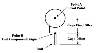
-
In some cases, this pivot point might not be the pivot point that you want to use. In these instances, the PivotOffsetCompName macro enables you to specify the component containing the desired pivot point. If “RESET” is passed as the Pivot Component Name, then this field will be reset and we will use the default pivot point.
PivotOffsetCompNameB
-
Function — TOOL OFFSETS
-
Status — ACTIVE
-
Input —
- Text: Pivot Component name (Point B)
- Value: Not Used
The TurnOnOffGagePivotOffset macro establishes a "relational" offset between a pivot point, based on the machine configuration, and the current active tool component origin. By default, Vericut will determine the pivot offset as follows:
-
- Find first rotary, turret, or gang tooling component up from the Tool. If the first rotary, turret, or gang tooling component does not exist, the pivot offset is (0,0,0).
-
- Find second rotary, turret, or gang tooling component up from the Tool. If the second rotary, turret, or gang tooling component does not exist, the pivot offset is the offset from the first rotary, turret, or gang tooling component to the Tool.
-
- If the rotation axis of the first rotary, turret, or gang tooling component intersects the rotation axis of the second rotary, turret, or gang tooling component, the pivot offset is from this intersection point to the tool.
-
- If there is no intersection, the pivot offset is from the second rotary, turret, or gang tooling component to the tool.
-
- If no rotary, turret, or gang tooling components exist on the tool side, the active tool component origin will be used. See the illustration below.
-

-
In some cases, the current active tool component origin might not produce offset from the pivot point that you want. In these instances the PivotOffsetCompNameB macro enables you to specify the name of a component whose origin is to be used instead of the active tool component origin. If “RESET” is passed as the Pivot Component Name, then this field will be reset and we will use the active tool component origin.
PlaneAxisMapping
-
Function — MAPPING
-
Status — ACTIVE
-
Input —
- Text: Not Used
- Value: Not Used
This macro initializes the mapping with the following default values:
- X axis <= => X Point
- Y axis <= => Y Point
- Z axis <= => Z Point
The <= => symbol used below represents a two way mapping. Axis to a point and point to the axis. Then depending on what motion has been called for this block, the mapping gets updated as follows.
- If U, "X-axis" will be changed to U-axis.
- If V, "Y-axis" will be changed to V-axis.
- If W, "Z-axis" will be changed to W/-axis.
- If U2, "X-axis" will be changed to U2-axis.
- If V2, "Y-axis" will be changed to V2-axis.
- If W2, "Z-axis" will be changed to W2-axis.
Note — This macro is not associated with planes. It is strictly another way to specify the mapping.
See Also — AxisMapping
PlaneAxisVectorX
-
Function — ROTATION PLANE
-
Status — ACTIVE
-
Input —
- Text: X, Y, or Z
- Value: X value
This macro sets the X value for the specified axis. The axis is specified with the text value. Valid axes are: "X", "Y, and "Z". This data can be used with WorkingPlane2Abc.
PlaneAxisVectorY
-
Function — ROTATION PLANE
-
Status — ACTIVE
-
Input —
- Text: X, Y, or Z
- Value: Y value
This macro sets the Y value for the specified axis. The axis is specified with the text value. Valid axes are: "X", "Y", and "Z". This data can be used with WorkingPlane2Abc.
PlaneAxisVectorZ
-
Function — ROTATION PLANE
-
Status — ACTIVE
-
Input —
- Text: X, Y, or Z
- Value: Z value
This macro sets the Z value for the specified axis. The axis is specified with the text value. Valid axes are: "X", "Y", and "Z". This data can be used with WorkingPlane2Abc.
PlaySoundFile
-
Function — MISCELLANEOUS
-
Status — ACTIVE
-
Input —
- Text: wav file name
- Value: Not Used
-
Comment — Added V6.0.1
-
Input —
- Text: wav file name
- Value: Not Used
When called, it plays the wav file specified in the Override Text field.
Pogo
-
Function — MISCELLANEOUS
-
Status — ACTIVE
-
Input —
- Text: RETURN= your_pogo_var_name
- Value: Not Used
-
Comment — Added V6.2
-
Input —
- Text: RETURN= variable_name_
- Value: Not Used
The Pogo macro should be called before each ProcessCompNameValue macro that triggers a pogo motion. Calling the Pogo macro marks that the motion should be processed through the new pogo-orientation logic. Calling the Pogo macro before any motion command, other than the ProcessCompNameValue macro, will have no effect.
The pogo-orientation logic makes the following assumption to determine what component is the pogo suction cup that needs to be re-oriented. Vericut starts from the component specified in the ProcessCompNameValue macro, and searches down its component branch, at each level following the branch of the 1st machine-visible child. The last such component in the branch is considered to be the pogo suction cup.
When a pogo motion is processed, Vericut takes the origin of the suction cup CSYS and ray-traces it in the direction of motion to find the closest intersection with all stock components present. If the intersection is found, the suction cup is oriented such that its Z-axis is aligned with the stock normal at the intersection.
At the same time, Vericut check for error conditions: re-orientation angle is too large, distances from suction cup to the stock intersection point that are too large (into/away stock errors), and "No stock found". The "re-orientation angle" is the difference between the suction cup "zero rotation" orientation and the surface normal at the stock intersection point. The "into" error condition is where the suction cup is above the stock intersection point ("into the stock"). The "away" error condition is where the suction cup is below the stock intersection point ("away from the stock").
Vericut will still re-orient the suction cup for all error conditions except for the "No stock found" case. The default values for the error checks are: 45 deg for the max angle, and 0.01 for the away/into tolerances. The following macros can be used to override the defaults: PogoSetMaxAngle, PogoSetAbove Tolerance), PogoSetBelowTolerance
Adding Override Text: RETURN= will save the distance between the pogo cup and the stock in the specified variable.
Example —
cgtech_macro "Pogo" "RETURN= your_pogo_var_name"
cgtech_macro "[ProcessCompNameValue](index.md#processcompnamevalue)" "Pogo_Positioner_Z" (#Z_POS)
PogoCollisionCheck
-
Function — MISCELLANEOUS
-
Status — ACTIVE
-
Input —
- Text: Parent component name
- Value: Not Used
-
Comment — Added V6.2
-
Input —
- Text: Parent component name
- Value: Not Used
The PogoCollisionCheck macro performs a check to ensure that no pogo components overlap with each other. It is a one-time static check done at the time when the macro is called. Overlapping components are reported and colored red.
Use Override Text to specify a "super-pogo" component name, i.e., the name of a component which is the parent of all the pogo components that need to be checked.
When this macro is called, it will do a one-on-one static collision check between all direct children of the "super-pogo" component, including all the sub-components of the direct children. The default tolerance ("near miss") value is 0. The PogoSetCollisionTolerance macro can be used to change the tolerance.
Notes — 1. To make the POGO presentation and performance better, it is recommended that you use the OpenGL Machine views. 2. As pogos are defined as "Other" type components, they are not visible in the Workpiece view.
PogoSetAboveTolerance
-
Function — MISCELLANEOUS
-
Status — ACTIVE
-
Input —
- Text: Not Used
- Value: Tolerance
-
Comment — Added V6.2
-
Input —
- Text: Not Used
- Value: Tolerance
The PogoSetAboveTolerance macro is used to specify the "into" tolerance value to be used by the Pogo macro when checking the distance between the suction cup origin and the closest stock intersection point. The "into" tolerance value is used for reporting error conditions where the suction cup is above the stock intersection point ("into the stock"). By default, the Pogo macro uses an "away" tolerance of 0.01. Use Override Value to specify the desired tolerance value.
PogoSetBelowTolerance
-
Function — MISCELLANEOUS
-
Status — ACTIVE
-
Input —
- Text: Not Used
- Value: Tolerance
-
Comment — Added V6.2
-
Input —
- Text: Not Used
- Value: Tolerance
The PogoSetBelowTolerance macro is used to specify the "away" tolerance value to be used by the Pogo macro when checking the distance between the suction cup origin and the closest stock intersection point. The "away" tolerance value is used for reporting error conditions where the suction cup is below the stock intersection point ("away from the stock"). By default, the Pogo macro uses an "away" tolerance of 0.01. Use Override Value to specify the desired tolerance value.
PogoSetCollisionTolerance
-
Function — MISCELLANEOUS
-
Status — ACTIVE
-
Input —
- Text: Not Used
- Value: Tolerance
-
Comment — Added V6.2
-
Input —
- Text: Not Used
- Value: Tolerance
The PogoSetCollisionTolerance macro is used to specify the collision tolerance to be used by the PogoCollisionCheck macro when checking for overlapping pogo components. By default, the PogoCollisionCheck macro uses a collision tolerance of zero. Use Override Value to specify the desired tolerance value.
PogoSetMaxAngle
-
Function — MISCELLANEOUS
-
Status — ACTIVE
-
Input —
- Text: Not Used
- Value: Maximum angle
-
Comment — Added V6.2
-
Input —
- Text: Not Used
- Value: Maximum angle
The PogoSetMaxAngle macro is used to specify the maximum angle value to be used by the Pogo macro when checking for "re-orientation angles" that are too large. The "re-orientation angle" is the difference between the suction cup "zero rotation" orientation and the surface normal at the stock intersection point. By default, the Pogo macro uses a maximum "re-orientation angle" of 45 degrees. Use Override Value to specify the desired angle.
Points2Normal
-
Function — MISCELLANEOUS
-
Status — ACTIVE
-
Input —
- Text: I variable name, J variable name, K variable name, Return Code variable name (optional)
- Value: Not used
-
Comment — Added in V8.2
-
Input —
- Text: I variable name, J variable name, K variable name, Return Code variable name (optional)
- Value: Not used
Given 3 points, set by the SetPoints macro, this macro calculates the normal. The points must be given in a clockwise manner, otherwise the normal will be reversed. An error occurs if any of the following are true:
-
- 3 points have not been previously set on this block
-
- I,J,K variable names were not specified
-
- The lines from p2 to p2 and p3 to p1 are parallel
-
If an error message will be given, and a return value of zero will be set, otherwise the unitized normal will be calculated and returned, and the return value will be set to 1.
PolarAngle
-
Function — CYLINDRICAL/POLAR
-
Status — ACTIVE
-
Input —
- Text: Not Used
- Value: Polar angle (can be called twice to set 2 angles)
This macro accepts up to 2 polar angles. A simple form of a polar command is:
-
A140 X60 This says, start at an angle of 140 degrees, and continue until you reach X60. We also support complex Siemens 840C commands in the form:
-
A110 A170 X90 Z-70 B15 B3
PolarAxisOrientationOnOff
-
Function — CYLINDRICAL/POLAR
-
Status — ACTIVE
-
Input —
- Text: Not Used
- Value: 0 = OFF(default) , 1 = ON
-
Comment — Added V8.0
-
Input —
- Text: Not Used
- Value: 0 = OFF(default) , 1 = ON
This macro turns on/off the feature of detecting the orientation of the rotary being used with Polar Interpolation.
Note — The Orientation determines which way it rotates. This is specifically useful when working on the SubSpindle, and the SubSpindle spins in the opposite direction of the main spindle.
PolarCoordAngle
-
Function — MOTION
-
Status — ACTIVE
-
Input —
- Text: Not Used
- Value: Polar angle
-
Comment — Added V7.1.4
-
Input —
- Text: Not Used
- Value: Polar angle
Sets the Polar Coordinate Angle.
PolarCoordIncAngle
-
Function — MOTION
-
Status — ACTIVE
-
Input —
- Text: Not Used
- Value: Amount to increment the previously specified polar angle
-
Comment — Added V7.1.4
-
Input —
- Text: Not Used
- Value: Amount to increment the previously specified polar angle
Increments the Polar Coordinate Angle by the specified amount.
PolarCoordIncRadius
-
Function — MOTION
-
Status — ACTIVE
-
Input —
- Text: Not Used
- Value: Amount to increment the previously specified polar radius
-
Comment — Added V7.1.4
-
Input —
- Text: Not Used
- Value: Amount to increment the previously specified polar radius
Increments the Polar Coordinate Radius by the specified amount. The resulting value must be >= 0.
PolarCoordOnOff
-
Function — MOTION
-
Status — ACTIVE
-
Input —
- Text: Not Used
- Value: 0 = Off (Default), 1 = On
-
Comment — Added V7.1.4
-
Input —
- Text: Not Used
- Value: 0 = Off (Default), 1 = On
This macro turns Polar Coordinate mode "on" and "off". This value is modal. The default is off.
PolarCoordPoleCurPos
-
Function — MOTION
-
Status — ACTIVE
-
Input —
- Text: Not Used
- Value: Not Used
-
Comment — Added V7.1.4
-
Input —
- Text: Not Used
- Value: Not Used
This macro sets the Polar Coordinate Pole position to the current local axis XYZ position.
PolarCoordPoleIncXYZ
-
Function — MOTION
-
Status — ACTIVE
-
Input —
- Text: Axis to be updated (X, Y or Z)
- Value: Amount to increment the coordinate of the Polar Pole
-
Comment — Added V7.1.4
-
Input —
- Text: Axis to be updated (X, Y or Z)
- Value: Amount to increment the coordinate of the Polar Pole
This macro is used to increment the X, Y, or Z value of the Polar Coordinate Pole position. The Text specifies what axis to update (X, Y or Z).
PolarCoordPoleOrigin
-
Function — MOTION
-
Status — ACTIVE
-
Input —
- Text: Not Used
- Value: Not Used
-
Comment — Added V7.1.4
-
Input —
- Text: Not Used
- Value: Not Used
This macro resets the Polar Coordinate Pole position to be (0,0,0).
PolarCoordPoleXYZ
-
Function — MOTION
-
Status — ACTIVE
-
Input —
- Text: Axis to be updated (X, Y or Z)
- Value: The coordinate value
-
Comment — Added V7.1.4
-
Input —
- Text: Axis to be updated (X, Y or Z)
- Value: The coordinate value
This macro sets the X, Y, or Z value of the Polar Coordinate Pole position. The Text specifies what axis to update (X, Y, Z).
PolarCoordRadius
-
Function — MOTION
-
Status — ACTIVE
-
Input —
- Text: Not Used
- Value: Radius
-
Comment — Added V7.1.4
-
Input —
- Text: Not Used
- Value: Radius
Sets the Polar Coordinate Radius. This value must be >= 0.
PolarCoordReset
-
Function — MOTION
-
Status — ACTIVE
-
Input —
- Text: Not Used
- Value: Not Used
-
Comment — Added V7.1.4
-
Input —
- Text: Not Used
- Value: Not Used
This macro turns off the Polar Coordinate mode, sets the Polar Coordinate angle to 0, sets the Polar Coordinate radius to 0, and resets the Polar Coordinate Pole position to be (0,0,0).
PolarCoordZeroRadius
-
Function — MOTION
-
Status — ACTIVE
-
Input —
- Text: Not Used
- Value: 1 – Print an error, and do not convert the values to Cartesian coordinates. (Default)
-
Comment — Added V7.1.4
-
Input —
- Text: Not Used
- Value:
- 1 – Print an error, and do not convert the values to Cartesian coordinates. (Default)
- 2 – Calculate the radius based on the distance from the current location to the pole position. If the radius is still zero, print an error, and do not convert the values to Cartesian coordinates.
- 3 – Continue processing the command using zero as the radius. This will cause a move to the pole position.
This macro specifies what to do if the Polar Coordinate radius is 0.
PolarInterpolation
-
Function — CYLINDRICAL/POLAR
-
Status — ACTIVE
-
Input —
- Text: ALL (Default) – Apply polar interpolation to all motion types.
- Value: 0 = Off, 1 = On
Use this macro to turn on, and off, polar interpolation. Polar Interpolation is being defined as the capability to use the PolarLinearAxis and the PolarRotationalAxis (by default X and C) macros to execute a linear or circular move. The input can be either Cartesian coordinates or Polar coordinates.
An Override Text value of “LINEAR” will cause RAPID motions to move the X and C axis directly, resulting in a non-straight line.
An Override Text value of “ALL” (default) will cause both LINEAR and RAPID motions (G0/G1) to be interpolated, resulting in a straight line.
The Override Text value does not apply to circular (G02/G03) motions. Circular motions will always be interpolated. Rapid motion is not interpolated as linear when rotary motion is involved. Use an Override Value of 1 to turn polar interpolation "on". Use an Override Value of 0 to turn polar interpolation "off".
Examples —
Using Cartesian coordinates: X1C1
X calls [PolarXValue](polarxvalue.md#PolarXValue)
C calls [PolarYValue](polaryvalue.md#PolarYValue)
Using Polar Coordinates: X1.4142 C45
X calls [XAxisMotion](xaxismotion.md#XAxisMotion)
C calls [CAxisMotion](caxismotion.md#CAxisMotion)
Note — The "interpolation" state (None, Polar, or Cylindrical) is supported as a conditional state, and can be displayed in the Status window.
PolarLinearAxis
-
Function — CYLINDRICAL/POLAR
-
Status — ACTIVE
-
Input —
- Text: Not Used
- Value: 1 = X (Default)
-
1 = X (Default)
- 2 = Y
- 3 = Z
- -1 = -X
- -2 = -Y
- -3 = -Z
Sets the linear axis that will be driven based on the Cartesian coordinates.
Examples —
In the XY Plane with a PolarLinearAxis of 1:
- X1Y1 would be converted to X1.4142 C45
In the XY Plane with a PolarLinearAxis of -1:
- X1Y1 would be converted to X-1.4142 C-135
PolarLogic
-
Function — CYLINDRICAL/POLAR
-
Status — ACTIVE
-
Input —
- Text: Not Used
- Value: 0 = Original Polar logic (same as PolarNewLogicOnOff OV=0)
-
Comment — Added V9.6
-
Input —
- Text: Not Used
- Value:
- 0 = Original Polar logic (same as PolarNewLogicOnOff OV=0)
- 1 = More current Polar Interpolation logic (Default – same as PolarNewLogicOnOff OV=1)
- 2 = Latest Polar Interpolation logic
This macro specifies which Polar Interpolation logic to use. Typically the latest logic should be used unless there is a problem. In most cases, no other changes are needed in the configuration to switch the Polar logic. This macro replaces PolarNewLogicOnOff. NOTE: Both macros set the same internal variable.
Option 0/1: X, Y, and Z calls PolarXValue, PolarYValue and PolarZValue. These are cartesian values which are converted to Polar and stored as the local axis position.
Option 2: X, Y, and Z calls XAxisMotion, YAxisMotion, and ZAxisMotion. These are cartesian values and stored as the local axis position. As we go to drive the machine, we convert to Polar. This option also allows the linear axis not being used with Polar to be non-zero.
Note — With Option 2, PolarXValue, PolarYValue, and PolarZValue (if still used) will call XAxisMotion, YAxisMotion, and ZAxisMotion.
PolarNewLogicOnOff
-
Function — CYLINDRICAL/POLAR
-
Status — Not Recommended
-
Input —
- Text: Not Used
- Value: 0 = use old Polar Interpolation logic
-
Comment — Added V7.1.6
-
Input —
- Text: Not Used
- Value:
- 0 = use old Polar Interpolation logic
- 1 = use new Polar Interpolation logic (Default)
- This macro should be replaced with PolarLogic. This macro specifies which Polar Interpolation logic to use. Typically the latest logic should be used unless there is a problem.
No other changes are needed in the configuration to switch the Polar logic.
PolarRotationalAxis
-
Function — CYLINDRICAL/POLAR
-
Status — ACTIVE
-
Input —
- Text: Not Used
- Value: Rotational Axis to be used
-
4 = A axis - 5 = B axis - 6 = C axis (default) - 10 = A2 axis - 11 = B2 axis - 12 = C2 axis - 16 = A3 axis - 17 = B3 axis - 18 = C3 axis
This macro specifies the rotary axis that will used when in Polar Interpolation mode. The default is 6. Typically, this macro will not need to be called unless there is a sub-spindle.
- Example -
if you want to use the sub-spindle for Polar Interpolation, and the sub spindle is C2, then call this macro with a value of 12.
PolarXIncValue
-
Function — CYLINDRICAL/POLAR
-
Status — ACTIVE
-
Input —
- Text: Not Used
- Value: The incremental Y value to be moved.
Similar to PolarXValue, except it ignores the Absolute/Incremental mode setting, and increments by the value specified.
PolarXValue
-
Function — CYLINDRICAL/POLAR
-
Status — ACTIVE
-
Input —
- Text: optional MULTIPLIER
- Value: X value
Sets the X Cartesian coordinate value for Polar Interpolation. In a special case, this macro will set the cycle depth rather than the X Cartesian coordinate value. To be interpreted as cycle depth, the following conditions must be true:
-
1. Drill Cycle mode
-
2. YX motion plane
-
3. Flag set so that XYZ sets the cycle depth
-
4. The drill cycle is set so that it gets executed on motion.
-
In either case, if the Text value is “MULTIPLIER”, the input value will be multiplied by the X Axis Multiplier.
See Also — InterpolationXValue, PolarYValue, PolarZValue, XAxisMultiplier, and CycleXyzDepth
PolarYIncValue
-
Function — CYLINDRICAL/POLAR
-
Status — ACTIVE
-
Input —
- Text: Not Used
- Value: The incremental X value to be moved.
Similar to PolarYValue, except it ignores the Absolute/Incremental mode setting, and increments by the value specified.
PolarYValue
-
Function — CYLINDRICAL/POLAR
-
Status — ACTIVE
-
Input —
- Text: Not Used
- Value: Y value
Sets the Y Cartesian coordinate value for Polar Interpolation. If cycles are active, PolarYValue also sets the cycle depth (as appropriate based on the motion plane).
See Also — InterpolationYValue, PolarXValue and PolarZValue
PolarZIncValue
-
Function — CYLINDRICAL/POLAR
-
Status — ACTIVE
-
Input —
- Text: Not Used
- Value: The incremental Y value to be moved.
Similar to PolarZValue, except it ignores the Absolute/Incremental mode setting, and increments by the value specified.
PolarZValue
-
Function — CYLINDRICAL/POLAR
-
Status — ACTIVE
-
Input —
- Text: Not Used
- Value: Z value
Sets the Z Cartesian coordinate value for Polar Interpolation. If cycles are active, PolarZValue also sets the cycle depth (as appropriate based on the motion plane).
See Also — InterpolationZValue, PolarXValue and PolarYValue
PoleDefinesCircleCenter
-
Function — MOTION
-
Status — ACTIVE
-
Input —
- Text: Not Used
- Value: 0 = No (default), 1 = Yes
-
Comment — Added V7.2.1
-
Input —
- Text: Not Used
- Value: 0 = No (default), 1 = Yes
This macro is used to specify if the Polar Pole should determine the circle center when the input is in Polar Coordinates. A value of 1 = Yes, 0 = No, and the default is No. Typically, the Polar Pole, the Polar radius, and the Polar angle determine a point. This information is converted into Cartesian coordinates, and then the block is executed. Calling this macro with a value of 1 will cause the Polar Pole to also be used as the Circle center if the command on the current line is an arc. This setting is modal.
PQRVector
-
Function — MOTION
-
Status — ACTIVE
-
Input —
- Text: P, Q, or R
- Value: Corresponding vector value
-
Comment — Added V7.1
-
Input —
- Text: P, Q, or R
- Value: Corresponding vector value
Sets the P, Q, or R values used to define the tool motion direction vector. This macro determines which value is being set (P,Q,or R) based on the “Word”. This means that this macro only works when being called by P, Q, or R Word. For example: P.7 Q.7 R0 The motion direction vector is used with composite tape laying data input created by a VCP postprocessor. The tool motion direction vector can be transformed to a user specified coordinate system.
See Also — SetRobotCsys
PreToolCompSelect
-
Function — TOOLING
-
Status — ACTIVE
-
Input —
- Text: Not Used
- Value: Tool component Index number
Stores the pre-selected tool component Index number.
Probe
-
Function — MISCELLANEOUS
-
Status — ACTIVE
-
Input —
- Text: Optionally: RETURN=var1 var2 var3 var4
- Value: Not Used
This macro turns on probing for the current block. This macro is associated with the active tool component, and the corresponding tool must be a Probe Tool. The axes move until they arrive at the programmed location, or until the probe contacts something. Once contact is made, motion is stopped and the rest of the move is aborted.
If the Override Text value begins with "RETURN=", then the string following the equal sign will be interpreted as a variable name in which the return code from the Probe motion will be returned. A return code value of 1 means that a "hit" occurred and a return code value of 0 means that a "hit" did not occur.
If four variable names are supplied then the first variable name will contain the return code, and the next three variable names are used to return the X, Y and Z coordinates of the contact point location in the stock coordinate system. The specified variable names are modal. The variable does not need to be pre-defined. The X, Y and Z positions are only recorded if the probe makes contact.
Example —
Probe OT= XPOS YPOS ZPOS
PROBE_TOUCHED would contain a 1 if the probe made contact and a 0 if it didn’t.
XPOS would contain the position value of X.
YPOS would contain the position value of Y.
ZPOS would contain the position value of Z.
See Also — MeasureCoordinates
Notes — 1. The values contained in the X, Y, Z variables reflect either the Stock Component coordinate system (default) or the active local coordinate system depending upon the setting of the MeasureCoordinates macro. 2. The Probe macro requires a CNC Machine Probing license.
ProcessCompNameFeedrate
-
Function — MOTION
-
Status — ACTIVE
-
Input —
- Text: Component name
- Value: Feedrate
-
Comment — Added in V8.2
-
Input —
- Text: Component name
- Value: Feedrate
This macro specifies the feedrate for a specific component. This feedrate is then used with the ProcessCompNameValueSync and ProcessCompNameValueSyncWait macros. This values are modal.
ProcessCompNameReset
-
Function — MOTION
-
Status — ACTIVE
-
Input —
- Text: Component name
- Value: Not Used
-
Comment — Added V7.1
-
Input —
- Text: Component name
- Value: Not Used
This macro resets the position (offset and value) of the specified component to zero. This macro was implemented for the Citizen control. Its use should be very limited. This macro should not be used for any component in the current subsystem. By default, rotary motions are not tessellated. This could cause problems with collision detection. To tesselate rotary motion, call ProcessCompNameTesselate OV=1. This can be called during the Start of Process event.
ProcessCompNameTesselate
-
Function — MOTION
-
Status — ACTIVE
-
Input —
- Text: Not Used
- Value: 0 = No (default), 1 = Yes
This macro sets a flag which is used by the ProcessCompName macros. This flag determines whether we tesselate rotary motion. The default is to not tesselate the motion. This means that if you plan to do collision checking, and you are calling one of these macros for a rotary component, you need to call this macro with a value of 1.
This macro effects the following macros:
ProcessCompNameValue
-
Function — MOTION
-
Status — ACTIVE
-
Input —
- Text: Component name
- Value: Position to move component to
Sets the position of the component whose name is specified in the input text string to the specified numeric value. This macro should not be used for any component in the current subsystem. By default, rotary motions are not tessellated. This could cause problems with collision detection. To tesselate rotary motion, call ProcessCompNameTesselate OV=1. This can be called during the Start of Process event.
ProcessCompNameValueSync
-
Function — MOTION
-
Status — ACTIVE
-
Input —
- Text: Component name
- Value: Position to move component to
-
Comment — Added in V8.2
-
Input —
- Text: Component name
- Value: Position to move component to
Similar to ProcessCompNameValue, this macro will move the specified component to the specific position. The difference with this macro, is that the motion will be executed in a separate channel. The motion will then occur in sync with all other motion this is occurring. The feedrate for this motion is specified with ProcessCompNameFeedrate. Care should be taken to insure that more than 1 channel is not driving the same component at the same time. This macro should not be used for any component in the current subsystem. By default, rotary motions are not tessellated. This could cause problems with collision detection. To tesselate rotary motion, call ProcessCompNameTesselate OV=1. This can be called during the Start of Process event.
ProcessCompNameValueSyncWait
-
Function — MOTION
-
Status — ACTIVE
-
Input —
- Text: Component name
- Value: Position to move component to
-
Comment — Added in V8.2
-
Input —
- Text: Component name
- Value: Position to move component to
This macro will move the specified component to the specified position. This macro is identical to ProcessCompNameValueSync, except at the end of the block, the system will wait until this motion is complete before processing the next block. For example: On a block we are told to move X 10 inches at 10 inches/min. We are also told (with this command) to move a fixture 20 inches at 5 inch/min. The X and the fixture motion will start at the same time. The X motion will finish first (the fixture had only moved 5 inches). The system will now wait for the system to finish moving the fixture before continuing with the next block. The feedrate for this motion is specified with ProcessCompNameFeedrate. Care should be taken to insure that more than 1 channel is not driving the same component at the same time. This macro should not be used for any component in the current subsystem. By default, rotary motions are not tessellated. This could cause problems with collision detection. To tesselate rotary motion, call ProcessCompNameTesselate OV=1. This can be called during the Start of Process event.
ProcessCompRegValue
-
Function — MOTION
-
Status — ALTERNATE
-
Input —
- Text: Register Value of Component (X,Y,Z,U,V,W)
- Value: Position to move component to
-
Comment — Use ProcessCompNameValue
-
Input —
- Text: Register Value of Component (X,Y,Z,U,V,W)
- Value: Position to move component to
Sets the position of the component whose register value is specified in the input text string to the specified numeric value. This macro should not be used.
ProcessCutterComp
-
Function — CUTTER COMPENSATION
-
Status — NOT RECOMMENDED
-
Input —
- Text: Not Used
- Value: 0 = Off
-
Comment — Added V7.1
-
Input —
- Text: Not Used
- Value:
- 0 = Off
- 1 = On default to zero
- 2 = On default to full radius
This macro is used to override to the Process Cutter Comp feature setting in the Project Tree, Configure Setup menu: G-Code tab. The Process Cutter Comp feature now defines the Default setting for the setup, which can now be overridden for a specific control (otherwise known as subsystem or channel) by calling this macro. This macro value does not change the Process Cutter Comp feature setting, and is not saved in the Project file.
Note — This macro's values match the options on the Process Cutter Comp feature options in the Project Tree, Configure Setup menu: G-Code tab. By calling this macro, it makes it easier to mis-configure the control. For this reason, the use of this macro is "not recommended". It is, however, available if needed for special situations.
ProcessCutterCompRestore
-
Function — CUTTER COMPENSATION
-
Status — NOT RECOMMENDED
-
Input —
- Text: Not Used
- Value: Not Used
-
Comment — Added V7.1
-
Input —
- Text: Not Used
- Value: Not Used
This macro restores the cutter compensation setting to the value that was active prior to the last call to ProcessCutterComp. If ProcessCutterComp has not been called since the last reset, this macro will have no effect.
See Also — ProcessCutterComp
ProcessLandisCamshaftLobeFile
-
Function — MISCELLANEOUS
-
Status — ACTIVE
-
Input —
- Text: Filename X_offset C_offset
- Value: Not Used
This macro is used to process a Camshaft Lobe File on a Landis control.
The format of the file is:
- M     ; ignored
- P     ; ignored
- Process Data Import   ; Comment, ignored
- 28.575000     ; Follower radius, ignored
- 41.281000     ; Base radius
- 0.000000000,359.000000000,1.000000000     ; Start angle, End angle, Increment angle
- 0.0,0.0   ; Ignored
- 12.960853071  ; A series of lines specifying the X position for each angle
- 12.956731944
- 12.944318930
- ...
Using the Start_angle, End_angle, and Increment angle, the macro will process each motion.
It will call [XAxisMotion](index.md#xaxismotion) and [CAxisMotion](index.md#caxismotion) for each line.
For [XAxisMotion](index.md#xaxismotion), it will pass the value read + the Base Radius + the X offset.
For [CAxisMotion](index.md#caxismotion), it will pass the angle + the C offset.
Note — The X position is not exact, but it is close. Currently, we do not know the algorithm to calculate the exact X position.
ProcessMotion
-
Function — EVENTS
-
Status — ACTIVE
-
Input —
- Text: Not Used
- Value: Not Used
Processes the motion associated with the previous set of commands. This command is automatically called at the end of the block. This command can also be called as a macro to create additional motion.
ProcessOpSubstitutions
-
Function — OPTIMIZATION
-
Status — ACTIVE
-
Input —
- Text: Not Used
- Value: 1 = Only apply to Optimized lines (Default)
-
Comment — Added V7.3.1
-
Input —
- Text: Not Used
- Value:
- 1 = Only apply to Optimized lines (Default)
- 2 = Apply to all lines.
This macro defines when Optimization Substitutions (Advanced Control Options window: Optimization Subsitute tab) should be used.
Note — In order to get Sin840D jobs working with Optimization, we modified the logic to only apply the Optipath Substitutions to lines that were being optimized (and not lines that were just being passed through). This became the default logic. This macro allows you to override the default logic, and apply the Optipath Substitutions to all lines. This setting is modal, and this macro would generally be called during start of processing. It is channel (subsystem) independent. This macro should not be used with Sin840D controls.
ProcessTimeOnOff
-
Function — MISCELLANEOUS
-
Status — ACTIVE
-
Input —
- Text: Not Used
- Value: 0 = Off, Any other value = On
Turns machining time On and Off during toolchain operations. This allows the system to ignore times from tool changer motions and only use the exact exchange time defined in the toolchain component dialog. A value of zero turns time off, and a value of one turns time back on.
ProgramStartNextLine
-
Function — MISCELLANEOUS
-
Status — ACTIVE
-
Input —
- Text: Not Used
- Value: Not Used
Marks the following block as the first block of the program. This is used when the beginning of a file contains subroutines followed by a specific code which marks the beginning of the program.
ProjectUnitsVar
-
Function — VARIABLES
-
Status — ACTIVE
-
Input —
- Text: Variable name
- Value: Not Used
-
Comment — Added V7.1
-
Input —
- Text: Variable name
- Value: Not Used
This macro is used to define a variable to hold the current Project's Units: Inch or Millimeter. Enter the name for the variable to be defined in the Override Text field. The current Project's Units are stored in the variable with a value of "0" for Inch or a value of "1" for Millimeter.
RadialToolArmLength
-
Function — INTERPOLATION
-
Status — ACTIVE
-
Input —
- Text: Not Used
- Value: Arm Length
-
Comment — Added V7.3.3
-
Input —
- Text: Not Used
- Value: Arm Length
This macro sets the arm length this is used with RADIAL TOOL interpolation. In this interpolation mode, the A axis on the tool is rotated to allow for a small movement in the Y direction. The formula is: Y = SIN(HEAD ANGLE) * Arm Length.
RadialToolInterpolation
-
Function — INTERPOLATION
-
Status — Active
-
Input —
- Text: LINEAR = Apply this interpolation only to non-RAPID moves (default)
- Value: 0 = Turns this interpolation state off (default)
-
Comment — Added V7.3
-
Input —
- Text: LINEAR = Apply this interpolation only to non-RAPID moves (default)
- Value:
- 0 = Turns this interpolation state off (default)
- 1 = Turns this interpolation state on
- This macro turns on and off Radial Tool Interpolation. This interpolation mode was created special for a machine without a Y axis, which used arm length of a right angle tool to create the Y motion.
See also — RadialToolArmLength
RadiusDeltaPerRev
-
Function — CIRCLES
-
Status — ACTIVE
-
Input —
- Text: Not Used
- Value: Radius delta value.
-
Comment — Added V7.3.4
-
Input —
- Text: Not Used
- Value: Radius delta value.
This macro is used to support the Q-parameter for Fanuc spiral interpolation motion. A spiral motion can be set with the Q-parameter, for example:
-
G02X2.26Y0.I-29.96J0Q2.5F120.
-
In this example the Q-parameter specifies that the spiral is adding 2.5 units to the radius per each 360-degree revolution. To support this, the macro RadiusDeltaPerRev should be called with a radius delta value of 2.5. The radius delta value is then used to calculate the shape of the spiral, including the required number of revolutions.
-
If the specified radius delta value does not match the other spiral parameters (start and end radii, and the angle difference between the start and end points) a warning similar to "Invalid spiral statement. Final radius 2.26, calculated value 3.96" is output. In the case of a mismatch a valid spiral motion is output with the radius delta adjusted to match the spiral parameters. The calculated value has the best matching number of full loops.
RapidInterpolationWarningOnOff
-
Function — MOTION
-
Status — ACTIVE
-
Input —
- Text: Not Used
- Value: 0 = OFF (Default), 1 = ON
-
Comment — Added 9.6
-
Input —
- Text: Not Used
- Value: 0 = OFF (Default), 1 = ON
This macro determines if we output a Warning message if we process a RAPID move, with RTCP or RPCP turned on, and the motion is not interpolated. With RAPID moves, the moves might not be interpolated. See Axis Priority table. This means that different Axes might have different priorities. For example: Move X and Y first, and then move Z. Or the Axis might be marked as non-Interpolated. With RTCP/RPCP we are trying to maintain the tool to part position while the rotaries rotate. This is not possible if the axis are not interpolated. This macro determines if we should give a Warning in this situation.
Note — You should makes sure your settings in the Axis Priority table matches the machine you are trying to simulate.
RapidPlanePriorityType
-
Function — MISCELLANEOUS
-
Status — ACTIVE
-
Input —
- Text: Not Used
- Value: 0 = Rapid is not dependent on active plane. (Default)
-
0 = Rapid is not dependent on active plane. (Default)
- 1 = Rapid is dependent on active plane.
Supports the concept of the motion of a rapid move being dependent on the plane rather than the machine axis. To turn on this capability, this macro should be called during the "Start of Processing" event with an Override Value of 1.
With this macro set to 1, the Rapid motions will be:
-
Movement to workpiece: rotaries, then linear in plane, then normal to plane
-
Movement away from workpiece: normal to plane, the linear in plane, then rotaries
Note — If motion is set to be dependent on active plane, the rapid priority axis should probably be set to moving at the same time with all axis interpolated.
RapidRotaryTolerance
-
Function — MOTION
-
Status — NOT RECOMMENDED
-
Input —
- Text: Not Used
- Value: Tolerance value
-
Comment — Added V7.1
-
Input —
- Text: Not Used
- Value: Tolerance value
This macro overrides the Rotary Motion Tolerance value, specified on the Properties window: Tolerance tab, when in RAPID mode. The tighter the tolerance, the higher the performance hit. The assumption is, if you are in RAPID mode, you are far enough from everything that there should never be a collision, therefore loosen the tolerance in order to gain performance. Two possible problems exist with using the above macro. 1. The assumption that you are far away from everything is not necessarily true. 2. The performance hit is much less now than in V7.0 For the above reasons, it is recommended that this macro not used. It is added for the cases where it is absolutely needed for performance reasons.
Rcode
-
Function — CIRCLES
-
Status — ALTERNATE
-
Input —
- Text: Not Used
- Value: Circle Radius or Rapid level
-
Comment — Use Conditionals to call macros directly.
-
Input —
- Text: Not Used
- Value: Circle Radius or Rapid level
Depending on the motion type (circular or non-circular), either sets the radius of a circle, or sets the R point level of a cycle. For a circle the interpretation of the center point is dependent on the Circles control settings (ref. Control Settings window: Circles tab in the Vericut Help section, in the Vericut Help Library).
ReferencePoint
-
Function — MISCELLANEOUS
-
Status — ACTIVE
-
Input —
- Text: Not Used
- Value: Not Used
This macro is used to move all axis specified on the block to the machine locations specified by the Machine Reference Location table. The Machine Reference Retraction table is used to specify which of the axis specified on the block should be moved and in what order (0,1,2,3). Zero means to not move this axis. The value of 1,2,3 specifies the order as first, second, or third. If the Machine Reference Retraction table is not specified, all axis specified on the block will be moved at the same time. This macro uses Register 1 for both tables.
Note — Travel limit warnings are disable during the move to the reference point move.
ReferencePointCancelOffsets
-
Function — MISCELLANEOUS
-
Status — ACTIVE
-
Input —
- Text: Not Used
- Value: Not Used
Causes a return to the machine reference point for the XYZ axes specified on the block. This action occurs after block motion has been processed. The corresponding work and shift offsets for the specified axis are also reset to 0.
ReferencePointDirect
-
Function — MISCELLANEOUS
-
Status — ACTIVE
-
Input —
- Text: ERROR, ERROR_NO_MOTION, and NO_ERROR_NO_MOTION
- Value: Index into the Machine Reference Location table
-
Comment — Added 7.1
-
Input —
- Text: ERROR, ERROR_NO_MOTION, and NO_ERROR_NO_MOTION
- Value: Index into the Machine Reference Location table
This macro is used to move all axes to the machine locations specified by the Machine Reference Location table. The Machine Reference Retraction table is used to specify which axes to move and in what order (0,1,2,3). Zero means to not move this axis. The value of 1,2,3 specifies the order as first, second, or third. If the Machine Reference Retraction table is not specified, all axis will be moved at the same time. The input Value is used to specify the index into both tables.
By default, if the table entry does not exist in the Machine Reference Location table, all axis to be moved will be moved to zero with no error. This behavior can be overridden with the Text argument:
-
ERROR: Produce an error, and drive the machine to zero
-
ERROR_NO_MOTION: Produce an error, and do not move the machine
-
NO_ERROR_NO_MOTION: Do not produce and error, and do not move the machine
Note — A rotated coordinate system is only supported for X,Y, and Z.
ReferencePointIndex
-
Function — MISCELLANEOUS
-
Status — ACTIVE
-
Input —
- Text: Not Used
- Value: Not Used
This macro is the same as ReferencePoint except the input Value specifies the Register for both the Machine Reference Location table and the Machine Reference Retraction table. This macro is used to move all axis specified on the block to the machine locations specified by the Machine Reference Location table. The Machine Reference Retraction table is used to specify which of the axis specified on the block should be moved and in what order (0,1,2,3). Zero means to not move this axis. The value of 1,2,3 specifies the order as first, second, or third. If the Machine Reference Retraction table is not specified, all axis specified on the block will be moved at the same time.
Note — Travel limit warnings are disable during the move to the reference point move.
RefreshToolOffset
-
Function — TOOL_OFFSETS
-
Status — ACTIVE
-
Input —
- Text: Not Used
- Value: Not Used
-
Comment — Added V6.2.1
-
Input —
- Text: Not Used
- Value: Not Used
This macro causes the tool offsets to be recalculated using the current settings and tool orientation.
RefreshWorkShiftOffsets
-
Function — SHIFT WORK PZ
-
Status — ACTIVE
-
Input —
- Text: Not Used
- Value: Not Used
This macro causes the Base, Work, Shift, and Program Zero offsets to be recalculated using the current settings.
RegisterMapping
-
Function — MAPPING
-
Status — ACTIVE
-
Input —
- Text: RESET or Register (X,Y,Z,U,V,W)
- Value: Not Used
-
Comment — Added V6.2.1
-
Input —
- Text: RESET or Register (X,Y,Z,U,V,W)
- Value: Not Used
Typically, the input text value will be a register (X, Y, Z, U, V and W). The software will then look to see which axis the corresponding component travels along. This register axis will then be mapped to the corresponding motion axis. The <= => symbol used below represents a two way mapping. Axis to a point coordinate and point coordinate back to the axis.
If a text value of "RESET" is specified, the mapping flags will be reset to their default values. The default values are:
-
X axis <= => X Point
-
Y axis <= => Y Point
-
Z axis <= => Z Point
Example —
-
If you start with a default mapping, and then call this macro with a text value of "V", and V moves along the Z axis, the mapping flags will be modified to have the V axis value set the Z point.
-
X axis <= => X Point
-
Y axis <= => Y Point
-
V axis <= => Z Point
See Also — AxisMapping, AxisMappingXtoU, CirclePresentAxis, and PlaneAxisMapping. Note — The register corresponds to the "Component Type" field within a Component.
RelationalOffsetRegisterName
-
Function — TOOL_OFFSETS
-
Status — ACTIVE
-
Input —
- Text: RESET or Register (X,Y,Z,U,V,W)
- Value: Not Used
-
Comment — Added V7.0
-
Input —
- Text: RESET or Register (X,Y,Z,U,V,W)
- Value: Not Used
This macro has been created as an alternative way to specify the component in which a relational offset should be applied. Rather than calling one of the RelationalOffsetCompName macros (XRelationalOffsetCompName, YRelationalOffsetCompName, ZRelationalOffsetCompName) this macro can be called to specify the Register name that you want the offset to apply to. For example: If your machine is defined with both X and U register components, both moving along the X-axis, if you call this macro with an OT=U, then the X relational offset will be applied to the U register component. If a text value of "RESET" is specified, the direct specification of the registers used for X, Y, Z Relational offsets will be deleted, and the software will apply X to X, Y to Y and Z to Z. Important Limitation: During the reset, the Machine Zero Offset, the Program Zero Offset, the Base Work Offset, and the default Work Offset is set. This occurs prior to the "Reset" event. This means that these macros will not affect the initial settings of these offsets.
See also — XRelationalOffsetCompName, YRelationalOffsetCompName, and ZRelationalOffsetCompName Note — Calling UpdatePZ after ZRelationalOffsetCompName could be used to force the update of the Program Zero offset.
RelationalOffsetsLocationUpdate
-
Function — SUBROUTINES
-
Status — ACTIVE
-
Input —
- Text: U, V, or W
- Value: Not Used
This macro will update the “Calculate Relative to Location” of Base and Work Offsets based on the current location of the specified axis. The delta adjustment of the specified axis is then applied to the “Translate to Location” of the X/Y/Z axis.
Note — This change is immediately applied to the Base Work Offset, and all Work Offsets.
RelationalOffsetUVWOption
-
Function — TABLES
-
Status — ACTIVE
-
Input —
- Text: Not Used
- Value: 1 = UVW are always just additional offset (default
-
Comment — Added V9.2.1
-
Input —
- Text: Not Used
- Value:
- 1 = UVW are always just additional offset (default
- 2 = Use the total offset, and apply the delta to the Translate TO Location
This macro gives an option on how we process UVW values when being applied to Relational Offsets.
RelationalTablesRefresh
-
Function — TABLES
-
Status — ACTIVE
-
Input —
- Text: Not Used
- Value: Not Used
-
Comment — Added V9.2
-
Input —
- Text: Not Used
- Value: Not Used
This macro causes all relational tables to be recalculated/refreshed. This can be useful after a mount, in which the component tree changes.
RelativeToDrivenSubsystem
-
Function — MACRO_WORK_OFFSETS
-
Status — ACTIVE
-
Input —
- Text: None
- Value: 0 = Do not move rotary components with * SubSystem (default), 1= Move all rotary components
-
Comment — Added V8.1
-
Input —
- Text: None
- Value: 0 = Do not move rotary components with * SubSystem (default), 1= Move all rotary components
When relational offsets are defined, the following information is supplied:
-
From
-
To
-
Translate To Location
-
Calculate Relative to Location
-
Additional Offset
-
When we calculate the offset, we first move the machine to the orientation specified with “Calculate Relative to Location”. If “Calculate Relative to Location” was set to C90, this means to move all axis to zero except for C, and to move C to 90. These axis positions corresponds to components on the current SubSystem.
-
By default, if the component’s SubSystem was defined as “”, then this component would not be moved when calculating the offset. By calling this macro with a value of 1, rotary components with a “” SubSystem will also be moved.
Note — The “Calculate Relative to Location” does not apply when calculating offset based on the current orientation of the rotaries (Dynamic Work Offset).
RenameStocksToDesign
-
Function — MISCELLANEOUS
-
Status — ACTIVE
-
Input —
- Text: Component name
- Value: Not Used
-
Comment — Added V6.1.1
-
Input —
- Text: Component name
- Value: Not Used
When called at the End Of Processing event, this macro traverses the Component Tree looking for stock components that contain a cut stock. For each cut stock, the stock component is renamed based on the Override Text string plus the name of the first child design component of that stock component. If no design component, then the stock component is not renamed. For example, if StockCut-1 has DesignCut-4 child, and the Override Text string is "Finish", then the new stock component name is "FinishDesignCut-4". These new names can be viewed by right clicking in the workpiece view and looking at the Attach Component pull-down list. This enables you to recognize, and select, them prior to doing an AUTO-DIFF compare. Any stock component that does not have a cut stock or does not have a design is not renamed.
RepaintCutColor
-
Function — MISCELLANEOUS
-
Status — ACTIVE
-
Input —
- Text: Not Used
- Value: Not Used
-
Comment — Added V6.2
-
Input —
- Text: Not Used
- Value: Not Used
Repaints cut stock back to original cut colors after a "Reset Cut Color" operation or, a call to the ResetCutColor macro.
See Also — ResetCutColor and SetCutColor
RepeatLoopCount
-
Function — BRANCHING
-
Status — ACTIVE
-
Input —
- Text: Not Used
- Value: Loop count
Use to set the Repeat loop count. This macro is to be used with BlockBeginLabel/BlockEndLabel macros. This macro must be called after BlockEndLabel.
ReportExpressionErrorsOnOff
-
Function — MISCELLANEOUS
-
Status — ACTIVE
-
Input —
- Text: Not Used
- Value: 0 = Off (default), 1 = On
-
Comment — Added in V8.2
-
Input —
- Text: Not Used
- Value: 0 = Off (default), 1 = On
This macro turns on and off the reporting of an error that occurs when we are unable to evaluate an expression. When reported, the error is: "Problem evaluating expression." An expression is something like: (2 + 3) or (#1 x #2). In a simple block you might have: N100 X10. N and X are words which are followed by an expression that evaluates to a single value. Examples of blocks that would create errors are:
-
R1 2
-
R(1 + 2)3
-
R(var[5]) - where var is a variable, but is not an array variable.
Note — Typically, you always want to turn this feature on. The only reason why the default if off is to remain compatible with previous releases.
ReportInvalidCharsErrorsOnOff
-
Function — MISCELLANEOUS
-
Status — ACTIVE
-
Input —
- Text: Not Used
- Value: 0 = Off (default), 1 = On
-
Comment — Added in V8.2
-
Input —
- Text: Not Used
- Value: 0 = Off (default), 1 = On
This macro turns on and off the reporting of invalid characters being read from the input file (program/subroutine file). An invalid character is being defined as a character that is not being processed in any way. This macro should be called during the Reset event. By doing so, you will get a report of all lines with invalid characters when the files are scanned. During the scan pass, single message will be produced for each line that includes invalid characters. During the run pass, an error message will be produced each time a line is processed that contains an invalid character.
ResetComponentColor
-
Function — MISCELLANEOUS
-
Status — ACTIVE
-
Input —
- Text: Component name
- Value: Not Used
-
Comment — Added V7.4
-
Input —
- Text: Component name
- Value: Not Used
Use this macro to reset the color of the component, specified in the Override Text field, to its original color.
ResetCutColor
-
Function — MISCELLANEOUS
-
Status — ACTIVE
-
Input —
- Text: Not Used
- Value: Not Used
-
Comment — Added V6.2
-
Input —
- Text: Not Used
- Value: Not Used
Resets all cut stock cuts to single color. Equivalent to operation "Reset Cut Color" in Color window, Assign tab (ref. Color window: Assign tab, in the Vericut Help section, in the Vericut Help Library).
See Also — RepaintCutColor and SetCutColor
ResetIfCheck
-
Function — BRANCHING
-
Status — ACTIVE
-
Input —
- Text: Not Used
- Value: Not Used
-
Comment — Added V6.0
-
Input —
- Text: Not Used
- Value: Not Used
This macro resets the IfCheck condition to TRUE.
ResetRotaryOffsets
-
Function — WORK OFFSETS
-
Status — ACTIVE
-
Input —
- Text: Not Used
- Value: Not Used
-
Comment — Added V7.2.1
-
Input —
- Text: Not Used
- Value: Not Used
This macro will cause the Base Work Offset, the Work Offset, the Secondary Work Offset, the Shift Offsets and the Program Zero offset to reset to their initial values. These offsets can be updated based on Dynamic Work Offset, which means that they get adjusted based on the rotation of the part. For relational offsets, the offsets will be updated based on the machine being rotated to their “Calculate Relative to Location” settings. For non-relational offsets, the offsets will be updated based as if the machine was rotated to zero.
Note — There is no motion that occurs based on this macro call. The machine axis values will be updated so that their value plus their new offset value will be equal to the previous machine axis position.
ResetScanSubsystemID
-
Function — MISCELLANEOUS
-
Status — ACTIVE
-
Input —
- Text: Not Used
- Value: Not Used
For many multi-channel jobs, there is often a code that specifies that this section of code is for channel 1 only, or for channel 2 only. For example: for Mazak, G109L1 specifies that this section of code is for channel 1, and G109L2 is for channel 2. This macro is used to specify that the following section of code is for either channel.
ResetWorkCoordParms
-
Function — SHIFT WORK PZ
-
Status — ACTIVE
-
Input —
- Text: Not Used
- Value: Not Used
The WorkCoord...Value macros set a flag indicating that a value has been specified for the corresponding axis. These flags are reset (to not present) on each block. This macro is also used to reset these flags. This macro only needs to be called if the control allows multiple sets of Work Coordinate values to be specified on a single block. This macro was specifically implemented for the G&L control.
RestoreChangeSubsystemID
-
Function — MISCELLANEOUS
-
Status — ACTIVE
-
Input —
- Text: Not Used
- Value: Not Used
-
Comment — Added V6.2
-
Input —
- Text: Not Used
- Value: Not Used
Restores the subsystem that the current control drives to the one that was active prior to calling ChangeSubsystemID.
Note — This routine calls ChangeSubsystemID to activate the change.
RestoreDWO
-
Function — MISCELLANEOUS
-
Status — ACTIVE
-
Input —
- Text: Not used
- Value: Not used
-
Comment — Added in V9.2
-
Input —
- Text: Not used
- Value: Not used
This macro restores the DynamicWorkOffset (DWO) to its last setting. This allows you to change the setting, and then restore the last setting without knowing whether the last setting was on or off.
RestoreFeedRate
-
Function — FEEDS and SPEEDS
-
Status — ACTIVE
-
Input —
- Text: Not Used
- Value: Not Used
This macro restores the previous feedrate. It does this by calling the FeedRate macro with the previous feedrate value.
Note — Every time the FeedRate macro is called, it saves the previous feedrate value. For example:
RestoreMotionType
-
Function — MOTION
-
Status — ACTIVE
-
Input —
- Text: Not Used
- Value: Not Used
-
Comment — Added V7.0
-
Input —
- Text: Not Used
- Value: Not Used
This macro restores the motion type to the last non-rapid motion. This macro is only applicable when in RAPID mode, and you want to switch back to the previous non-RAPID mode. If the current motion type is set to something other then RAPID, this macro does not restore a previous mode, and will keep the current motion type.
RestorePrevMotionType
-
Function — MOTION
-
Status — ACTIVE
-
Input —
- Text: Not Used
- Value: Not Used
-
Comment — Added V7.0
-
Input —
- Text: Not Used
- Value: Not Used
This macro is used to restore the previous motion type.
Note — Commands like ToolChange, CyclesExecute and CyclesCancel may change the motion type.
RestoreRpcp
-
Function — RPCP
-
Status — ACTIVE
-
Input —
- Text: Not used
- Value: Not used
-
Comment — Added in V9.2
-
Input —
- Text: Not used
- Value: Not used
This macro restores the RPCP to its last setting. This allows you to change the setting, and then restore the last setting without knowing whether the last setting was on or off.
Note — The RPCP can be set with the following macros: RpcpOn, RpcpOff, RotaryControlPointOnOff
RestoreRtcp
-
Function — MISCELLANEOUS
-
Status — ACTIVE
-
Input —
- Text: Not used
- Value: Not used
-
Comment — Added in V9.2
-
Input —
- Text: Not used
- Value: Not used
This macro restores the RTCP to its last setting. This allows you to change the setting, and then restore the last setting without knowing whether the last setting was on or off.
Note — The RTCP can be set through the GUI or with the following macros: RtcpOn, RtcpOff, RotaryControlPointOnOff
RestoreSavedMotionType
-
Function — MOTION
-
Status — ACTIVE
-
Input —
- Text: Not Used
- Value: Not Used
-
Comment — Added V7.0
-
Input —
- Text: Not Used
- Value: Not Used
This macro restores the "saved motion type". The "saved motion type" is set by calling the SetSavedMotionType macro.
RestoreSetSubsystemID
-
Function — MISCELLANEOUS
-
Status — ACTIVE
-
Input —
- Text: Not Used
- Value: Not Used
-
Comment — Added V6.2
-
Input —
- Text: Not Used
- Value: Not Used
Restores the active subsystem (control) to the one that was active prior to calling SetSubsystemID.
Notes — 1. This routine calls SetSubsystemID to activate the change. 2. This macro replaces RestoreSubsystemID (name change). RestoreSubsystemID is now OBSOLETE.
RestoreSubsystemID
-
Function — MISCELLANEOUS
-
Status — OBSOLETE
-
Input —
- Text: None
- Value: None
-
Comment — Replaced by RestoreSetSubsystemID
RestoreUnits
-
Function — MISCELLANEOUS
-
Status — ACTIVE
-
Input —
- Text: Not Used
- Value: Not Used
Restores the units to the previous saved value.
See Also — SaveUnits.
RestrictRotaryAxis
-
Function — ROTATION PLANE
-
Status — ACTIVE
-
Input —
- Text: FIRST = use the working plane rotation axis closest to the tool (carrier) (Default)
- Value: Angle at which the rotary axis angular space is to be divided
-
Comment — Added V6.2
-
Input —
- Text: FIRST = use the working plane rotation axis closest to the tool (carrier) (Default)
- Value: Angle at which the rotary axis angular space is to be divided
Use to specify the working plane rotation axis that is to be used to determine which of two possible solutions should be used. This macro enables overriding the current logic used for Heidenhain controls where the nearest axis to the tool is used. If Override Text is FIRST (the default), the working plane rotation axis closest to the tool (carrier) is used to determine the solution. If Override Text is SECOND, the second working plane rotation axis (rider) will be used to determine the solution. The Override Value is used to specify an angle at which the rotary axis angular space is to be divided. The Value option was developed to support the Siemens 840D CYCLE800 subroutine and is only valid for use with macro WorkingPlane2AbcSolution, types 4 (Use the small value solution for the specified rotary axis) and 5 (Use the large value solution for the specified rotary axis). The solution for the restricted axis is selected based on the absolute position of that axis (i.e., is not related to the previous axis value like it is with all other options). If no Override Value is entered, or a value of "0" is entered, this macro processes as described above for Override Text.
See Also — WorkingPlane2AbcSolution
RetractLevelClearanceRetract
-
Function — DRILL CYCLES
-
Status — OBSOLETE
-
Input —
- Text: None
- Value: None
RetractLevelInitial
-
Function — DRILL CYCLES
-
Status — OBSOLETE
-
Input —
- Text: None
- Value: None
RetractLevelRpoint
-
Function — DRILL CYCLES
-
Status — OBSOLETE
-
Input —
- Text: None
- Value: None
RetractLevelSpecifiedpoint
-
Function — DRILL CYCLES
-
Status — OBSOLETE
-
Input —
- Text: None
- Value: None
ReturnFromSub
-
Function — SUBROUTINES
-
Status — ACTIVE
-
Input —
- Text: Not Used
- Value: Not Used
This macro is identical to EndSub, except it does not mark the current location as the end of the subroutine. This allows for multiple "returns" from a given subroutine.
Note — If this macro is called rather than EndSub, there will need to be some other event to mark the end of the subroutine.
ReturnFromSubCall
-
Function — SUBROUTINES
-
Status — ACTIVE
-
Input —
- Text: Not Used
- Value: Not Used
-
Comment — Added V6.0
-
Input —
- Text: Not Used
- Value: Not Used
This macro is identical to ReturnFromSub, except it will only be executed if you are currently with a subroutine.
RobotOffsetOnOff
-
Function — MISCELLANEOUS
-
Status — ACTIVE
-
Input —
- Text: Origin for robot offset measurements
- Value: 0 = Off, 1 = On
-
Comment — Added in V8.2
-
Input —
- Text: Origin for robot offset measurements
- Value: 0 = Off, 1 = On
This macro enables (ON) and disables (OFF) the robot offset mode, the sum of all offsets ($P_ACTFRAME) must be set initially as the distance from the measurement origin (set in Text) to part program zero, when robot is in zero configuration. Robot Program Zero CSYS will then be automatically managed during simulation (using offsets).
If Text is not set, the log will show the following message: “Robot offset origin component specified in RobotOffsetOnOff does not exist; default FROM_TOOL origin will be used.”; simulation will then use the default behavior, by measuring offsets from tool.
This macro must only be called once, in Event “Reset”, before any of the following macros (if existing): SetRobotBaseCsys, SetRobotTipCsys, SetRobotCsys.
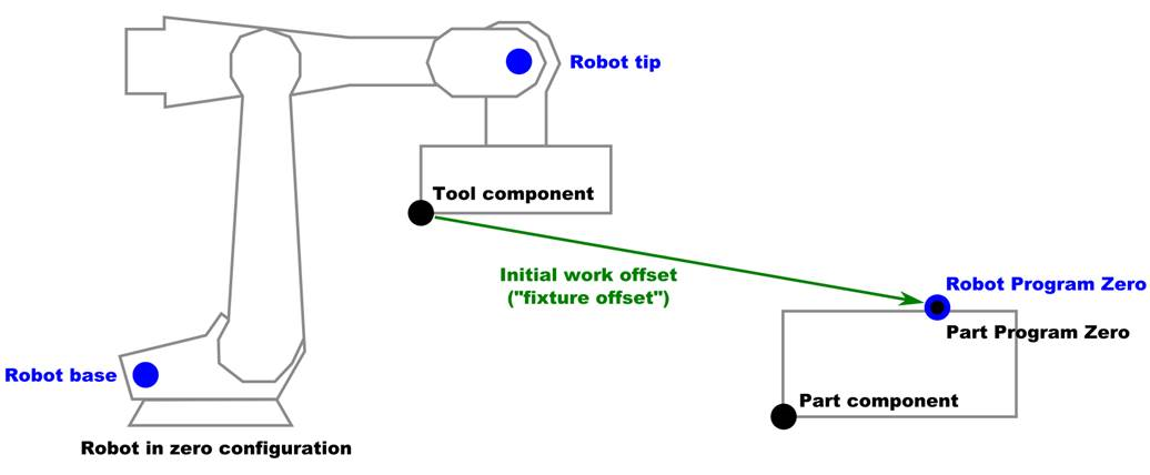 Robot Program Zero CSYS (associated to robot offset mode) is fully internal.
It is still possible to see its location in the 3D view, by using Driven Point Zero.
If there is an update associated to offsets, internal logic ensures that Robot Program Zero CSYS gets regenerated implicitly.
Except if Dynamic Work Offsets (DWO) are activated: DWO may be related to rotations, and there is no safe and trivial way to add standard and dynamic offsets together; Implicit regeneration is disabled in this very particular case.
A call to macro GenerateRobotPartCSYS allows forcing the (re)generation of Robot Program Zero CSYS (no need to set associated Value/Text).
Robot Program Zero CSYS (associated to robot offset mode) is fully internal.
It is still possible to see its location in the 3D view, by using Driven Point Zero.
If there is an update associated to offsets, internal logic ensures that Robot Program Zero CSYS gets regenerated implicitly.
Except if Dynamic Work Offsets (DWO) are activated: DWO may be related to rotations, and there is no safe and trivial way to add standard and dynamic offsets together; Implicit regeneration is disabled in this very particular case.
A call to macro GenerateRobotPartCSYS allows forcing the (re)generation of Robot Program Zero CSYS (no need to set associated Value/Text).
Note — It is possible to apply and keep a specific rotation the active part component (this functionality is only present for legacy purpose). This is done by using macro SetRobotCsys (which is not mandatory anymore, when using Robot Offset mode). The rotation part of the CSYS component pointed by this macro will be applied to the active part component. Rotations of the programmed point/vector can be applied, by using rotation planes and/or Siemens frames. All associated transformations are applied during robot movement processing.
A rotation can be applied to the programmed points/vectors, by:
-
- Using rotation planes and/or Siemens frames.
-
- Setting a rotation inside Robot Base (directly associated to local orientation of machine component or CSYS component).
-
- Setting a rotation inside a CSYS component, and point it with a call to macro SetRobotCsys.
RoedersForLoop
-
Function — BRANCHING
-
Status — ACTIVE
-
Input —
- Text: The full MCD command starting with the variable name
- Value: Not used
-
Comment — Added V9.2
-
Input —
- Text: The full MCD command starting with the variable name
- Value: Not used
This macro defines a "FOR" loop for a Roeders control. This macro is used to process a "FOR" loop of the following form:
-
DO=5
-
...
-
ENDDO
-
Or
-
DO=variable_name=expression;expression;expression
-
…
-
ENDDO
-
In the second case, the expressions are the initial value, final value, and incremental value The incremental value is the amount the variable should be incremented by (positive or negative) on each loop.
Note — When defining the DO Word in the Word table, the Sub Type should be set to: Text, Remainder of Line
RollerFormCollisionIgnore
-
Function — TAPE LAYING
-
Status — ACTIVE
-
Input —
- Text: Not Used
- Value: 0 = turn off the ignore flag
-
Comment — Added V7.0
-
Input —
- Text: Not Used
- Value:
- 0 = turn off the ignore flag
- 1 = turn on the ignore flag
This macro enables, and disables, the normal collision checking that would occur between the active tool (Roller) and the active stock (Form). It does this by modifying the ignore flag on the corresponding entry in the collision table.
Notes — 1. The corresponding entry must already exist in the collision table. A value of 0 turns off the ignore flag, and a value of 1 turns on the ignore flag. 2. The ignore flag was implemented in V7.0. It is being back ported into V6.2.x to support this command, but without the corresponding GUI update to the collision table.
RollerMotionCrossingTol
-
Function — TAPE LAYING
-
Status — ACTIVE
-
Input —
- Text: Not Used
- Value: Tape twist motion tolerance
-
Comment — Added V9.3
-
Input —
- Text: Not Used
- Value: Tape twist motion tolerance
This macro is used to set a tolerance for “twisting” during tape laying. This tolerance controls when a warning will be displayed in the logger. Below is an example of “twist” during layup:
-
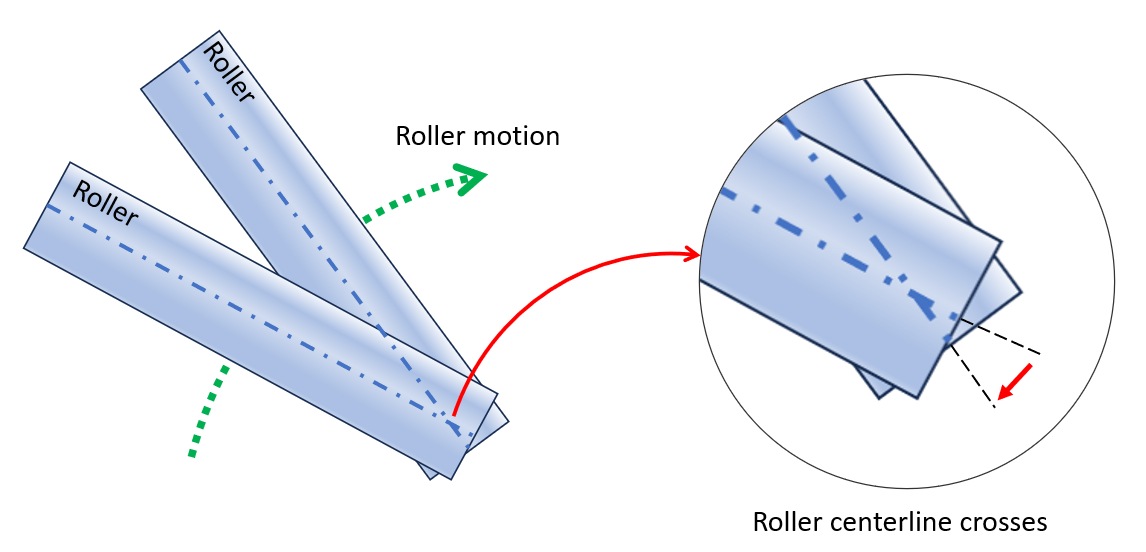
-
In the picture above, the tool center point moves ‘forward’ but the right side of the roller moves ‘backwards’ which results in a ‘twist’ motion. This macro sets the allowable distance that either side of the roller is allowed to move in the opposite direction of the center point of the roller. By default, the tolerance is set to 0. When a twist is detected, a warning similar to below is reported in the logger:
-
Warning: Roller motion twist detected. Initial tape projection failed at line: (2234) N4472 G1 X532.278 Y30.918 Z38.404 A-19.235 B4.349 C43.229 S1 R21.012 (0011111111000000)
Example —
-
Override Value = 0.005
-
Override Text = Not Used
RotaryAngleConversion
-
Function — ROTATION PLANE
-
Status — ACTIVE
-
Input —
- Text: FIRST n m SECOND n m SPINDLE n m
- Value: Not used
-
Comment — Added in V9.1
-
Input —
- Text: FIRST n m SECOND n m SPINDLE n m
- Value: Not used
This macro sets parameters that determines how rotary angles are to be converted. These parameters are then used when converting IJK to angles. The default is to do no conversion.
For the text argument, you can specify FIRST, SECOND, or SPINDLE, or any combination of these. FIRST and SECOND refers to the first and second angle. The following are examples of valid Text arguments:
-
OT= FIRST 1
-
OT= SECOND 3
-
OT= FIRST 1 SECOND 1 SPINDLE 5 45 Conversion Types:
-
0: No conversion
-
1: -180 to 179.99999
-
2: -179.9999 to 180
-
3: 0 to 359.999999
-
4: .000001 to 360
-
5 m: (m – 360) to m (if m was 330, then it would be from -30 to 329.9999)
-
6 m: (m – 360) to m (if m was 330, then it would be from -29.9999 to 330)
Example —
-
OT=FIRST 1 SECOND 3 Based on these parameters, any macro that uses these parameters would convert angles as follows:
-
First angle = 270 -90
-
First angle = 180 -180
-
First angle = 90 90
-
Second angle = -45 315 Note — “m” is any number in the range (0, 360).
RotaryAxisLinearRewind
-
Function — MOTION
-
Status — ACTIVE
-
Input —
- Text: Register of Rotary axis (A, B, C, A2, B2, C2, A3, B3, C3)
- Value: Not Used
Converts the current position of the specified rotary component (specified by register) to a value between 0-360. No motion takes place.
RotaryAxisLinearRewind360_360
-
Function — MOTION
-
Status — ACTIVE
-
Input —
- Text: Register of Rotary axis (A, B, C, A2, B2, C2, A3, B3,C3)
- Value: Not Used
-
Comment — Also see: RotaryLinearRewind360_360
-
Input —
- Text: Register of Rotary axis (A, B, C, A2, B2, C2, A3, B3,C3)
- Value: Not Used
Converts the current position of the specified rotary component (specified by register) to a value between -360 and 360. No motion takes place. This conversion will be conditional upon the current position being beyond the specified minimum value. For example: Assume that the B rotary is a Linear table, and current value is 450. RotaryAxisLinearRewind360-360 OT=B OV=720 → The B value would remain at 450. RotaryAxisLinearRewind360-360 OT=B OV=0 → The B value would change to 90. Now assume that the current value is -450. RotaryAxisLinearRewind360-360 OT=B OV=720 → The B value would remain at -450. RotaryAxisLinearRewind360-360 OT=B OV=0 → The B value would change to -90.
RotaryAxisLock
-
Function — ** MISCELLANEOUS
-
Status — ** ACTIVE
-
Input —
- Text: Name of the rotary component
- Value: 0 = unlock the rotary component
-
Comment — ** Added V7.1
-
Input —
- Text: Name of the rotary component
- Value:
- 0 = unlock the rotary component
- 1 = lock the rotary component
This macro is used to disable rotary axis component motion when resolving IJK to ABC conversions. This macro is applied when using the Ijk2AbcType macro type (99) Universal. The rotary axis motion is not disabled when using direct axis programming.
An Override Value of "1" locks the rotary component specified in the Override Text field. The locked component remains locked until it is reset by a call to this macro with an Override Value of "0".
An Override Value of "0" unlocks the rotary component specified in the Override Text field.
See Also — Ijk2AbcType
RotaryControlPointOnOff
-
Function — TOOL OFFSETS
-
Status — ACTIVE
-
Input —
- Text: Not Used
- Value: 0 = turns Off the RPCP and/or RTCP functions
-
Input —
- Text: Not Used
- Value:
- 0 = turns Off the RPCP and/or RTCP functions
- 1 = turns On the RPCP and/or RTCP functions
Sets the Rotary Tool Control Point ("RTCP") and/or Rotary Part Control Point ("RPCP"), as determined by the NC machine configuration. When called with a value of "1" the macro turns ON a combination of RTCP and RPCP for the machine being used. A value of "0" turns OFF the RPCP and/or RTCP functions.
RotaryDirCCW
-
Function — MOTION
-
Status — ACTIVE
-
Input —
- Text: Possible options are:
- Value: Not Used
This macro sets the direction for an EIA (360 Absolute) rotary table or a Turret to be always Counter Clockwise. By default, the affect applies to all rotary axes and Turrets. Individual rotary axes can be controlled via entering the axis name in the Override Text field, e.g.: "AAXIS", "BAXIS", etc.
RotaryDirCW
-
Function — MOTION
-
Status — ACTIVE
-
Input —
- Text: Possible options are:
- Value: Not Used
This macro sets the direction for an EIA (360 Absolute) rotary table or a Turret to be always Clockwise. By default, the affect applies to all rotary axes and Turrets. Individual rotary axes can be controlled via entering the axis name in the Override Text field, e.g.: "AAXIS", "BAXIS", etc.
RotaryDirLinear
-
Function — MOTION
-
Status — ACTIVE
-
Input —
- Text: Possible options are:
- Value: Not Used
This macro sets the direction for an EIA (360 Absolute) rotary table or a Turret to be linear. The value will be first converted into a number between 0 and 360, and then the rotation will act as if it is a linear table. By default, the affect applies to all rotary axes and Turrets. Individual rotary axes can be controlled via entering the axis name in the Override Text field, e.g.: "AAXIS", "BAXIS", etc.
RotaryDirLocalMachine
-
Function — MOTION
-
Status — ACTIVE
-
Input —
- Text: Not used
- Value: 0 = Off (local coordinates will be used)
-
Comment — Added in V9.1
-
Input —
- Text: Not used
- Value:
- 0 = Off (local coordinates will be used)
- 1 = On (machine coordinates will be used)
This macro sets the type of coordinates used to determine the direction of rotation, for an EIA (360 Absolute) rotary table or a Turret, when the distance is 180 degrees. This macro only applies when there is an offset and the move is exactly 180 degrees. When value is 0, the rotary moves in the direction based on the local coordinates and the corresponding “Shortest Distance” type. When value is 1, the offset is added to the starting and ending angles and then the angles are converted into an angle between 0-360. The new direction is based on the corresponding “Shortest Distance” type.
Example -
RotaryDirShortestDist3 is set and there is a 90 degree offset
Off (local)
 0 to 180 → CW
 30 to 210 → CW
 210 to 30 → CCW
-180 to 0 → CW
- 90 to 90 (270 to 90) → CCW
On (machine)
0 to 180 → CW
30 to 210 → CW
210 to 30 → CCW
180 to 0 → CWW
90 to 90 (270 to 90) → CW
Note - By default, the rotation direction applies to all rotary axes and Turrets.
See Also — RotaryDirShortestDist2, RotaryDirShortestDist3, RotaryDirShortestDist4, and RotaryDirShortestDistLinear
RotaryDirPosCCW
-
Function — MOTION
-
Status — ACTIVE
-
Input —
- Text: Possible options are:
- Value: Not Used
This macro sets the direction for an EIA (360 Absolute) rotary table or a Turret to be counterclockwise when the angle is positive and clockwise when the angle is negative. By default, the affect applies to all rotary axes and Turrets. Individual rotary axes can be controlled via entering the axis name in the Override Text field, e.g.: "AAXIS", "BAXIS", etc.
RotaryDirPosCCWAbsolute
-
Function — MOTION
-
Status — ACTIVE
-
Input —
- Text: Possible options are:
- Value: Not Used
-
Comment — Added V6.2
-
Input —
- Text: Possible options are:
- Value: Not Used
This macro sets the direction for an EIA (360 Absolute) rotary table or a Turret to be counterclockwise whenthe angle is positive and clockwise when the angle is negative. Unlike RotaryDirPosCCW, a minus sign is used to determine the direction and the angle (-90 = 270). By default, the affect applies to all rotary axes and Turrets. Individual rotary axes can be controlled via entering the axis name in the Override Text field, e.g.: "AAXIS", "BAXIS", etc.
RotaryDirPosCW
-
Function — MOTION
-
Status — ACTIVE
-
Input —
- Text: Possible options are:
- Value: Not Used
Similar to RotaryDirPosCCW, but rotary directions are reversed. This macro sets the direction for an EIA (360 Absolute) rotary table or a Turret to be clockwise when the angle is positive and counterclockwise when the angle is negative. By default, the affect applies to all rotary axes and Turrets. Individual rotary axes can be controlled via entering the axis name in the Override Text field, e.g.: "AAXIS", "BAXIS", etc.
RotaryDirPosCWAbsolute
-
Function — MOTION
-
Status — ACTIVE
-
Input —
- Text: Possible options are:
- Value: Not Used
-
Comment — Added V6.2
-
Input —
- Text: Possible options are:
- Value: Not Used
Similar to RotaryDirPosCCWAbsolute, but rotary directions are reversed. This macro sets the direction for an EIA (360 Absolute) rotary table or a Turret to be clockwise when the angle is positive and counterclockwise when the angle is negative. Unlike RotaryDirPosCW, a minus sign is used to determine the direction and the angle (-90 = 270). By default, the affect applies to all rotary axes and Turrets. Individual rotary axes can be controlled via entering the axis name in the Override Text field, e.g.: "AAXIS", "BAXIS", etc.
RotaryDirShortestDist
-
Function — MOTION
-
Status — ACTIVE
-
Input —
- Text: Possible options are:
- Value: Not Used
This macro sets the direction of rotation, for an EIA (360 Absolute) rotary table or a Turret, so that the table rotates the shortest distance get from the current position to the final position. Vericut uses the rotation value and its sign to specify the absolute rotary position. The rotary moves in the direction that is shortest. If the move is exactly 180 degrees, both directions are equally short. The direction of the move is undefined. Vericut will therefore pick a direction, and output the following Warning message: “Warning: The direction to move is undefined (180 degree move set to Shortest Distance)”. If you do not want the warning message, you must pick one of the other “Shortest Distance” types which defines the direction to take in the case of a 180 degree move. By default, the rotation direction applies to all rotary axes and Turrets. Individual rotary axes can be controlled via entering the axis name in the Override Text field, e.g.: "AAXIS", "BAXIS", etc.
See Also — RotaryDirShortestDist180CCW, RotaryDirShortestDist180CW, RotaryDirShortestDist2 and RotaryDirShortestDist3
RotaryDirShortestDist180CCW
-
Function — MOTION
-
Status — ACTIVE
-
Input —
- Text: Possible options are:
- Value: Not Used
-
Comment — Added V6.2
-
Input —
- Text: Possible options are:
- Value: Not Used
This macro sets the direction for an EIA (360 Absolute) rotary table or a Turret to be the direction which is the shortest distance from the current position to the final position. Vericut uses the rotation value and its sign to determine the absolute rotary position. The rotary moves in the direction that is shortest. If the move is exactly 180 degrees, it will always move in a counter-clockwise direction. By default, the rotation direction applies to all rotary axes and Turrets. Individual rotary axes can be controlled via entering the axis name in the Override Text field, e.g.: "AAXIS", "BAXIS", etc.
See Also — RotaryDirShortestDist, RotaryDirShortestDist2, RotaryDirShortestDist3 and RotaryDirShortestDist180CW
RotaryDirShortestDist180CW
-
Function — MOTION
-
Status — ACTIVE
-
Input —
- Text: Possible options are:
- Value: Not Used
-
Comment — Added V6.2
-
Input —
- Text: Possible options are:
- Value: Not Used
This macro sets the direction for an EIA (360 Absolute) rotary table or a Turret to be the direction which is the shortest distance from the current position to the final position. Vericut uses the rotation value and its sign to determine the absolute rotary position. The rotary moves in the direction that is shortest. If the move is exactly 180 degrees, it will always move in a clockwise direction. By default, the rotation direction applies to all rotary axes and Turrets. Individual rotary axes can be controlled via entering the axis name in the Override Text field, e.g.: "AAXIS", "BAXIS", etc.
See Also — RotaryDirShortestDist, RotaryDirShortestDist2, RotaryDirShortestDist3 and RotaryDirShortestDist180CCW
RotaryDirShortestDist2
-
Function — MOTION
-
Status — ACTIVE
-
Input —
- Text: Possible options are:
- Value: Not Used
-
Comment — Added V7.3
-
Input —
- Text: Possible options are:
- Value: Not Used
This macro sets the direction for an EIA (360 Absolute) rotary table or a Turret to be the direction which is the shortest distance from the current position to the final position. Vericut uses the rotation value and its sign to specify the absolute rotary position. The rotary moves in the direction that is shortest. If the move is exactly 180 degrees, then the starting and ending angles are converted into an angle between 0-360. If you are moving to a larger angle, the rotary will move clockwise. If you are moving to a smaller angle, the rotary will move counter-clockwise. The only exception is when moving from 180 degrees to 0 degrees, the rotary will move in a clockwise direction.
For example:
-
0 to 180 → CW
-
30 to 210 → CW
-
210 to 30 → CCW
-
180 to 0 → CW
-
90 to 90 (270 to 90) → CCW
-
By default, the rotation direction applies to all rotary axes and Turrets. Individual rotary axes can be controlled via entering the axis name in the Override Text field, e.g.: "AAXIS", "BAXIS", etc.
See Also — RotaryDirShortestDist, RotaryDirShortestDist180CCW, RotaryDirShortestDist180CW and RotaryDirShortestDist3
RotaryDirShortestDist3
-
Function — MOTION
-
Status — ACTIVE
-
Input —
- Text: Possible options are:
- Value: Not Used
-
Comment — Added V7.3.3
-
Input —
- Text: Possible options are:
- Value: Not Used
This macro sets the direction of rotation, for an EIA (360 Absolute) rotary table or a Turret, so that the table rotates the shortest distance get from the current position to the final position. The rotary moves in the direction that is shortest. If the move is exactly 180 degrees, the starting and ending angles will be converted converted into an angle between 0-360 degrees. Then if you are moving to a larger angle, the rotary will move clockwise. If you are moving to a smaller angle, the rotary will move counter-clockwise.
For example:
-
0 to 180 → CW
-
30 to 210 → CW
-
210 to 30 → CCW
-
180 to 0 → CCW
-
90 to 90 (270 to 90) → CCW
-
By default, the rotation direction applies to all rotary axes and Turrets. Individual rotary axes can be controlled via entering the axis name in the Override Text field, e.g.: AAXIS", "BAXIS", etc.
See Also — RotaryDirShortestDist, RotaryDirShortestDist180CCW, and RotaryDirShortestDist180CW.
RotaryDirShortestDist4
-
Function — MOTION
-
Status — ACTIVE
-
Input —
- Text: Possible options are:
- Value: Not Used
-
Comment — Added V8.1
-
Input —
- Text: Possible options are:
- Value: Not Used
This macro sets the direction for an EIA (360 Absolute) rotary table or a Turret to be the direction which is the shortest distance from the current position to the final position. Vericut uses the rotation value and its sign to specify the absolute rotary position. The rotary moves in the direction that is shortest. If the move is exactly 180 degrees, then the starting and ending angles are converted into an angle between 0-360. If you are moving to a larger angle, the rotary will move clockwise. If you are moving to a smaller angle, the rotary will move counter-clockwise. The two exceptions are when moving from 180 degrees to 0 degrees, the rotary will move in a clockwise direction, and when moving from 0 to 180 degrees, the rotary will move in a counter clockwise direction.
For example:
-
0 to 180 → CW
-
30 to 210 → CW
-
210 to 30 → CCW
-
180 to 0 → CCW
-
90 to 90 (270 to 90) → CCW
-
By default, the rotation direction applies to all rotary axes and Turrets. Individual rotary axes can be controlled via entering the axis name in the Override Text field, e.g.: "AAXIS", "BAXIS", etc.
See Also — RotaryDirShortestDist, RotaryDirShortestDist180CCW, RotaryDirShortestDist180CW, and RotaryDirShortestDist3.
RotaryDirShortestDist5
-
Function — MOTION
-
Status — ACTIVE
-
Input —
- Text: Possible options are:
- Value: Not Used
-
Comment — Added V8.1
-
Input —
- Text: Possible options are:
- Value: Not Used
This macro sets the direction for an EIA (360 Absolute) rotary table or a Turret to be the direction which is the shortest distance from the current position to the final position. Vericut uses the rotation value and its sign to specify the absolute rotary position. The rotary moves in the direction that is shortest. If the move is exactly 180 degrees, then convert the starting and ending angles into a value within the interval I = [-180,179.99999]. If the angle the rotary is moving to is larger than its starting angle position, then the Rotary will move clockwise. If the angle the rotary is moving to is smaller than its starting angle position, then the Rotary will move counter clockwise.
For example:
-
0 to 180 → (0 to -180) → CCW
-
30 to 210 → (30 to -150) → CCW
-
210 to 30 → (-150 to 30) → CW
-
180 to 0 → (-180 to 0) → CW
-
90 to 90 → (-90 to 90) → CW
-
By default, the rotation direction applies to all rotary axes and Turrets. Individual rotary axes can be controlled via entering the axis name in the Override Text field, e.g.: "AAXIS", "BAXIS", etc.
See also — RotaryDirShortestDist, RotaryDirShortestDist180CCW, RotaryDirShortestDist180CW, RotaryDirShortestDist3, and RotaryDirShortestDist4.
RotaryDirShortestDist6
-
Function — MOTION
-
Status — ACTIVE
-
Input —
- Text: None
- Value: Not Used
-
Comment — Added V8.1
-
Input —
- Text:
- Value: Not Used
This macro sets the direction for an EIA (360 Absolute) rotary table or a Turret to be the direction which is the shortest distance from the current position to the final position. Vericut uses the rotation value and its sign to specify the absolute rotary position. The rotary moves in the direction that is shortest. If the move is exactly 180 degrees, then convert the starting and ending angles into a value within the interval I = [-179.99999,180]. If the angle the rotary is moving to is larger than its starting angle position, then the Rotary will move clockwise. If the angle the rotary is moving to is smaller than its starting angle position, then the Rotary will move counter clockwise.
For example:
-
0 to 180 → (0 to 180) → CW
-
30 to 210 → (30 to -150) → CCW
-
210 to 30 → (-150 to 30) → CW
-
180 to 0 → (180 to 0) → CCW
-
90 to 90 → (-90 to 90) → CW
-
By default, the rotation direction applies to all rotary axes and Turrets. Individual rotary axes can be controlled via entering the axis name in the Override Text field, e.g.: "AAXIS", "BAXIS", etc.
See Also — RotaryDirShortestDist, RotaryDirShortestDist180CCW, RotaryDirShortestDist180CW, RotaryDirShortestDist3, RotaryDirShortestDist4, and RotaryDirShortestDist5.
RotaryDirShortestDistLinear
-
Function — MOTION
-
Status — ACTIVE
-
Input —
- Text: Possible options are:
- Value: Not Used
-
Comment — Added V8.0
-
Input —
- Text: Possible options are:
- Value: Not Used
This macro sets the direction for an EIA (360 Absolute) rotary table or a Turret to be the direction which is the shortest distance from the current position. If the move is exactly 180 degrees, then the starting angle is converted into an angle between 0-360. If the new angle is bigger, it moves 180 CW(CW as seen look down the motion axis, assuming the rotary is on the part side), and if the new angle is smaller, it moves 180 CCW.
Note — After the first angle is converted, it moves in the direction that it would move if this was a “Linear” table. By default, the affect applies to all rotary axes and Turrets. Individual rotary axes can be controlled via entering the axis name in the Override Text field, e.g.: "AAXIS", "BAXIS", etc.
RotaryFeedFactor
-
Function — FEEDS and SPEEDS
-
Status — ACTIVE
-
Input —
- Text: Not Used
- Value: Multiplier
-
Comment — Added V7.0.2
-
Input —
- Text: Not Used
- Value: Multiplier
This macro is used to set the multiplier used by FeedPerMinuteType macro case 5. The multiplier sets the mm-degree ratio. The default ratio is 1. The multiplier is set in mm-per-degree units. For example, if a rotary delta is 90 degrees, and the multiplier is (500/360) mm/degree, and the current linear unit is INCH, then the corresponding "linear" delta for this rotary is 90*(500/360)/25.4 inches.
RotaryFeedRate
-
Function — FEEDS and SPEEDS
-
Status — ACTIVE
-
Input —
- Text: Not Used
- Value: Feedrate
-
Comment — Added V6.2
-
Input —
- Text: Not Used
- Value: Feedrate
The rotary feedrate will be set to the specified value. This value is only used to calculate the time for a motion when in FeedPerMinute mode, and the FeedPerMinuteType is set to 4.
RotaryLinearRewind
-
Function — MOTION
-
Status — ACTIVE
-
Input —
- Text: Not Used
- Value: Not Used
Converts the current position of all rotary components to a value between 0-360. No motion takes place. Since this macro updates all rotaries, you should be certain that this is what you really want. Use RotaryAxisLinearRewind to apply the same conversion for a specified Axis.
RotaryLinearRewind360_360
-
Function — MOTION
-
Status — ACTIVE
-
Input —
- Text: Not Used
- Value: Minimum angle/position
Converts the current position of all rotary components to a value between -360 and 360. No motion takes place. This conversion will be conditional upon the current position being beyond the specified minimum value. Since this macro updates all rotaries, you should be certain that this is what you really want. Use RotaryAxisLinearRewind360-360 to apply the same conversion for a specified Axis. For example: Assume that the B is 450 and C is at -450 RotaryAxisLinearRewind360-360 OV=720 → The B and C values remain unchanged. RotaryAxisLinearRewind360-360 OV=0 → The B changes to 90 and C changes to -90
RotaryTypeAbsolute
-
Function — MOTION
-
Status — ACTIVE
-
Input —
- Text: Possible options are:
- Value: Not Used
This macro changes the Rotary Type to Absolute for the specified axis. The axis is specified by entering the axis name in the Override Text field, e.g.: "AAXIS", "BAXIS", "CAXIS", "A2AXIS", "B2AXIS", "C2AXIS". No other action is taken. The type of Absolute table will be based on previous settings.
Note — S: 1. When in absolute mode, the input angle will be converted to an angle between 0-360 when the corresponding AxisMotion (AAxisMotion, BAxisMotion), etc.) command is executed. 2. RotaryTypeAbsolute only sets the rotary table type, and is NOT related to the series of macros which set the direction for an Absolute table (RotaryDirCCW, RotaryDirCW, RotaryDirLinear, RotaryDirPosCCW, RotaryDirPosCW, RotaryDirShortestDist).
RotaryTypeLinear
-
Function — MOTION
-
Status — ACTIVE
-
Input —
- Text: Possible options are:
- Value: Not Used
This macro changes the Rotary Type to Linear for the specified axis and converts the rotary angle from an EIA Absolute type to a Linear type. The type of conversion is set in the macro RotaryTypeLinearOption. The axis is specified by entering the axis name in the Override Text field, e.g.: "AAXIS", "BAXIS", "CAXIS", "A2AXIS", "B2AXIS", "C2AXIS".
Note — RotaryTypeLinear only sets the rotary table type, and is NOT related to the series of macros which set the direction for an Absolute table (RotaryDirCCW, RotaryDirCW, RotaryDirLinear, RotaryDirPosCCW, RotaryDirPosCW, RotaryDirShortestDist).
RotaryTypeLinearOption
-
Function — MOTION
-
Status — ACTIVE
-
Input —
- Text: Not Used
- Value: Possible options are:
-
Comment — Added V8.0
-
Input —
- Text: Not Used
- Value:
- 1 - Convert angle to: -180 to 180 degrees.
- 2 - Convert angle to: 0 to 360 degrees.
- 3 - Convert angle to: -360 to 360 degrees (no conversion).
This macro sets the type of conversion that will take place when converting the rotary angle from an EIA Absolute table to a Linear table. This conversion takes place in the RotaryTypeLinear macro.
RotateCancel
-
Function — ROTATE 2D
-
Status — ACTIVE
-
Input —
- Text: Not Used
- Value: Not Used
Cancels the current rotation.
RotateMacro
-
Function — ROTATE 2D
-
Status — SPECIAL
-
Input —
- Text: Not Used
- Value: Not Used
Fanuc specific 2D rotation that causes the coordinate system to be rotated, within the active plane, by a specified angle. The angle is specified with the RotationAngle macro. The center of rotation can be specified with calls to the RotateXValue, RotateYValue, and RotateZValue macros. The XYZ values are based on the current coordinate system. The rotation angle is based on the machine coordinate system.
If the first motion block following the call to RotateMacro is in Incremental mode, the center of rotation will be ignored.
Example —
G90X0Y0 ==> X0 Y0
G68X1Y1R45
X0Y0 ==> X1 Y-.4142 The G68 cause the origin to be shifted
X1 ==> X1.707 Y.2929
Y1 ==> X1, Y1
X0 ==> X.2929, Y.2929
Y0 ==> X1 Y-.4142
G91G68X1Y1R45 ==> Because of the G91, rotate angle is now 90. Center is independent of G90/G91 mode for this block.
G90X0Y0 ==> X2 Y0
X1 ==> X2 Y1
Y1 ==> X1 Y1
X0 ==> X1 Y0
Y0 ==> X2 Y0
RotateOrigin
-
Function — ROTATE 2D
-
Status — SPECIAL
-
Input —
- Text: Not Used
- Value: Not Used
2D rotation that causes the coordinate system to be rotated within the active plane by a specified angle. The angle is specified with the RotationAngle macro. The center of rotation is always the current origin. The rotation angle is based on the machine coordinate system.
Example —
G90X0Y0 ==> X0 Y0
G68X1Y1R45
X0Y0 ==> X0 Y0
X1 ==> X.707 Y.707
Y1 ==> X1, Y1.414
X0 ==> X-.707, Y.707
Y0 ==> X0 Y0
G91G68X1Y1R45 ==> Because of the G91, rotate angle is now 90.
G90X0Y0 ==> X0 Y0
X1 ==> X0 Y1
Y1 ==> X-1 Y1
X0 ==> X-1 Y0
Y0 ==> X0 Y0
RotateXValue
-
Function — ROTATE 2D
-
Status — ACTIVE
-
Input —
- Text: Not Used
- Value: X coordinate value of the point of rotation
Sets the X coordinate value of the point of rotation.
RotateXYZ
-
Function — ROTATE 2D
-
Status — ACTIVE
-
Input —
- Text: Not Used
- Value: Not Used
2D rotation that causes the coordinate system to be rotated, within the active plane, by a specified angle. The angle is specified with the RotationAngle macro. The center of rotation can be specified with calls to the RotateXValue, RotateYValue, and RotateZValue macros. The XYZ values are based on the current coordinate system. The rotation angle is based on the machine coordinate system. This macro is identical to the Fanuc specific RotateMacro except is independent of the mode of the block following the G68 command. See RotateMacro for a G-Code example.
RotateYValue
-
Function — ROTATE 2D
-
Status — ACTIVE
-
Input —
- Text: Not Used
- Value: Y coordinate value of the point of rotation
RotateZValue
-
Function — ROTATE 2D
-
Status — ACTIVE
-
Input —
- Text: Not Used
- Value: Z coordinate value of the point of rotation
Sets the Z coordinate value of the point of rotation.
RotationAbsAngle
-
Function — ROTATE 2D
-
Status — ACTIVE
-
Input —
- Text: Not Used
- Value: Rotation angle
Sets the total rotation angle to be the specified value.
RotationAngle
-
Function — ROTATE 2D
-
Status — ACTIVE
-
Input —
- Text: Not Used
- Value: Rotation angle
Specifies the angle to be used with the 2D rotation macros (RotateMacro, RotateXYZ, RotateOrigin and OkumaShiftRotate). The angle will be interpreted as absolute, or incremental, depending on the current mode (G90/G91). This macro will also adjust for mirroring.
See Also — RotationAbsAngle and RotationIncAngle
RotationIncAngle
-
Function — ROTATE 2D
-
Status — ACTIVE
-
Input —
- Text: Not Used
- Value: Incremental rotation angle
Increments the total rotation angle by the specified value.
RotationPlane
-
Function — ROTATION PLANE
-
Status — ALTERNATE
-
Input —
- Text: ONE, TWO, THREE, FOUR (default), FIVE, SIX or SEVEN
- Value: Not Used
-
Comment — Use RotationPlane2
-
Input —
- Text: ONE, TWO, THREE, FOUR (default), FIVE, SIX or SEVEN
- Value: Not Used
Turns on the rotation plane using the values specified via the RotationPlaneXPoint, RotationPlaneYPoint, RotationPlaneZPoint, RotationPlaneAngle1, RotationPlaneAngle2, and RotationPlaneAngle3 macros. (Don't re-calculate the current position into the new coordinate system.) The rotation plane remains active until replaced by a new rotated plane, or canceled via RotationPlaneCancel. The Text argument specifies the rotation plane. This includes defining which input parameters to use, and which rotation plane matrix is created. Parameters associated with rotation planes are specific to an individual rotation plane. If this field is not present, it defaults to FOUR.
RotationPlane2
-
Function — ROTATION PLANE
-
Status — ACTIVE
-
Input —
- Text: ONE, TWO, THREE, FOUR (default), FIVE, SIX or SEVEN
- Value: Not Used
Turns on the rotation plane using the values specified via the RotationPlaneXPoint, RotationPlaneYPoint and RotationPlaneZPoint macros and RotationPlaneAngle1, RotationPlaneAngle2, RotationPlaneAngle3 macros. The local coordinates are then re-calculated based on the new coordinate system. The Text argument specifies the rotation plane. This includes defining which input parameters to use, and which rotation plane matrix is created. Parameters associated with rotation planes are specific to an individual rotation plane. If this field is not present, it defaults to FOUR.
RotationPlane2D
-
Function — ROTATION PLANE
-
Status — ACTIVE
-
Input —
- Text: ONE, TWO, THREE, FOUR (default), FIVE, SIX or SEVEN.
- Value: Degrees to rotate.
-
Comment — Added in V8.2
-
Input —
- Text: ONE, TWO, THREE, FOUR (default), FIVE, SIX or SEVEN.
- Value: Degrees to rotate.
Creates a rotation plane by rotating by the specified value within the current motion plane. An offset can also be specified by previously calling the RotationPlaneXPoint, RotationPlaneYPoint and RotationPlaneZPoint. The local coordinates are then re-calculated based on the new coordinate system. The Text argument specifies the rotation plane. This includes defining which input parameters to use, and which rotation plane matrix is created. Parameters associated with rotation planes are specific to an individual rotation plane. If this field is not present, it defaults to FOUR.
RotationPlaneAngle1
-
Function — ROTATION PLANE
-
Status — ACTIVE
-
Input —
- Text: Axis to rotate about (X,Y,Z) followed by optional Rotation Plane Identifier
- Value: Rotation angle
Macros RotationPlaneAngle1-3 define the first, second, third angles to be applied, respectively. An Override Text value of "X", "Y", or "Z" defines the axis about which to apply the rotation. The Rotation Plane Identifier specifies which Rotation Plane this applies to. If not specified, Rotation Plane 4 will be used This macro is only setting the parameter. After setting all parameters, use RotationPlane2 (or similar macro) to update the Rotation Plane.
RotationPlaneAngle2
-
Function — ROTATION PLANE
-
Status — ACTIVE
-
Input —
- Text: Axis to rotate about (X,Y,Z) followed by optional Rotation Plane Identifier
- Value: Rotation angle
Macros RotationPlaneAngle1-3 define the first, second, third angles to be applied, respectively. An Override Text value of "X", "Y", or "Z" defines the axis about which to apply the rotation. The Rotation Plane Identifier specifies which Rotation Plane this applies to. If not specified, Rotation Plane 4 will be used This macro is only setting the parameter. After setting all parameters, use RotationPlane2 (or similar macro) to update the Rotation Plane.
RotationPlaneAngle3
-
Function — ROTATION PLANE
-
Status — ACTIVE
-
Input —
- Text: Axis to rotate about (X,Y,Z) followed by optional Rotation Plane Identifier
- Value: Rotation angle
Macros RotationPlaneAngle1-3 define the first, second, third angles to be applied, respectively. An Override Text value of "X", "Y", or "Z" defines the axis about which to apply the rotation. The Rotation Plane Identifier specifies which Rotation Plane this applies to. If not specified, Rotation Plane 4 will be used This macro is only setting the parameter. After setting all parameters, use RotationPlane2 (or similar macro) to update the Rotation Plane.
RotationPlaneCancel
-
Function — ROTATION PLANE
-
Status — ALTERNATE
-
Input —
- Text: ONE, TWO, THREE, FOUR (default), FIVE, SIX or SEVEN
- Value: Not Used
-
Comment — Use RotationPlaneCancelReset
-
Input —
- Text: ONE, TWO, THREE, FOUR (default), FIVE, SIX or SEVEN
- Value: Not Used
Cancels the specified rotation plane. The Text argument is optional, and defaults to FOUR if not specified.
RotationPlaneCancel2
-
Function — ROTATION PLANE
-
Status — ALTERNATE
-
Input —
- Text: ONE, TWO, THREE, FOUR (default), FIVE, SIX or SEVEN
- Value: Not Used
-
Comment — Use RotationPlaneCancelReset
-
Input —
- Text: ONE, TWO, THREE, FOUR (default), FIVE, SIX or SEVEN
- Value: Not Used
This macro cancels the specified rotation plane, and converts the current local axis position into the new coordinate system. The Text argument is optional, and defaults to FOUR if not specified.
RotationPlaneCancelReset
-
Function — ROTATION PLANE
-
Status — ACTIVE
-
Input —
- Text: ONE, TWO, THREE, FOUR (default), FIVE, SIX, SEVEN or ALL
- Value: Not Used
-
Comment — Added V6.0
-
Input —
- Text: ONE, TWO, THREE, FOUR (default), FIVE, SIX, SEVEN or ALL
- Value: Not Used
This macro cancels and resets the specified rotation plane, and converts the current local axis position into the new coordinate system. The Text argument is optional, and defaults to FOUR if not specified. If “ALL” is specified, it will cancel and reset all rotation planes.
RotationPlaneEnable2
-
Function — ROTATION PLANE
-
Status — ACTIVE
-
Input —
- Text: ONE, TWO, THREE, FOUR (default), FIVE, SIX or SEVEN
- Value: Not Used
-
Comment — Added V6.0
-
Input —
- Text: ONE, TWO, THREE, FOUR (default), FIVE, SIX or SEVEN
- Value: Not Used
This macro restores the specified rotation plane, and converts the current local axis position into the new coordinate system.
Note — This macro does not re-calculate the matrix. If RotationPlaneCancel2 is used to turn off the rotation plane, then this macro can be used to get you back to where you were. The Text argument is optional, and defaults to FOUR if not specified.
RotationPlaneInc2D
-
Function — ROTATION PLANE
-
Status — ACTIVE
-
Input —
- Text: ONE, TWO, THREE, FOUR (default), FIVE, SIX, or SEVEN
- Value: degrees to rotate (incremental)
-
Comment — Added in V9.0
-
Input —
- Text: ONE, TWO, THREE, FOUR (default), FIVE, SIX, or SEVEN
- Value: degrees to rotate (incremental)
Creates a rotation plane by rotating by the specified value within the current motion plane. The input value is incremental. It is expected that the motion plane has not changed since previously calling RotationPlane2D or RotationPlaneInc2D. This macro is identical to RotationPlane2D except that the input value is incremental. An offset can also be specified by previously calling the RotationPlaneXPoint, RotationPlaneYPoint, and RotationPlaneZPoint. The local coordinates are then re-calculated based on the new coordinate system. The Text argument specifies the rotation plane. This includes defining which input parameters to use, and which rotation plane matrix is created. Parameters associated with rotation planes are specific to an individual rotation plane. If this field is not present, it defaults to FOUR.
RotationPlaneIncAngle1
-
Function — ROTATION PLANE
-
Status — ACTIVE
-
Input —
- Text: Axis to rotate about (X,Y,Z) followed by optional Rotation Plane Identifier
- Value: Incremental rotation angle
This macro updates the Rotation Plane first angle parameter by the specified incremental amount. See also: RotationPlaneAngle1. Although the intent of this macro is to update the angle, if the rotation axis (X,Y,Z) is different, this parameter will also be updated. The Rotation Plane Identifier specifies which Rotation Plane this applies to. If not specified, Rotation Plane 4 will be used This macro is only setting the parameter. After setting all parameters, use RotationPlane2 (or similar macro) to update the Rotation Plane.
RotationPlaneIncAngle2
-
Function — ROTATION PLANE
-
Status — ACTIVE
-
Input —
- Text: Axis to rotate about (X,Y,Z) followed by optional Rotation Plane Identifier
- Value: Incremental rotation angle
This macro updates the Rotation Plane second angle parameter by the specified incremental amount. See also: RotationPlaneAngle2. Although the intent of this macro is to update the angle, if the rotation axis (X,Y,Z) is different, this parameter will also be updated. The Rotation Plane Identifier specifies which Rotation Plane this applies to. If not specified, Rotation Plane 4 will be used This macro is only setting the parameter. After setting all parameters, use RotationPlane2 (or similar macro) to update the Rotation Plane.
RotationPlaneIncAngle3
-
Function — ROTATION PLANE
-
Status — ACTIVE
-
Input —
- Text: Axis to rotate about (X,Y,Z) followed by optional Rotation Plane Identifier
- Value: Incremental rotation angle
This macro updates the Rotation Plane third angle parameter by the specified incremental amount. See also: RotationPlaneAngle3. Although the intent of this macro is to update the angle, if the rotation axis (X,Y,Z) is different, this parameter will also be updated. The Rotation Plane Identifier specifies which Rotation Plane this applies to. If not specified, Rotation Plane 4 will be used This macro is only setting the parameter. After setting all parameters, use RotationPlane2 (or similar macro) to update the Rotation Plane.
RotationPlaneIncXPoint
-
Function — ROTATION PLANE
-
Status — ACTIVE
-
Input —
- Text: ONE, TWO, THREE, FOUR, FIVE, SIX or SEVEN (optional)
- Value: Offset value
This macro updates the Rotation Plane X offset parameter by the specified incremental amount. See also: RotationPlaneXPoint. The Text argument specifies which Rotation Plane this applies to. If not specified, Rotation Plane 4 will be used. This macro is only setting the parameter. After setting all parameters, use RotationPlane2 (or similar macro) to update the Rotation Plane.
RotationPlaneIncYPoint
-
Function — ROTATION PLANE
-
Status — ACTIVE
-
Input —
- Text: ONE, TWO, THREE, FOUR, FIVE, SIX or SEVEN (optional)
- Value: Offset value
This macro updates the Rotation Plane Y offset parameter by the specified incremental amount. See also: RotationPlaneYPoint. The Text argument specifies which Rotation Plane this applies to. If not specified, Rotation Plane 4 will be used. This macro is only setting the parameter. After setting all parameters, use RotationPlane2 (or similar macro) to update the Rotation Plane.
RotationPlaneIncZPoint
-
Function — ROTATION PLANE
-
Status — ACTIVE
-
Input —
- Text: ONE, TWO, THREE, FOUR, FIVE, SIX or SEVEN (optional)
- Value: Offset value
This macro updates the Rotation Plane Z offset parameter by the specified incremental amount. See also: RotationPlaneZPoint. The Text argument specifies which Rotation Plane this applies to. If not specified, Rotation Plane 4 will be used. This macro is only setting the parameter. After setting all parameters, use RotationPlane2 (or similar macro) to update the Rotation Plane.
RotationPlaneInput
-
Function — ROTATION PLANE
-
Status — ACTIVE
-
Input —
- Text: Not used
- Value: 1 = Rotation Plane Angles (default), 2 = X and Y axes, 3 = X and Z axes, 4 = Angles about rotated axis
-
Comment — Added in V8.2
-
Input —
- Text: Not used
- Value: 1 = Rotation Plane Angles (default), 2 = X and Y axes, 3 = X and Z axes, 4 = Angles about rotated axis
This macro specifies the type of input that is being passed to the Rotation Plane logic. For Rotation Plane Angles, see the RotationPlaneAngle macros. For X,Y, Z axis, see the PlaneAxisVector macros.
Note — Using option 1 and specifying the angles in reverse order is the same as option 4.
RotationPlaneLocal
-
Function — ROTATION PLANE
-
Status — ALTERNATE
-
Input —
- Text: ONE, TWO, THREE, FOUR (default), FIVE, SIX or SEVEN
- Value: Not Used
-
Comment — Use RotationPlaneLocal2
-
Input —
- Text: ONE, TWO, THREE, FOUR (default), FIVE, SIX or SEVEN
- Value: Not Used
Adjusts how the specified rotation plane values are interpreted (ref. RotationPlaneAngle1). When called, rotation plane values are interpreted as incremental rotations and translations within the current rotation plane. The Text argument specifies the rotation plane. This includes defining which input parameters to use, and which rotation plane matrix is created. Parameters associated with rotation planes are specific to an individual rotation plane. If this field is not present, it defaults to FOUR
RotationPlaneLocal2
-
Function — ROTATION PLANE
-
Status — ACTIVE
-
Input —
- Text: ONE, TWO, THREE, FOUR (default), FIVE, SIX or SEVEN
- Value: Not Used
Similar to RotationPlaneLocal, but they differ in how they calculate the initial motion after setting the rotation plane, particularly in the case where all axes are not programmed. RotationPlaneLocal2 re-calculates the current position into the new coordinate system, where RotationPlaneLocal does not. The Text argument specifies the rotation plane. This includes defining which input parameters to use, and which rotation plane matrix is created. Parameters associated with rotation planes are specific to an individual rotation plane. If this field is not present, it defaults to FOUR
RotationPlaneMirrorIndex
-
Function — ROTATION PLANE
-
Status — ACTIVE
-
Input —
- Text: Not used
- Value: Specifies the Mirroring Rotation Plane. 1-7 (default is 1)
-
Comment — Added in V8.2
-
Input —
- Text: Not used
- Value: Specifies the Mirroring Rotation Plane. 1-7 (default is 1)
This macro specifies which rotation plane is being used for Mirroring. This information is used by the Working Plane and Ijk2Angles logic.
See also — Ijk2AnglesApplyMirroring and WPApplyMirroring.
RotationPlaneRestoreAxis
-
Function — ROTATION PLANE
-
Status — NOT RECOMMENDED
-
Input —
- Text: ONE, TWO, THREE, FOUR (default), FIVE, SIX or SEVEN
- Value: Not Used
-
Comment — Use macros RotationPlane2, RotationPlaneCancel2, RotationPlaneEnable2, RotationPlaneLocal2.
-
Input —
- Text: ONE, TWO, THREE, FOUR (default), FIVE, SIX or SEVEN
- Value: Not Used
Converts the previously specified axis into a non-rotated plane coordinate system. This macro should be called prior to canceling a rotation plane via RotationPlaneCancel. This macro should no longer be used.
RotationPlaneScale2
-
Function — ROTATION PLANE
-
Status — ACTIVE
-
Input —
- Text: ONE, TWO, THREE, FOUR (default), FIVE, SIX or SEVEN
- Value: Not Used
-
Comment — Added V7.4.2
-
Input —
- Text: ONE, TWO, THREE, FOUR (default), FIVE, SIX or SEVEN
- Value: Not Used
Applies a scaling factor, as specified by RotationPlaneXScale, RotationPlaneYScale, and RotatonPlaneZScale to the exisiting rotation plane – ignoring any existing scaling factors. For example: If we currently have a scale factor of .5, and we then scale by 2, the result is a scale factor of 2 (not .5 x 2). The local axis positions are then re-calculated based on the new coordinate system. The Text argument specifies the rotation plane. This includes defining which input parameters to use, and which rotation plane matrix is created. Parameters associated with rotation planes are specific to an individual rotation plane. If this field is not present, it defaults to FOUR
RotationPlaneSpecialOffset
-
Function — ROTATION PLANE
-
Status — ACTIVE
-
Input —
- Text: Not Used
- Value: 1 = On, Any other value = Off (Default)
Specifies whether or not to specially handle the changing of offsets while a RotationPlane is in effect. Passing a value of "1" turns on this feature. Any other value passed to the macro turns this feature off. The default is no special handling of offsets for rotation planes
RotationPlaneXMirror
-
Function — MIRROR
-
Status — ACTIVE
-
Input —
- Text: ONE, TWO, THREE, FOUR, FIVE, SIX or SEVEN (optional)
- Value: Not Used
-
Comment — Added V7.0
-
Input —
- Text: ONE, TWO, THREE, FOUR, FIVE, SIX or SEVEN (optional)
- Value: Not Used
This macro is used to apply a mirroring to the X axis of a Rotation Plane. The default is no mirroring. This parameter is modal. To reset it you must call RotationPlaneCancelReset. The Text argument specifies which Rotation Plane this applies to. If not specified, Rotation Plane 4 will be used. This macro is only setting the parameter. After setting all parameters, use RotationPlane2 (or similar macro) to update the Rotation Plane.
RotationPlaneXPoint
-
Function — ROTATION PLANE
-
Status — ACTIVE
-
Input —
- Text: ONE, TWO, THREE, FOUR, FIVE, SIX or SEVEN (optional)
- Value: Offset value
This macro is used to define the X offset to be applied to a Rotation Plane. The default value is 0. This parameter is modal. The Text argument specifies which Rotation Plane this applies to. If not specified, Rotation Plane 4 will be used. This macro is only setting the parameter. After setting all parameters, use RotationPlane2 (or similar macro) to update the Rotation Plane.
RotationPlaneXScale
-
Function — ROTATION PLANE
-
Status — ACTIVE
-
Input —
- Text: ONE, TWO, THREE, FOUR, FIVE, SIX or SEVEN (optional)
- Value: Scale factor
-
Comment — Added V6.2.1
-
Input —
- Text: ONE, TWO, THREE, FOUR, FIVE, SIX or SEVEN (optional)
- Value: Scale factor
This macro is used to define the scale factor to be applied to the X axis of a Rotation Plane. The default value is 1.0. This parameter is modal. The Text argument specifies which Rotation Plane this applies to. If not specified, Rotation Plane 4 will be used. This macro is only setting the parameter. After setting all parameters, use RotationPlane2 (or similar macro) to update the Rotation Plane.
RotationPlaneYMirror
-
Function — MIRROR
-
Status — ACTIVE
-
Input —
- Text: ONE, TWO, THREE, FOUR, FIVE, SIX or SEVEN (optional)
- Value: Not Used
-
Comment — Added V7.0
-
Input —
- Text: ONE, TWO, THREE, FOUR, FIVE, SIX or SEVEN (optional)
- Value: Not Used
This macro is used to apply a mirroring to the Y axis of a Rotation Plane. The default is no mirroring. This parameter is modal. To reset it you must call RotationPlaneCancelReset. The Text argument specifies which Rotation Plane this applies to. If not specified, Rotation Plane 4 will be used. This macro is only setting the parameter. After setting all parameters, use RotationPlane2 (or similar macro) to update the Rotation Plane.
RotationPlaneYPoint
-
Function — ROTATION PLANE
-
Status — ACTIVE
-
Input —
- Text: ONE, TWO, THREE, FOUR, FIVE, SIX or SEVEN (optional)
- Value: Offset value
This macro is used to define the Y offset to be applied to a Rotation Plane. The default value is 0. This parameter is modal. The Text argument specifies which Rotation Plane this applies to. If not specified, Rotation Plane 4 will be used. This macro is only setting the parameter. After setting all parameters, use RotationPlane2 (or similar macro) to update the Rotation Plane.
RotationPlaneYScale
-
Function — ROTATION PLANE
-
Status — ACTIVE
-
Input —
- Text: ONE, TWO, THREE, FOUR, FIVE, SIX or SEVEN (optional)
- Value: Scale factor
-
Comment — Added V6.2.1
-
Input —
- Text: ONE, TWO, THREE, FOUR, FIVE, SIX or SEVEN (optional)
- Value: Scale factor
This macro is used to define the scale factor to be applied to the Y axis of a Rotation Plane. The default value is 1.0. This parameter is modal. The Text argument specifies which Rotation Plane this applies to. If not specified, Rotation Plane 4 will be used. This macro is only setting the parameter. After setting all parameters, use RotationPlane2 (or similar macro) to update the Rotation Plane.
RotationPlaneZMirror
-
Function — MIRROR
-
Status — ACTIVE
-
Input —
- Text: ONE, TWO, THREE, FOUR, FIVE, SIX or SEVEN (optional)
- Value: Not Used
-
Comment — Added V7.0
-
Input —
- Text: ONE, TWO, THREE, FOUR, FIVE, SIX or SEVEN (optional)
- Value: Not Used
This macro is used to apply a mirroring to the Z axis of a Rotation Plane. The default is no mirroring. This parameter is modal. To reset it you must call RotationPlaneCancelReset. The Text argument specifies which Rotation Plane this applies to. If not specified, Rotation Plane 4 will be used. This macro is only setting the parameter. After setting all parameters, use RotationPlane2 (or similar macro) to update the Rotation Plane.
RotationPlaneZPoint
-
Function — ROTATION PLANE
-
Status — ACTIVE
-
Input —
- Text: ONE, TWO, THREE, FOUR, FIVE, SIX or SEVEN (optional)
- Value: Offset value
This macro is used to define the Z offset to be applied to a Rotation Plane. The default value is 0. This parameter is modal. The Text argument specifies which Rotation Plane this applies to. If not specified, Rotation Plane 4 will be used. This macro is only setting the parameter. After setting all parameters, use RotationPlane2 (or similar macro) to update the Rotation Plane.
RotationPlaneZScale
-
Function — ROTATION PLANE
-
Status — ACTIVE
-
Input —
- Text: ONE, TWO, THREE, FOUR, FIVE, SIX or SEVEN (optional)
- Value: Scale factor
-
Comment — Added V6.2.1
-
Input —
- Text: ONE, TWO, THREE, FOUR, FIVE, SIX or SEVEN (optional)
- Value: Scale factor
This macro is used to define the scale factor to be applied to the Z axis of a Rotation Plane. The default value is 1.0. This parameter is modal. The Text argument specifies which Rotation Plane this applies to. If not specified, Rotation Plane 4 will be used. This macro is only setting the parameter. After setting all parameters, use RotationPlane2 (or similar macro) to update the Rotation Plane.
RpcpCompName
-
Function — RPCP
-
Status — ACTIVE
-
Input —
- Text: Name of Component, only used if value = 2
- Value: 0 = Use the Attach component that is above the active stock component (default)
-
0 = Use the Attach component that is above the active stock component (default)
- 1 = Use the active stock component
- 2 = Use the specified component (text argument)
In general, with RPCP, we rotate the coordinate system based on the orientation off the stock. This, along with Dynamic Work Offsets, allow the MCD data to be interpreted as in Stock Coordinate System.
By default, we actually base RPCP on the Attach component above the active stock component. This macro allows you to specify which component RPCP should be based on.
RpcpContour
-
Function — RPCP
-
Status — OBSOLETE
-
Input —
- Text: None
- Value: None
-
Comment — Replaced with RpcpMode
RpcpInput
-
Function — SHIFT_WORK_PZ
-
Status — ACTIVE
-
Input —
- Text: Not Used
- Value: 0 = RPCP Input in Part Coordinates (Default)
-
Comment — Added V7.3
-
Input —
When running in RPCP mode, this attributes defines the input coordinates.The default (0) is Part Coordinates. If 1 is passed, the input coordinates are assumed to be in local machine coordinates. In this mode of RPCP (input = 1), we will determine where we are currently relative to the part, and where we are going relative to the part, and cut in a straight line in part coordinate system, continually adjusting the machine XYZ positions to account for any rotations.
RpcpMatrixType
-
Function — RPCP
-
Status — ACTIVE
-
Input —
- Text: FIRST = Use only the carrier rotary axis for computing the RPCP Matrix.
- Value: Not Used
-
Comment — Added V7.3.1
-
Input —
- Text: FIRST = Use only the carrier rotary axis for computing the RPCP Matrix.
- Value: Not Used
This macro was developed for Siemens. It is highly recommended that this macro is not used anywhere but existing Siemens jobs. This macro is used to control the calculation of the RPCP matrix and the relational work offsets. RPCP matrix will only be affected if RpcpOffset is set to zero. For the remainder of this discussion, it will be assumed that RpcpMatrixVersion is set to zero. Option ALL: Ignore the rotary offset of the first rotary up from the part, and base the RPCP matrix on the resulting orientation of the part. This option has no effect on DWO for relational offsets. Option FIRST: Ignore the rotary offset on the second rotary up from the part, and base the RPCP matrix on the resulting orientation of the second rotary up from the part. For DWO calculations of relational offsets, the orientation of the first rotary up from the part will be ignored. Option SECOND: Ignore the rotary offset on both the first and second rotaries up from the part, and base the RPCP matrix on the resulting orientation of the first rotary up from the part. For DWO calculations of relation offsets, the orientation of the second rotary up from the part will be ignored.
RpcpMatrixVersion
-
Function — RPCP
-
Status — Active
-
Input —
- Text: SIEMENS = Special ISCAR logic.
- Value: Not Used
-
Comment — Added V7.4
-
Input —
- Text: SIEMENS = Special ISCAR logic.
- Value: Not Used
This macro was developed while working on the ISCAR project. It is highly recommended that this macro NOT be used for anything other than the ISCAR project. This macro changes the way the RPCP matrix is calculated (must also have RpcpOffset OV=0), and also modifies the motion for A, B, C, and B2 (must also have SiemensPAROTVersion OV=1).
RpcpMode
-
Function — RPCP
-
Status — ACTIVE
-
Input —
- Text: Not Used
- Value: 1 = Continuous (Default)
-
Comment — Added V7.4
-
Input —
- Text: Not Used
- Value:
- 1 = Continuous (Default)
- 2 = At End Point
- 3 = Only as XYZ is Specified
Use this macro to specify the RPCP mode.
Continuous — The machines axes will be continually updated as the part rotates in order to keep the tool tip on path. This means that if only an A rotation is programmed (assume A is a rotary on the Part Side), then all axes will move in order to keep the tool tip motionless (relative to the part) as the part rotates. Set the Override Value =1. This is the default.
At End Point — The final end point is calculated, and the machine is sent directly to this location. The end result is: if only an A rotation is programmed (assume A is a rotary on the Part Side), then the tool tip will move (relative to the part) as the part rotates, but it will end up in its original location (relative to the part). Set the Override Value =2.
Only as XYZ is Specified — If XYZ is specified on the block with the rotary move, than this mode is the same as “At End Point”. If XYZ is not specified on the block with the rotary move, than only the rotary will move. As each axis is specified, the corresponding axis will be updated. Set the Override Value =3.
Notes — 1. This macro is dependent on RPCP being turned on. (see RpcpOn) 2. This above descriptions assumes that zero is at the center of the table. Otherwise, DynamicWorkOffsets will also need to be set to achieve the correct result.
Tips: When converting old files:
-
- Replace RpcpContour, Override Value = 1 with RpcpMode, Override Value = 1
-
- Replace RpcpContour, Override Value = 0 and RpcpWithMotion, Override Value = 0 with RpcpMode, Override Value = 2.
-
- Replace RpcpContour, Override Value = 0 and RpcpWithMotion, Override Value = 1 with RpcpMode Override Value = 3.
RpcpOff
-
Function — RPCP
-
Status — ACTIVE
-
Input —
- Text: Not Used
- Value: Not Used
Use to turn Rotary Part Control Point ("RPCP") processing off.
See Also — RpcpOn, RotaryControlPointOnOff, RtcpOn and RtcpOff
RpcpOffset
-
Function — RPCP
-
Status — ACTIVE
-
Input —
- Text: Not Used
- Value: 0 = Special Siemens processing based on RpcpMatrixType and RpcpMatrixVersion
-
Comment — Added V6.2
-
Input —
- Text: Not Used
- Value:
- 0 = Special Siemens processing based on RpcpMatrixType and RpcpMatrixVersion
- 1 = Normal processing (default)
- 2 = Ignore rotary offsets
- 3 = Normal processing when calculating DWO, Ignore rotary offsets when calculating RPCP
When programming in part coordinate system, you must rotate the coordinate system (RPCP) based on the part orientation and adjust the offsets based on the part position. This macro controls the way we calculate RPCP and Dynamic Work Offsets (DWO).
Option 0: This is a special option developed for Siemens that works with RpcpMatrixType and RpcpMatrixVersion and the old style Ijk2ABC logic. It is recommended that this option only be used when absolutely necessary and only with Siemens.
Option 1: RPCP and DWO are based on the orientation and position of the part.
Option 2: Same as option 1 except we ignore all rotary offsets. This is useful if you are cutting a blade of a prop in part coordinate system, and then want to cut the next blade by applying a rotary offset.
Options 3: Same as option 1 when calculating DWO, Same as option 2 when calculating RPCP
Note — In Vericut, we use the ATTACH_COMP rather than the part for these calculation.
RpcpOn
-
Function — RPCP
-
Status — ACTIVE
-
Input —
- Text: Not Used
- Value: Not Used
Turns Rotary Part Control Point ("RPCP") processing on. When RPCP is active, the part is moved relative to the tool tip to reflect changes in any rotary axis on the part side of the NC machine (Base to Stock components). An RPCP Pivot Offset table (ref. RPCP Pivot Offset table in the Tables for Processing G-Codes section, in the Vericut Help Library) is available to override the system-calculated RPCP pivot offset distance. When the table exists, its value is used to offset the part during rotary operations.
See Also — RpcpOff, RotaryControlPointOnOff, RtcpOn and RtcpOff
RpcpWithMotion
-
Function — RPCP
-
Status — OBSOLETE
-
Input —
- Text: None
- Value: None
-
Comment — Replaced with RpcpMode
RPMMode
-
Function — FEEDS & SPEEDS
-
Status — ACTIVE
-
Input —
- Text: Not Used
- Value: Not Used
Sets the current mode to constant RPM's.
RPMSpeed
-
Function — FEEDS & SPEEDS
-
Status — ACTIVE
-
Input —
- Text: Not Used
- Value: Spindle speed
Sets the spindle speed in RPM's.
RPY2Ijk
-
Function — MOTION
-
Status — ACTIVE
-
Input —
- Text: Not Used
- Value: 0 = turns off the conversion (Default)
-
Comment — Added V7.1.4
-
Input —
- Text: Not Used
- Value:
- 0 = turns off the conversion (Default)
- 1 = turns on the conversion
This macro is used when the tool orientation vector is programmed in the part coordinate system as RPY angles instead of the more common IJK components of a vector. When this macro is called with Override Value of 1, the input RPY angles representing the tool orientation vector are converted to the corresponding IJK components of the tool orientation vector. The resultant vector can then be transformed by the Rotation Plane matrix if necessary (see the ApplyRotationPlaneWithIjk2Abc macro) before the machine's ABC angles are resolved. Call this macro with an Override Value of 0 to turn "off" the conversion. This macro is added to support the Siemens 840D ORIWKS and ORIMKS commands.
RtcpContour
-
Function — TOOL OFFSETS
-
Status — OBSOLETE
-
Input —
- Text: None
- Value: None
-
Comment — Replaced with RtcpMode
RtcpMode
-
Function — TOOL OFFSETS
-
Status — — ACTIVE
-
Input —
- Text: Not Used
- Value: 1 = Continuous (Default)
-
Comment — Added V7.4
-
Input —
- Text: Not Used
- Value:
- 1 = Continuous (Default)
- 2 = At End Point
- 3 = Only as XYZ is Specified
Use this macro to specify the RTCP mode:
-
Continuous — The machines axes will be continually updated as the tool rotates in order to keep the tool tip on path. This means that if only an A rotation is programmed (assume A is a rotary on the Tool Side), then all axes will move in order to keep the tool tip motionless as the tool rotates. Set the Override Value = 1. This is the default.
-
At End Point — The final end point is calculated, and the machine is sent directly to this location. The end result is: if only an A rotation is programmed (assume A is a rotary on the Tool Side), then the tool tip will move as the tool rotates, but it will end up in its original location. Set the Override Value = 2.
-
Only as XYZ is Specified — If XYZ is specified on the block with the rotary move, than this mode is the same as “At End Point”. If XYZ is not specified on the block with the rotary move, than only the rotary will move. As each axis is specified, the corresponding offset will then be applied. Set the Override Value = 3.
Notes —
-
This command is dependent on RTCP being turned on (See RtcpOn).
-
The default mode for RtcpMode can be set with the RTCP Mode feature on the Configuration menu > Control Settings: Rotary tab (see the Vericut Help section, in the Vericut Help Library for information on the Control Settings window features). You can then override the default mode with this macro. Tips: When converting old files:
-
Replace RtcpContour, Override Value = 1 with RtcpMode, Override Value = 1.
-
Replace RtcpContour, Override Value = 0 and RtcpWithMotion, Override Value = 0 with RtcpMode, Override Value = 2.
-
Replace RtcpContour, Override Value = 0 and RtcpWithMotion, Override Value = 1 with RtcpMode, Override Value = 3.
RtcpOff
-
Function — TOOL OFFSETS
-
Status — ACTIVE
-
Input —
- Text: Not Used
- Value: Not Used
This macro is used to turn Rotary Tool Control Point ("RTCP") processing off.
See Also — RtcpOn, RpcpOn, RpcpOff and RotaryControlPointOnOff
RtcpOn
-
Function — TOOL OFFSETS
-
Status — ACTIVE
-
Input —
- Text: Not Used
- Value: Not Used
This macro is used to turn Rotary Tool Control Point ("RTCP") processing on. After turning RTCP on, the UpdateRotaryOffsets macro should be called to make sure that all internal offsets are updated. This macro should probably be executed after motion or a block by itself. An RTCP Pivot Offset table (ref. RTCP Pivot Offset table the Tables for Processing G-Code>s section, in the Vericut Help Library) is available to override the system-calculated RTCP pivot offset distance. When the table exists, its value is used to offset the part during rotary operations.
See Also — RtcpOff, RpcpOn, RpcpOff and RotaryControlPointOnOff
RtcpUses
-
Function — TOOL OFFSETS
-
Status — ACTIVE
-
Input —
- Text: Not used
- Value: 1 = Default Pivot Offset
-
Comment — Added in V9.2
-
Input —
- Text: Not used
- Value:
- 1 = Default Pivot Offset
- 2 = Gage Pivot Offset
- 3 = RTCP Pivot Offset
- 4 = Only Gage Offset
- 5 = Gage Spindle Offset
This macro allows you to override the “RTCP Uses” setting that is in the Control Settings/Rotary panel.
Use this feature to specify which type of Gage Pivot offset compensation to use when “Tool side offsets” are calculated. By “Tool side offsets” I mean Gage Offset and Gage Pivot Offset. Tool side offsets are calculated when one of numerous different macros are called, or when the tool side rotaries rotate and RTCP is turned on.
Historically, we had Gage Pivot Offset and RTCP Pivot Offset. We now recommend using either Gage Pivot Offset or Gage Spindle Offset.
Options:
-
Default Pivot Offset: This option is not recommended and may be removed in the future.
-
Gage Pivot Offset: The Gage Pivot offset is the offset from the current position of the active Tool to the Pivot point. The Pivot point by default is the highest rotary above the Tool. This option makes use of the macros PivotOffsetCompName and PivotOffsetCompNameB to adjust the FROM and TO points. In this scenario, the Work Offset is typically measured from the Pivot Point.
-
RTCP Pivot Offset: This option is not recommended, and may be removed in the future
-
Only Gage Offset: The Gage Pivot offset is always set to Zero
-
Gage Spindle Offset: The Gage Pivot Offset is the offset from the current position of the Spindle to where the Spindle would be if the Tool side rotaries were at zero. In this scenario, the Work Offset is typically measured from the Spindle.
RtcpWithMotion
-
Function — TOOL OFFSETS
-
Status — OBSOLETE
-
Input —
- Text: None
- Value: None
-
Comment — Replaced with RtcpMode
SaveImage
-
Function — MISCELLANEOUS
-
Status — ACTIVE
-
Input —
- Text: Output file name
- Value: 0 = Do not concatenate additional fields to output file name
-
Comment — Added V6.1.1
-
Input —
- Text: Output file name
- Value:
- 0 = Do not concatenate additional fields to output file name
- Any other value = Concatenate additional fields to output file name
Saves an image file (same as AutoSave: View Capture). The OverrideText field is used to specify the name of the file. If the Override Value is set to zero, the filename will be used as is. Otherwise, the filename will be used as the base filename, and additional values will be concatenated onto the name in the same way that AutoSave works.
See AutoSave window in the File menu section of Vericut Help for more information.
SaveIP
-
Function — MISCELLANEOUS
-
Status — ACTIVE
-
Input —
- Text: Output file name
- Value: 0 = Do not concatenate additional fields to output file name
-
Comment — Added V6.1.1
-
Input —
- Text: Output file name
- Value:
- 0 = Do not concatenate additional fields to output file name
- Any other value = Concatenate additional fields to output file name
This macro is used to save an IP file. The OverrideText field is used to specify the name of the file. If the Override Value is set to zero, the filename will be used as is. Otherwise, the filename will be used as the base filename, and additional values will be concatenated onto the name in the same way that AutoSave works.
See AutoSave window in the File menu section of Vericut Help for more information.
SaveUnits
-
Function — MISCELLANEOUS
-
Status — ACTIVE
-
Input —
- Text: Not Used
- Value: Not Used
This macro is used to save the current Units settings.
See Also — RestoreUnits.
SaveVcSolid
-
Function — MISCELLANEOUS
-
Status — ACTIVE
-
Input —
- Text: Output file name
- Value: 0 = Do not concatenate additional fields to output file name
-
Comment — Added V6.1.1
-
Input —
- Text: Output file name
- Value:
- 0 = Do not concatenate additional fields to output file name
- Any other value = Concatenate additional fields to output file name
This macro is used to save a Vericut Solid (VCT) file. The Override Text field is used to specify the name of the file. If Override Value is set to zero, the filename will be used as is. Otherwise, the filename will be used as the base filename, and additional values will be concatenated onto the name in the same way that AutoSave works.
See AutoSave window in the File menu section of Vericut Help for more information.
SecondaryRefWorkCoord
-
Function — WORK OFFSETS
-
Status — OBSOLETE
-
Input —
- Text: None
- Value: None
-
Comment — See DynamicWorkOffsets
SecondaryWorkCoord
-
Function — WORK OFFSETS
-
Status — ACTIVE
-
Input —
- Text: [ERROR]
- Value: Not Used
This macro is identical to AdditionalWorkCoord, except it establishes a secondary work offset which is added to the existing work offset (e.g. G54:G59). Both of these macros reference the same Work Offsets table (ref. Work Offsets table in the Tables for Processing G-Codes section, in the Vericut Help Library). The Register value is set by the WorkCoordIndex macro, and the Sub:Register value is set by the TableSubRegisterValue macro. These macros must be called prior to calling the AdditionalWorkCoord macro. Outputs an error message if the corresponding table entry does not exist, and "ERROR" is specified as the Text value.
SendCommentsToLogger
-
Function — MISCELLANEOUS
-
Status — ACTIVE
-
Input —
- Text: Not Used
- Value: 0 = Off (Default), 1 = On
-
Comment — Added V7.2.1
-
Input —
- Text: Not Used
- Value: 0 = Off (Default), 1 = On
This macro gives the capability to turn on and off the sending of comments to the Logger. 0 = Off, 1 = On, and the default is Off. This value is modal and is subsystem specific.
Sequence
-
Function — BRANCHING
-
Status — ACTIVE
-
Input —
- Text: Not Used
- Value: Sequence number
During pass 1, updates the sequence table and sets the current sequence number.
SequenceEnd
-
Function — BRANCHING
-
Status — ACTIVE
-
Input —
- Text: Not Used
- Value: Sequence number
Use this macro to specify the ending sequence number within a sequence loop.
SequenceLoop
-
Function — BRANCHING
-
Status — ACTIVE
-
Input —
- Text: [OFFSET]
- Value: Not Used
This macro is used to execute the sequence loop based on previously set parameters. If the loop count was not specified, 1 is assumed. If the ending sequence number was not specified, the starting sequence number is assumed. If the text value is OFFSET, an incremental offset will be applied to each sequence loop. The amount of the offset is specified using the WorkCoord macros (WorkCoordXValue, WorkCoordYValue, WorkCoordZValue, WorkCoordUValue, WorkCoordVValue, WorkCoordWValue, WorkCoordAValue, WorkCoordBValue, WorkCoordCValue, WorkCoordA2Value, WorkCoordB2Value, and WorkCoordC2Value). This offset will be applied as a shift offset (index 2).
SequenceLoopCount
-
Function — BRANCHING
-
Status — ACTIVE
-
Input —
- Text: Not Used
- Value: Loop Count
This macro is used to specify the number of times to execute the sequence loop.
SequenceOrSubroutine
-
Function — SUBROUTINES
-
Status — ACTIVE
-
Input —
- Text: Subroutine name
- Value: Sequence number
Determines whether the current input is a sequence number, or a subroutine name. At the time the macro is called, if it is currently within a program or subroutine, it will be interpreted as a "sequence number", and the Sequence macro called. Otherwise, it will be interpreted as a "subroutine name" and the SubroutineSequence macro will be called.
Example — O100 . . . N10 . . M99 N20 O: Defines the beginning of subroutine 100 N10: Defines Sequence 10 M99: Defines the end of subroutine 100 N20: Defines the beginning of subroutine 20
Note — The defining of the start and ending of subroutines, and the sequence numbers that exists for a given subroutine, occurs during the scan pass.
SequenceStart
-
Function — BRANCHING
-
Status — ACTIVE
-
Input —
- Text: Not Used
- Value: Sequence number
This macro is used to specify the starting sequence number within a sequence loop.
SequenceStartEnd
-
Function — BRANCHING
-
Status — ACTIVE
-
Input —
- Text: [ORDER]
- Value: Sequence number
This macro is used to define the start and ending sequence number within a sequence loop. This macro is called twice within a block. On each call, either the start or ending sequence number is passed. The starting sequence number is defined to be the lower of the two numbers. If Override Text = Order, the sequence start and end are entered exactly in the specified order. For example, if "Order" is input, and the macro is called on G77, then "G77 N100 N50" will set sequence start at N100 and sequence end at N50.
SetAbsWorkCoord
-
Function — WORK OFFSETS
-
Status — ACTIVE
-
Input —
- Text: Not Used
- Value: Not Used
Similar to SetAdditionalWorkCoord, except the offsets are always interpreted as absolute values (not incremental). The Register value is set by the WorkCoordIndex macro, and the Sub-Register value is set by the TableSubRegisterValue macro.
SetActiveSpindleName
-
Function — FEEDS & SPEEDS
-
Status — ALTERNATE
-
Input —
- Text: Spindle name
- Value: Not Used
-
Comment — Use SetActiveStockName
-
Input —
- Text: Spindle name
- Value: Not Used
This macro is used to specify the active spindle component for the current subsystem. The spindle name is specified by the text argument. This macro is typically used to change where material removal occurs when simulating pick-off spindle operations. Specifically, this macro has 2 main functions:
-
- When in turning mode, it is used to define the point of rotation. This is important when in Constant Surface Speed (CSS) mode.
-
- It defines the active stock component. The stock that is a child of the active spindle component becomes the active stock component. This setting is critical for a number of different calculations within Vericut.
Note — If not specified, the active spindle will default to the parent Spindle, or Rotary, of the active stock component. If the active stock component is not specified, the active stock will default to the first stock component in the component tree.
SetActiveStockName
-
Function — FEEDS & SPEEDS
-
Status — ACTIVE
-
Input —
- Text: Stock component name
- Value: Not Used
Use to specify the active stock component for the current subsystem. The stock name is specified by the text value. This macro is typically used to change where material removal occurs when simulating pick-off spindle operations. Specifically, this macro has 2 main functions:
-
- When in turning mode, it is used to define the point of rotation. The point of rotation is the parent spindle axis. This is important when in Constant Surface Speed (CSS) mode.
-
- It defines the active stock component. This setting is critical for a number of different calculations within Vericut.
Note — s:
-
- The calling of this macro is only necessary for SYNC type jobs or jobs with multiple Stock components.
-
- This macro is functionally identical to SetActiveSpindleName. Its main purpose is to specify whether you are working on the stock (spindle) or the sub-stock (pick-off spindle). To avoid confusion with ActiveSpindleCompName (which has a similar name but a totally different functionality), it is recommended that you use SetActiveStockName rather than SetActiveSpindleName. The difference between these 2 macros is that SetActiveStockName is passed the name of the stock component, and SetActiveSpindleName is passed the name of the Stock's spindle component.
SetAdditionalWorkCoord
-
Function — WORK OFFSETS
-
Status — ACTIVE
-
Input —
- Text: Not Used
- Value: Not Used
This macro is used to set entries in the Base Work Offsets and Work Offsets tables (ref. Base work Offsets table and Work Offsets table in the Tables for Processing G-Codes section, in the Vericut Help Library) automatically from the NC program file when a G10L2 command is read. The Register value is set by the WorkCoordIndex macro, and the Sub-Register value is set by the TableSubRegisterValue macro.
If the table was defined by entering the values representing the offset in the Values (XYZABCUVWACB) text field:
-
The corresponding entries in the table are then updated based on the specified XYZ values in the NC program file. If an XYZ value is not specified, the corresponding entry is not updated. If the table is defined based on a "relational" offset between a "from" point and a "to" point:
-
The corresponding offset (for example: Register 54) will be kept as relational and a offset added so that the total offset matches what is being specified in the NC program file.
Example —
-
Register 54 in the Work Offset table is set to: "From: Tool To: Stock" (which equates to X0 Y0 Z-20). In the NC Program we read:
-
G10L2P1 X0 Y10 Z-19
-
This line tells us to set the Register 54 offset in the Work Offset table to: (X0 Y10 Z-19)
-
Since this Register already exists in the Work Offset table, and it is defined as relational, we will now update the additional offset for this entry so that the total offset is equal to the specified offset (X0 Y10 Z-19).
-
The Register 54 entry in the Work Offset Table is updated to: Tool To: Stock, Offset= X0 Y10 Z1
-
If a rotary offset is set, this can also be used to set the “Calculate Relative to Location” field. Also see the SetRelLocationOnOff macro.
See Also — SetAbsWorkCoord, SetAdditionalWorkCoordNonModal, SetIncWorkCoord, and SetRelationalWorkCoord
SetAdditionalWorkCoordNonModal
-
Function — WORK OFFSETS
-
Status — ACTIVE
-
Input —
- Text: Not Used
- Value: Not Used
-
Comment — Added V6.0
-
Input —
- Text: Not Used
- Value: Not Used
This macro is identical to SetAdditionalWorkCoord except that all offset values are non-modal. Any axis offset value not specified on the current block will be set to zero. The Register value is set by the WorkCoordIndex macro, and the Sub-Register value is set by the TableSubRegisterValue macro.
SetAxisCompLink
-
Function — MISCELLANEOUS
-
Status — ACTIVE
-
Input —
- Text: None
- Value: Not Used
-
Comment — Added V6.0
-
Input —
- Text:
- Value: Not Used
This macro is used to establish a "link" which allows the axis specified by LinkAxisId to drive the component specified with LinkCompName, using the formula specified by LinkFormula. For situations where an "offset" is applied to driving axis, use the LinkOffset macro to specify how the offset is to be applied to the driven component. The text value determines the action that occurs. If a "linkage" exists for a given axis, the specified actions will override the default actions.
Note — When a link is added, it will update it's local axis position with the position of the component that it is now driving. This logic does not take into account any rotation matrices that might be applied.
SetAxisRegisterName
-
Function — MISCELLANEOUS
-
Status — Active
-
Input —
- Text: Register (X,Y,Z,A,B,C,U,V,W,A2,B2,C2)
- Value: Axis number (1-12)
-
Comment — Added V6.0.
-
Input —
- Text: Register (X,Y,Z,A,B,C,U,V,W,A2,B2,C2)
- Value: Axis number (1-12)
This macro enables you to switch which "Register" is associated with a particular axis (X, Y, Z, A, B, C, U, V, W, A2, B2, C2). It is passed in an axis value to change (1-12), and a text value with the new register name. Any value or text value outside of this range will be ignored.
Example — To have X drive the U register, and U drive nothing, the following calls would be made. SetAxisRegisterName Override Value = 1, Override Text = U InActivateAxis Override Value=7
SetAxisRegisterType
-
Function — MISCELLANEOUS
-
Status — Active
-
Input —
- Text: Not Used
- Value: 0 = Apply SetAxisRegisterName mapping to values and offsets (default)
-
Comment — Added V7.3
-
Input —
- Text: Not Used
- Value:
- 0 = Apply SetAxisRegisterName mapping to values and offsets (default)
- 1 = Apply SetAxisRegisterName mapping to only values
This macro changes how the SetAxisRegisterName macro is applied. Option 1 was added for the Sin840D GEOAX command.
SetAxisVariableNames
-
Function — MISCELLANEOUS
-
Status — ACTIVE
-
Input —
- Text: None
- Value: None
-
Comment — Added V7.2.1
-
Input —
- Text: List of variable names (separated by spaces)
- Value:
- 0 = Marks array variable as not indexable by Siemens AXIS name
- 1 = Marks array variable as indexable by Siemens AXIS name
This macro is specific to the Siemens 840D control. It is used to set description text for array variables associated with machine axes. It has no impact on simulation process.
Any single dimension array variable can be associated with machine axes. There is no formal test to restrict this association. An Override Value = 1 sets the variables in the list as axis related, an Override Value = 0 removes the specified variables from the axes relationship. Use Override Text to specify the list of variable names (separated by spaces).
Example —
OT = $AA_MM $AA_WW
The array variable specified in the list will be displayed in the NC Variable window with a description field for every element (when expanded). The description text is the machine axis name associated with this element (array index). The axis names can be default Vericut axes or the current mapped axes if Siemens axes mapping is active. When the array variable size doesn’t match the number of active axes, the smallest count will be used.
SetBaseWorkOffset
-
Function — WORK OFFSETS
-
Status — ACTIVE
-
Input —
- Text: Not Used
- Value: Not Used
Sets a base offset and cancels any shift or work coordinate offsets. The base offset is retrieved from the Base Work Offset table (ref. Base Work Offset table in the Tables for Processing G-Codes section, in the Vericut Help Library).
SetBrotjeABComponents
-
Function — MC ROTATION PLANE
-
Status — ACTIVE
-
Input —
- Text: None
- Value: None
-
Comment — Added V8.0
-
Input —
- Text: First_rotary_name Second_rotary_name
- Value: Not Used
This macro is used to specify rotary components for Brotje fastener machine. The fastener kinematic has one rotary component attached to swivel bad driven by Z and W axes. To calculate swivel rotation we use rotary link component as a regular rotary component (first rotary axis), however no axis is associated with it. The secondary rotary component is original rotary component attached to link component (second rotary axis). This macro specifies names of rotary components in the following order: first axis, second axis separated by space.
Example - OT=LinkZ A
See also — SetBrotjeZWCompoonents) macro.
SetBrotjeZWComponents
-
Function — MC ROTATION PLANE
-
Status — ACTIVE
-
Input —
- Text: None
- Value: None
-
Comment — Added V8.0
-
Input — OT (see below)
- Input —
- Text: Z_Component_Name W_Component_name
- Value: Not Used
This macro is used to specify linear components for Brotje fastener machine. The fastener kinematic has one rotary component attached to swivel arm driven by Z and W axes. This macro specifies components used to swivel the arm in the following order: left axis (Z), right axis (W) separated by space.
Example - OT= Z W.
See also — SetBrotjeABCompoonents) macro.
Note — that Z and W components refer to machine original components.
SetCircle360Tolerance
-
Function — CIRCLES
-
Status — ACTIVE
-
Input —
- Text: Not Used
- Value: Tolerance
This macro is used to set a tolerance that is used to determine whether a small arc, or a 360 degree arc, is processed. If the X, Y, and Z start and finish positions are all within this tolerance, the arc will be interpreted as a 360 degree arc.
Note — This value is typically used when problems occur with cutter compensation.
SetComponentAcceleration
-
Function — MISCELLANEOUS
-
Status — ACTIVE
-
Input —
- Text: Component name
- Value: Acceleration value
-
Comment — Added V7.2.3
-
Input —
- Text: Component name
- Value: Acceleration value
The SetComponentAcceleration macro is used to set the Acceleration (in units/sec*sec) for the component specified in the Override Text field. The “Acceleration” field for a component in the GUI is now the default Acceleration. The current Acceleration can be updated using this macro. At reset, the current value will be re-initialized with the default value.
Note — The value saved will always be the default value.
SetComponentColor
-
Function — MISCELLANEOUS
-
Status — ACTIVE
-
Input —
- Text: Component name
- Value: Number associated with the color in the Shade Color list
-
Comment — Added V7.4
-
Input —
- Text: Component name
- Value: Number associated with the color in the Shade Color list
Sets the component specified in the Override Text field, to the color specified in the Override Value field. The color is specified using the number associated with the color in the Shade Color list (ref. to Color window: Define tab in the Vericut Help section, in the Vericut Help Library).
Note — The original component color is restored after a Reset.
SetComponentDeceleration
-
Function — MISCELLANEOUS
-
Status — ACTIVE
-
Input —
- Text: Component name
- Value: Deceleration value
-
Comment — Added V7.2.3
-
Input —
- Text: Component name
- Value: Deceleration value
The SetComponentDeceleration macro is used to set the Deceleration (in units/sec*sec) for the component specified in the Override Text field. The “Deceleration” field for a component in the GUI is now the default Deceleration. The current Deceleration can be updated using this macro. At reset, the current value will be re-initialized with the default value.
Note — The value saved will always be the default value.
SetComponentDisableEnable
-
Function — MISCELLANEOUS
-
Status — ACTIVE
-
Input —
- Text: Name of the component to disable/enable (Tool and Stock components are unaffected by this macro)
- Value: -1: Disabled with sub components, 0 = Disabled, 1 = Enabled, 2: Enabled with sub components
-
Comment — Added in V9.1
-
Input —
- Text: Name of the component to disable/enable (Tool and Stock components are unaffected by this macro)
- Value: -1: Disabled with sub components, 0 = Disabled, 1 = Enabled, 2: Enabled with sub components
This macro enables you to "temporarily" change a component’s “Enabled” state by commands in the NC program. The “Enabled” state that is set will be temporary, and will be reset to the initial values when a "reset" or "rewind" is executed.
Note — A "reset" is executed as part of loading a new project file. The initial “Enabled” states are defined as the values that are either read in from the project, or were set using the "Enabled" feature on the Project Tree, Configure Component Menu. When the machine file is saved, only the initial value will be saved.
SetComponentMaxFeed
-
Function — MISCELLANEOUS
-
Status — ACTIVE
-
Input —
- Text: Component name
- Value: Maximum feed velocity
-
Comment — Added V7.2.3
-
Input —
- Text: Component name
- Value: Maximum feed velocity
The SetComponentMaxFeed macro is used to set the Max Feed Rate (in units/min) for the component specified in the Override Text field. The “Max Feed Rate” field for a component in the GUI is now the default Max Feed Rate. The current Max Feed Rate can be updated using this macro. At reset, the current value will be re-initialized with the default value.
Note — The value saved will always be the default value.
SetComponentMaxVelocityDirChange
-
Function — MISELLANEOUS
-
Status — ACTIVE
-
Input —
- Text: Component name
- Value: Max Corner Velocity
-
Comment — Added in V9.1
-
Input —
- Text: Component name
- Value: Max Corner Velocity
The SetComponentMaxVelocityDirChange macro is used to set the “Max Velocity for Direction Change” (in units/sec*sec) for the component specified in the Override Text fieldThe corresponding field for a component in the GUI is now the default value. The current value can be updated using this macro. At reset, the current value will be re-initialized with the default value.
Note — The value saved will always be the default value.
SetComponentMotionDirection
-
Function — MOTION
-
Status — Active
-
Input —
- Text: None
- Value: None
-
Comment — Added V7.4
-
Input —
- Text: Component name
- Value: 0 = negative direction, 1 = The motion direction is positive.
This macro is used to change the component motion direction on a programmed event in the NC program. The Override Text field is used to specify the name of the component for which the motion axis is going to be set. The Override Value field is used to specify the motion direction. A value of 0 specifies that the motion direction is negative; a value of 1 specifies that the motion direction is positive.
When this macro is called without reversing the current direction, nothing is changed on the machine or in the control configuration. When the direction is reversed, all component and axis values are adjusted to new direction so that component remains in the same position as before the call. This macro was added specifically for the ISCAR project where the machine Rider works in two different modes while processing the NC program.
SetComponentRapidRate
-
Function — MISCELLANEOUS
-
Status — ACTIVE
-
Input —
- Text: Component name
- Value: Rapid rate
-
Comment — Added V7.2.3
-
Input —
- Text: Component name
- Value: Rapid rate
The SetComponentRapidRate macro is used to set the “Rapid Rate” (in units/min) for the component specified in the Override Text field. The “Rapid Rate” field for a component in the GUI is now the default Rapid Rate. The current Rapid Rate can be updated using this macro. At reset, the current value will be re-initialized with the default value.
Note — The value saved will always be the default value.
SetComponentVisibility
-
Function — MISCELLANEOUS
-
Status — NOT RECOMMENDED
-
Input —
- Text: Component name
- Value: 0 = Blank, 1 = Workpiece, 2 = Machine, 3 = Both
Description —
This macro enables you to "temporarily" change a component's visibility status by commands in the NC program. The visibility status that is set will be temporary, and will be reset to the initial values when a "reset" or "rewind" is executed. NOTE: A "reset" is executed as part of loading a new project file.
The initial values are defined as the values that are either read in from the project/machine file, or were set on the Project Tree. When the machine file is saved, only the initial value will be saved. NOTE: This macro does not support setting the visibility of "Tool" or "Stock" components.
In Version 9.1. The Visibility feature was split into Visibility and Enabled. At that time, for compatibility reasons, this macro was updated to set both the Visibility and the Enabled fields. It is recommended that you now use SetComponentVisibilityState and/or SetComponentDisableEnable
SetComponentVisibilityState
-
Function — MISCELLANEOUS
-
Status — ACTIVE
-
Input —
- Text: Component name
- Value: 0 = Not visible (in any view)
-
Comment — Added in V9.1
-
Input —
- Text: Component name
- Value:
- 0 = Not visible (in any view)
- 1 = Visible in Workpiece views
- 2 = Visible in Machine views
- 3 = Visible in Both (Machine and Workpiece) views
This macro enables you to "temporarily" change a component’s “Visibility” state by commands in the NC program. The “Visibility” state that is set will be temporary, and will be reset to the initial values when a "reset" or "rewind" is executed.
Note — A "reset" is executed as part of loading a new project file. The initial “Visibility” states are defined as the values that are either read in from the project, or were set using the "Visibility" feature on the Project Tree, Configure Component Menu. When the machine file is saved, only the initial value will be saved.
SetCsysVisibilityState
-
Function — MISCELLANEOUS
-
Status — ACTIVE
-
Input —
- Text: Csys name or ALL
- Value: 0 = Do not display, 1 = Display
-
Comment — Added in V9.1
-
Input —
- Text: Csys name or ALL
- Value: 0 = Do not display, 1 = Display
This macro enables you to "temporarily" change a CSYS's visibility status by commands in the NC program. The visibility status that is set will be temporary, and will be reset to the initial values when a "reset" or "rewind" is executed.
Note — A "reset" is executed as part of loading a new project file. The initial values are defined as the values that are either read in from the project, or were set using the "Display" feature on the Project Tree, Configure Coordinate System Menu. When the machine file is saved, only the initial value will be saved.
SetCutColor
-
Function — MISCELLANEOUS
-
Status — ACTIVE
-
Input —
- Text: Not Used
- Value: Index into the
-
Comment — Added V6.2
-
Input —
- Text: Not Used
- Value: Index into the "Shade Color list" on Colors window: Define tab
Sets the color for current tool and overrides the active cut color. Input the index into the "Shade Color list" on Colors window: Define tab (ref. Color window: Define tab, in the Vericut Help section, in the Vericut Help Library) that corresponds to the desired color. Using this macro is equivalent to using the PPRINT/Vericut-CUTCOLOR statement (ref. Vericut-CUTCOLOR Record, in the Automating Vericut section, in the Vericut Help Library).
See Also — ResetCutColor and RepaintCutColor
SetCutterCompVar
-
Function — CUTTER COMPENSATION
-
Status — ACTIVE
-
Input —
- Text: Variable name
- Value: Not Used
-
Comment — Added 7.1
-
Input —
- Text: Variable name
- Value: Not Used
This macro provides the ability to write the active cutter compensation value to a specified variable (text value).
Example — ToolCutterComp Override Text = {2400 + $} After
SetCycleDepth
-
Function — DRILL CYCLES
-
Status — ACTIVE
-
Input —
- Text: Specifies how depth value is to be interpreted. See diagram.
- Value: Depth
-
Comment — Added V6.2
-
Input —
- Text: Specifies how depth value is to be interpreted
- 0 = Absolute
- 1 = Incremental from Initial Point
- 2 = Incremental from Rapid Level
- 3 = Incremental from PartSurface
- 5 = Incremental from Retract Level
- 6 = Same as Axis position (if used, all 3 (XYZ) axis values should be specified on the block)
- 7 = ZW Tracking – Absolute (With this option, the input value will be converted based on ZW tracking logic, and then the cycle option type will be switched to Absolute
- Value: Depth
- Text: Specifies how depth value is to be interpreted
This macro is used when defining a drill cycle and it specifies the Depth.
This macro is part of a new set of drill cycle macros introduced in V6.2. They are currently considered "experimental" and are intended to be used to evaluate a new, and simplified, method for defining drill cycles. To activate the new cycle logic, the NewCycleLogic macro must be called with a value of 1.
If drilling in the XY plane, it will specify the Z location of the Depth.
See also — SetCyclePartSurface, SetCycleRapidLevel, and SetCycleRetractLevel
Notes — - The old drill cycle method and the new drill cycle method should not be used in the same control. When NewCycleLogic is set to "old logic", all of the new logic macros will be ignored. When NewCycleLogic is set to "new logic", all of the old logic macros, flags and settings are ignored.
SetCycleFeedrate
-
Function — DRILL CYCLES
-
Status — ACTIVE
-
Input —
- Text: Not Used
- Value: Feedrate
-
Comment — Added V7.0
-
Input —
- Text: Not Used
- Value: Feedrate
This macro sets the feedrate which is used during a drill cycle while moving from the Rapid plane to the final Depth level. This Feedrate is independent of the normal feedrate used when not executing a drill cycle. The default value is zero, which means to use the normal feedrate. This value is modal. This means, it might need to be reset to zero when the drill cycle is defined (G81, G82, …).
SetCycleFeedrate2
-
Function — DRILL CYCLES
-
Status — ACTIVE
-
Input —
- Text: Not Used
- Value: Feedrate
-
Comment — Added V7.0
-
Input —
- Text: Not Used
- Value: Feedrate
Sets the secondary feedrate which is used during specific drill cycles while moving from the Final Depth level back to the Rapid plane. This Feedrate is independent of the normal feedrate used when not executing a drill cycle. The default value is zero, which means to use the main cycle feedrate (See SetCycleFeedrate). This value is modal. This means, it might need to be reset to zero when the drill cycle is defined (G81, G82, …).
Note — This feedrate only applies to BORE, BORE DRAG, and TAP cycles.
SetCyclePartSurface
-
Function — DRILL CYCLES
-
Status — ACTIVE
-
Input —
- Text: Specifies how the Part Surface value is to be interpreted. See diagram.
- Value: Part Surface
-
Comment — Added V6.2
-
Input —
- Text: Specifies how the Part Surface value is to be interpreted.
- 0 = Absolute
- 1 = Incremental from Initial Point
- 2 = Incremental from Rapid Level
- 3 = Incremental from PartSurface
- 4 = Incremental from Depth
- 5 = Incremental from Retract Level
- 6 = Same as Axis position (if used, all 3 (XYZ) axis values should be specified on the block)
- Value: Part Surface
- Text: Specifies how the Part Surface value is to be interpreted.
This macro is used when defining a drill cycle, and it specifies the Part Surface. For example: If drilling in the XY plane, it will specify the Z location of the Part Surface.
This macro is part of a new set of drill cycle macros introduced in V6.2. They are currently considered "experimental" and are intended to be used to evaluate a new, and simplified, method for defining drill cycles. To activate the new cycle logic, the NewCycleLogic macro must be called with a value of 1.
See also — SetCycleDepth, SetCycleRapidLevel, and SetCycleRetractLevel.
Notes — - The old drill cycle method and the new drill cycle method should not be used in the same control. When NewCycleLogic is set to "old logic", all of the new logic macros will be ignored. When NewCycleLogic is set to "new logic", all of the old logic macros, flags and settings are ignored.
SetCycleRapidLevel
-
Function — DRILL CYCLES
-
Status — ACTIVE
-
Input —
- Text: Specifies how the Rapid Level value is to be interpreted. See diagram.
- Value: Rapid Level
-
Comment — Added V6.2
-
Input —
- Text: Specifies how the Rapid Level value is to be interpreted.
- 0 = Absolute
- 1 = Incremental from Initial Point
- 3 = Incremental from PartSurface
- 4 = Incremental from Depth
- 5 = Incremental from Retract Level
- 6 = Same as Axis position (if used, all 3 (XYZ) axis values should be specified on the block)
- 7 = ZW Tracking – Absolute (With this option, the input value will be converted based on ZW tracking logic, and then the cycle option type will be switched to Absolute
- Value: Rapid Level
- Text: Specifies how the Rapid Level value is to be interpreted.
This macro is used when defining a drill cycle, and it specifies the Rapid Level. For example: If drilling in the XY plane, it will specify the Z location of the Rapid Level.
This macro is part of a new set of drill cycle macros introduced in V6.2. They are currently considered "experimental" and are intended to be used to evaluate a new, and simplified, method for defining drill cycles. To activate the new cycle logic, the NewCycleLogic macro must be called with a value of 1.
See also — SetCycleDepth, SetCyclePartSurface, and SetCycleRetractLevel
Notes — - The old drill cycle method and the new drill cycle method should not be used in the same control. When NewCycleLogic is set to "old logic", all of the new logic macros will be ignored. When NewCycleLogic is set to "new logic", all of the old logic macros, flags and settings are ignored.
SetCycleRetractLevel
-
Function — DRILL CYCLES
-
Status — ACTIVE
-
Input —
- Text: Specifies how the Retract Level value is to be interpreted. See diagram.
- Value: Retract Level
-
Comment — Added V6.2
-
Input —
- Text: Specifies how the Retract Level value is to be interpreted.
- 0 = Absolute
- 1 = Incremental from Initial Point
- 2 = Incremental from Rapid Level
- 3 = Incremental from PartSurface
- 4 = Incremental from Depth
- 6 = Same as Axis position (if used, all 3 (XYZ) axis values should be specified on the block)
- 7 = ZW Tracking – Absolute (With this option, the input value will be converted based on ZW tracking logic, and then the cycle option type will be switched to Absolute
- Value: Retract Level
- Text: Specifies how the Retract Level value is to be interpreted.
This macro is used when defining a drill cycle and it specifies the Retract Level. For example: If drilling in the XY plane, it will specify the Z location of the Retract Level.
This macro is part of a new set of drill cycle macros introduced in V6.2. They are currently considered "experimental" and are intended to be used to evaluate a new, and simplified, method for defining drill cycles. To activate the new cycle logic, the NewCycleLogic macro must be called with a value of 1.
See also — SetCycleDepth, SetCyclePartSurface, and SetCycleRapidLevel
Notes — - The old drill cycle method and the new drill cycle method should not be used in the same control. When NewCycleLogic is set to "old logic", all of the new logic macros will be ignored. When NewCycleLogic is set to "new logic", all of the old logic macros, flags and settings are ignored.
SetCycleSquareOffType
-
Function — DRILL CYCLES
-
Status — ACTIVE
-
Input —
- Text: Not Used
- Value: 0 = moves the tool as described below (Default)
-
0 = moves the tool as described below (Default)
- 1 = always move within the plane first, then move along the tool axis to the new positioning point.
- 2 = move to the new positioning point, without any square off logic.
Controls how the tool is positioned for a canned cycle operation (e.g. G81-89). By default, Vericut uses "squared off" motion to position for a canned cycle. Squared off motion behaves differently, depending on if the positioning point for the canned cycle is higher or lower relative to the current tool position:
-
Positioning point lower than current position — Tool moves within the plane, then drops along the tool axis to the new positioning point.
-
Positioning point higher than current position — Tool retracts first, then moves within the plane to the new positioning point.
-
A value of "0" (default) moves the tool as described above.
-
Calling this macro with an Override Value of "1" forces Vericut to always move the tool within the plane first, then moving the tool up or down along the tool axis to the new positioning point.
-
Calling this macro with an Override Value of "2" forces Vericut to move directly to the specified XYZ position without using any square off logic.
SetCycleTapFeedMode
-
Function — DRILL CYCLES
-
Status — ACTIVE
-
Input —
- Text: Not Used
- Value: 0 = set the cycle tap feed mode to FPM
-
Comment — Added V7.1.4
-
Input —
- Text: Not Used
- Value:
- 0 = set the cycle tap feed mode to FPM
- 1 = set the cycle tap feed mode to FPM
- 2 = use the current feed mode (Default)
This macro sets the feed mode (FPM or FPR) which is used during a drill Tap cycle while moving from the Rapid plane to the final Depth level and back. This feed mode is independent of the normal feed mode.
The default value is two, which means to use the current feed mode. A value of 0 means to set the cycle tap feed mode to FPM, and a value of 1 sets the cycle tap feed mode to FPR. This value is modal.
See also — SetCycleFeedrate
SetDfmtPrecision
-
Function — MISC
-
Status — Active
-
Input —
- Text: None
- Value: None
-
Comment — Added V7.4.2
-
Input —
- Text: Not Used
- Value: Precision - number of decimal place (1-15) (default = 4)
This macro is used to specify precision for converting internal real number to formatted string. For most cases like error messages or report the converted number has 4 decimal places. This macro can be used to change this number to different value.
SetDynamicVars
-
Function — VARIABLES
-
Status — ACTIVE
-
Input —
- Text: Keyword followed by Keyword specific argument(s)
- Value: Not used
Description —
This macro defines the meanings of specific variables so that they can be dynamically updated as the corresponding value changes. This macro is typically called during the “Startof Processing” event. The variables are updated at the end of each block.
The first argument is a keyword. The remaining arguments are specific to the keyword.
For AXIS_Variables, the variables are space separated and are specified in the following order: X Y Z A B C U V W A2 B2 C2 U2 V2 W2 A3 B3 C3. All unused axis to the right do not need to be specified. Unused axis values in the middle should have a value of -1.
NOTE: Variables defined using the SetDynamicVars macro are subsystem specific.
-
AxisLocalPlus switches AXIS_Variables — The specified variables are to be set to the local axis position + specific offsets. The offsets to be added are specified using the “switches” argument. Each switch should be set to 0 or 1. Trailing zeroes do not need to be specified. If no offsets are to be added, "switches" should be set to 0. Note that turning all switches on is NOT the same as AxisMachineMinus with all switches set to "0". Rotated planes, cutter compensation, and other specials are not applied to AxisLocalPlus. The available switches from left to right are:
1. Gage Offset – The gage offset (if it is applied). Note: This is the non-adjusted (non-rotated) gage offset.
2. Tool Offset – The Adjusted Total for the Tool offsets. This includes Gage Offset, Tool Nose Offset, Tool Length Comp, Turret Offset, and the Gage Pivot Offset (See also the Tool/Adjusted Total field on the Machine Offsets window).
3. Work Offset – The non-adjusted Work Offset.
4. Shift Offsets – The non-adjusted sum of all shift offsets
5. 3D Tool Offset – The 3D tool offset (See also: Tool3dOffset macro).
6. Input Program Zero – The old (special) form of Program Zero.
7. Input Machine Zero – The Machine Zero offset.
8. Program Zero – The adjusted Program Zero offset (See Dynamic Work Offsets).
9. 3D Tool Length Comp – See the FanucToolLengthComp macro.
10. Non-Adjusted Tool Offset – Similar to #2, except these offsets are NOT adjusted based on Tool orientation or rotation of the local coordinates. This value corresponds to the “Applied Total” field on the Machine Offsets window. NOTE: This option should not be used with option #1 or #2.
11. Tracking Offset – The Tracking Offset (see TrackingOffset macro).
Examples:
Set variables associated with the local axes for a 4-axis machine with a B rotary:
AxisLocalPlus 0 1000 1001 1002 -1 1004Set variables associated with the local axes plus the work offset and Program Zero for a 4-axis machine with a B rotary:
AxisMachineMinus 00100001 1000 1001 1002 -1 1004NOTE: When used with the AxisVarsMapping macro, each variables does not need to be specified, only the starting variable. For example:
AxisLocalPlus 1 5001 5004 5002 5005 5006 5003 5007 5008 5009
Becomes
AxisLocalPlus 1 5000
-
AxisMachineMinus switches AXIS_Variables — The specified variables are to be set to the Machine axis position - specific offsets. The offsets to be subtracted are specified using the “switches” argument. Set the switch to "1" if you want it subtracted, and "0" if you do not want it subtracted. With all switches set to "0", the machine axis positions will match the machine axis position fields seen on the Status window. See AxisLocalPlus, above, for a detail description of the switches.
Examples:
Set variables associated with the machine's axes for a 4-axis machine with a B rotary:
AxisMachineMinus 0 1000 1001 1002 -1 1004Set variables associated with the machine's axes minus the Input Program Zero values for a 4-axis machine with a B rotary:
AxisMachineMinus 000001 1000 1001 1002 -1 1004 -
CurAdjustedGageOffset # # # — The current X, Y, Z gage offset values. These values are adjusted based on the current orientation of the tool.
Example: CurAdjustedGageOffset 7000 7001 7002
-
CurCDC # — The current cutter comp value will be set in the specified variable.
Example: CurCDC 7000
-
CurGageOffset # # # — The current X, Y, Z gage offset values. These are non-rotated values
Example: CurGageOffset 7000 7001 7002
-
CurRapidTime # — The total time for all tools while in Rapid Mode (G0) will be placed in the specified variable. This time is the total time since the last reset.
Example: CurRapidTime 3002
-
CurRobotABCPos # # # — Vector basis components A, B, C associated to the current tooltip Z-axis vector, as it has been computed in robot logic, in robot part csys.
The part csys is defined by SetRobotCsys macro (which is not mandatory if using robot offset). The key word is followed by 3 variable names to store current values.
Example: (This example is for Siemens 840D control)
CurRobotABCPos $AA_IW[A] $AA_IW[B] $AA_IW[C] -
CurRobotIJKPos # # # — Vector basis components I, J, K associated to the current tooltip Z-axis vector, as it has been computed in robot logic, in robot Part csys.
The part csys is defined by SetRobotCsys macro. The key word is followed by 3 variable names to store current values.
Example: (This example is for Siemens 840D control)
CurRobotABCPos $AA_IW[I] $AA_IW[J] $AA_IW[K] -
CurRobotIJKPosBase # # # — Vector basis components I, J, K associated to the current tooltip Z-axis vector, as it has been computed in robot logic, in robot Base csys.
The part csys is defined by SetRobotCsys macro. The key word is followed by 3 variable names to store current values.
Example: (This example is for Siemens 840D control)
CurRobotABCPos $AA_IW[I] $AA_IW[J] $AA_IW[K] -
CurRobotXYZPos # # # — The current X, Y, Z Robot Cartesian position in robot part csys.
The Part csys is defined by SetRobotCsys macro. The key word is followed by 3 variable names to store current values. Note that if listed variables are used with AxisLocalPlus or AxisLocalMinus, this macro will overwrite axis values.
Example: (This example is for Siemens 840D control)
CurRobotXYZPos $AA_IW[X] $AA_IW[Y] $AA_IW[Z] -
CurRobotXYZPosBase # # # — The current X, Y, Z Robot Cartesian position in robot Base csys.
The Base csys is defined by SetRobotBaseCsys macro.
Example (This example is for Siemens 840D control)
CurRobotXYZPosBase $AA_IW[X] $AA_IW[Y] $AA_IW[Z] -
CurStackLevel # — The stack level of the subroutine currently being read will be set in the specified variable. The main program is level 0. If the main calls a subroutine, that subroutine will be level 1.
Example: CurStackLevel \(P_STACK (\)P_STACK is a numeric variable)
-
CurSubName # — The current name of the program, or subprogram, being processed will be set in the specified variable. If this variable did not exist, it will be created with type = TEXT, and a description of "Subroutine Name". If the corresponding variable was predefined as type "Number", then the number equivalency of the subroutine name will be stored in the variable. For example, "0100" will be converted to 100, and "ABC100" will be converted to zero.
Example: CurSubName 9000
-
CurTime # — The current time (cycle time) will be placed in the specified variable. This time is the total time since the last reset. NOTE: The status window displays the total time for the current NC program.
Example: CurTime 3001
-
CurTLCMP # — The current tool length comp value will be set in the specified variable. This value includes the special "Input Program Zero" logic for when the programming method is set to "Tool Length Compensation".
Example: CurTLCMP 7000
-
CurTool # — The current tool number will be set in the specified variable. The tool number will be as specified in the NC Program. If the NC program specifies Tool 1, and in a tool list, Tool 1 uses Tool 777, the variable will be set to 1.
Example: CurTool 7000
-
CurToolAlpha # — The current tool ID will be set in the specified variable. This option is similar to CurTool#, described above, except that it supports tool IDs that are a string instead of a number. The tool ID will be as specified in the NC program. If the NC program specifies Tool ABC, and in a tool list, Tool ABC uses Tool XYZ, the variable will be set to ABC.
Example: CurToolAlpha TOOL_ID (TOOL_ID is a Text variable)
-
CurToolComm # — The current tool comment will be set in the specified variable.
Example: CurToolComm TOOL_COMMENT (TOOL_COMMENT is a Text variable)
-
CurToolCoolantThru # — The current tool “Eligible for Coolant Through Types” setting will be set in the specified variable. The variable will be set to 1 for checked, 0 for not checked.
Example: CurToolCoolantThru Coolant_var (Coolant_var is a numeric variable)
-
CurToolCornerRadius # — This feature will get the minimum radius defined for the current tool. This means:
-
The corner radius for a bull end mill.
- The ball radius for a ball end mill.
- The corner radius for an insert.
- The tool radius for a drill.
-
The minimum radius for a profile with multiple radii.
Example: CurToolCornerRadius 7000
-
CurToolDesc # — The current tool description will be set in the specified variable.
Example: CurToolDesc TOOL_DESCRIPTION (TOOL_DESCRIPTION is a text variable)
-
CurToolDiam # — The current tool’s diameter will be set in the specified variable. If the current tool is a turning tool, 2 * the corner radius will be set in the specified variable.
Example: CurToolDiam 7000
-
CurToolFluteLength # — The current tool’s flute length will be set in the specified variable.
Example: CurToolFluteLength 7000
-
CurToolIndex # — The current tool index will be set in the specified variable. The tool index is defined as the nth tool within toolman. If the current tool is the 5th tool listed within toolman, the specified variable will be set to 5.
Example: CurToolIndex $P_TOOLNO (Where $P_TOOLNO is a numeric variable) -
CurToolOffset # # # # # # # # # — The sum of all tool offsets (Gage Offset, Tool Nose, Tool Length Comp, Turret, Pivot, RTCP, etc.) will be used to set the corresponding registers. These values corresponds to the Tool's "Adjusted Total" on the Machine Offsets window. The register numbers correspond to XYZABCUVW. Unused axes to the right do not need to be specified as shown in example 1. Unused axes in the middle should be represented by a "-1" as shown in example 2.
Examples:
1. Tool offsets applied to the XYZ axes: CurToolOffset 3001 3002 3003 2. Tool offsets applied to the XYW axes: CurToolOffset 3001 3002 -1 -1 -1 -1 -1 -1 3003 -
CurToolRadius # — The current tool radius will be set in the specified variable. If the current tool is a turning tool, the corner radius will be set in the specified variable.
Example: CurToolRadius 7000
-
CurToolSubType # — The current tool SUB type will be set in the specified variable. This dynamic variable type is applicable for milling tools only. The tool type will be set to:
0 = Undefined 1 = Flat Bottom End Mill 2 = Ball Nose End Mill 3 = Bull Nose End Mill 4 = Drill 5 = 7 Parameter 6 = 10 Parameter 7 = Revolved Profile 8 = Reference 9 = Taper Ball End Mill 10 = Center Drill 11 = Reamer 12 = Spherical End Mill 13 = Conical Flat Bottom End Mill
Example: CurToolSUBType 7000 -
CurToolType # — The current tool type will be set in the specified variable. The tool type will be set as shown below. Optionally, you can override the type value that will be returned. The overrides must be integer values, and they must be specified in order (the first override is for milling tools, the second override is for turning tools).
NOTE: This macro and AutosetToolManMisc840DVars sets the same internal variable for the override mapping.
1 = milling tools 2 = turning tools 3 = probe 4 = tap tools 5 = waterjet tools 6 =knife tools 7 = polish tools 8 = hole making tool 9 = grinder tool 10 = dresser tool 11 = additive tool 12 = Multi-Tool Station 13 = milling thread tool 14 = electrode tool
Note: Traditionally, we grouped HOLEMAKING_TOOL and MILLING_TOOL together. In order to keep old jobs working, we return 1 for HOLEMAKING_TOOL. This, and all other values can be overridden as described above. In the second example below, a MILLING_TOOL will be set to 120 and a HOLEMAKING_TOOL will be set to 110.
Examples: CurToolType 7000 CurToolType 7000 120 500 710 4 5 6 7 110 -
CurToolVector # # # — The key word is followed by a triplet of NC variables where the current tool vector IJK values will be stored. The vector is defined in the stock csys, the same as it is shown in Status window. CurToolVector variables are NOT updated unless the Remove Material and Detect Collisions checkbox is toggled on (checked) in the MDI window.
Example: CurToolVector $P_TOOLO[0] $P_TOOLO[1] $P_TOOLO[2].
-
CurToolVectorLocal # # # — The key word is followed by a triplet of NC variables where the current tool vector IJK values will be stored. The vector is defined in the local csys.
Example: CurToolVectorLocal $P_TOOLO[0] $P_TOOLO[1] $P_TOOLO[2]
-
MachineTravelLimits # # #— This key word enables you to get the minimum and maximum travel limit values for the specified machine component. This data comes from the Machine Setting window: Travel Limits tab. The arguments are the component name followed by the variables to store the minimum and maximum value.
Examples:
MachineTravelLimits B B_MIN B_MAX MachineTravelLimits C C_MIN C_MAX MachineTravelLimits X X_MIN X_MAX -
SiemensAxisLocalPlus switches AXIS__Variables — This is a Siemens specific version of AxisLocalPlus. For Siemens, a single array variable is used to store all local axis positions.
The software will automatically determine which components exist for this subsystem, and then by using the Siemens AXCONF tables, will determine its corresponding index.
The specified array variable contains the Local axis position + specific offsets. The offsets to be added are specified using the “switches” argument. Set the switch to "1" if you want it added, and "0" if you do not want it added. With all switches set to "0", the local axis positions will match the Local axis position fields seen on the Status window.
See AxisLocalPlus, above, for a detail description of the switches.
Example: SiemensAxisLocalPlus 0000000 $AA_IW
-
SiemensAxisMachineMinus switches AXIS__Variable — This is a Siemens specific version of AxisMachineMinus. For Siemens, a single array variable is used to store all machine axis positions. The software will automatically determine which components exist for this subsystem, and then by using the Siemens AXCONF tables, will determine its corresponding index.
The specified array variable contains the Machine axis position - specific offsets. The offsets to be subtracted are specified using the “switches” argument. Set the switch to "1" if you want it subtracted, and "0" if you do not want it subtracted. With all switches set to "0", the machine axis positions will match the machine axis position fields seen on the Status window.
See AxisLocalPlus, for a detail description of the switches.
Example: SiemensAxisMachineMinus 0000000 $AA_IM
SetDynamicVarsInterpolationPoint
-
Function — ** VARIABLES
-
Status — ** ACTIVE
-
Input —
- Text: None
- Value: ** 1 = Output Virtual XYZ values,
-
Comment — ** Added in V8.1
-
Input —
- Text: Not used
- Value: **
- 1 = Output Virtual XYZ values
- Anything else = output local axis files (default)
This macro allows you to control the SetDynamicVars output for XYZ values, for local axis positions while in interpolation mode.
Example -
Say we are in Polar Interpolation mode, and the input is: X1Y1Z5. This would be converted into local axis values of X1.41 Y0 Z5 C45. Say that the local axis positions are being stored in $AA_IW.
If Value=0, the output would be
$AA_IW[0] = 1.41
$AA_IW[1] = 0
$AA_IW[2] = 5
$AA_IW[5] = 45
If Value=1, the output would be
$AA_IW[0] = 1
$AA_IW[1] = 1
$AA_IW[2] = 5
$AA_IW[5] = 45
SetDynamicVarsMcdUnits
-
Function — VARIABLES
-
Status — ACTIVE
-
Input —
- Text: Not Used
- Value: 0 = Project Units (default), 1 = MCD Units
-
Comment — Added V9.5
-
Input —
- Text: Not Used
- Value: 0 = Project Units (default), 1 = MCD Units
With SetDynamicVars, you can set variables based on various values. For example: local axis position, machine axis position, travel limits, tool radius, … By default all unit sensitive values will be in the Project units. By calling this macro with OV=1, the units will be in the current MCD units. When the MCD units change, the values will be updated immediately (when BlockFinish is called). It is expected that in most cases, we want the values in MCD units.
SetDynamicVarsXAxisMultiplier
-
Function — VARIABLES
-
Status — ACTIVE
-
Input —
- Text: Not used
- Value: 1 = ON,
-
Comment — V7.4
-
Input —
- Text: Not used
- Value: 1 = ON, Anything else = OFF (default)
This macro is associated with the SetDynamicVars macro, and is used to specify whether the XAxisMultiplier should be applied to the Local X variable.
When in diameter mode, the input X value represents the diameter. One way to process this is to set the XAxisMultiplier to.5. This causes the value internally to represent a radius value. When using SetDynamicVars, and you want the variable associated with the Local X value to be a diameter (when the input is in diameter mode), then you need to call this macro with a value of 1.
Note — Setting the local X variable to a diameter value is currently only supported when implemented with the XAxisMultiplier macro.
SetErrorStatusVar
-
Function — MISCELLANEOUS
-
Status — ACTIVE
-
Input —
- Text: Variable name
- Value: Not Used
-
Comment — Added V6.2
-
Input —
- Text: Variable name
- Value: Not Used
This macro enables storing the most recent error, or warning, status in any assigned system variable. Enter the the variable name in the Override Text field. The variable type must be set to number. A status value of 1 is assigned to the variable when an error is detected, and a status value of 2 is assigned for any warning. The variable is not reset automatically. It can be reset at the start/end of block or in the NC program.
SetFilenameSubname
-
Function — MISCELLANEOUS
-
Status — ACTIVE
-
Input —
- Text: Not used
- Value: 0 = no, 1 = yes (default)
-
Comment — Added in V8.2
-
Input —
- Text: Not used
- Value: 0 = no, 1 = yes (default)
This macro determines if the name of the subroutine file can be used as the name of the subroutine. For an example subroutine of 500, you might have: O500 which defines the subroutine 500. With a setting of 1 (Yes), Vericut will first search for subroutine 500, and if the subroutine has not been defined, it will look for a subroutine file whose name is 500.
SetGageOffset
-
Function — TOOL OFFSETS
-
Status — OBSOLETE
-
Input —
- Text: None
- Value: None
-
Comment — Use GageOffsetDrivenPoint
SetGageOffsetSubValue
-
Function — TOOL OFFSETS
-
Status — OBSOLETE
-
Input —
- Text: None
- Value: None
-
Comment — Use GageOffsetDrivenPoint
SetGageOffsetVar
-
Function — MISCELLANEOUS
-
Status — ACTIVE
-
Input —
- Text: Variable name
- Value: Not Used
-
Comment — Added V6.2.2
-
Input —
- Text: Variable name
- Value: Not Used
This macro sets the specified variable (text value) to the current z value of the gage offset (gage point - driven point). With a Fanuc control, this macro is called with the H word after GageOffsetDrivenPoint (which sets the gage point and the driven point based on the TLS file), and called with an Override Text of: {2000 + $}
SetIncWorkCoord
-
Function — WORK OFFSETS
-
Status — ACTIVE
-
Input —
- Text: Not Used
- Value: Not Used
Similar to SetAdditionalWorkCoord, except the offsets are always interpreted as incremental values (not absolute). The Register value is set by the WorkCoordIndex macro, and the Sub-Register value is set by the TableSubRegisterValue macro.
SetInvoluteMaxDeviation
-
Function — CIRCLES
-
Status — ACTIVE
-
Input —
- Text: Not Used
- Value: Maximum Deviation
This macro is used to set the maximum deviation parameter that is used to determine whether an involute is well-defined. Involute deviation is distance from its programmed end point to the involute spiral as defined by its start point. Involute is considered well-defined if its deviation does not exceed the maximum deviation.
SetKinematicAxisVar
-
Function — MISCELLANEOUS
-
Status — ACTIVE
-
Input —
- Text: Name of a variable of type Array of Numbers (single dimension, minimum size of 19)
- Value: Not Used
-
Comment — Added V9.2.1
-
Input —
- Text: Name of a variable of type Array of Numbers (single dimension, minimum size of 19)
- Value: Not Used
This macro will set the specified variable to indicate which axis are present on the current subsystem on the current machine. For axis: X,Y,Z,A,B,C,U,V,W,A2,B2,C2, It will set indexes 1-12. For example: Given a machine with X,Y, Z, C, index 1,2,3,6 will be set to 1. All other indices from 1-18 will be set to 0
SetKinematicVars
-
Function — MISCELLANEOUS
-
Status — ACTIVE
-
Input —
- Text: names of 2 variables – first for the tool branch, and second for the stock branch
- Value: Not used
-
Comment — Added in V9.1
-
Input —
- Text: names of 2 variables – first for the tool branch, and second for the stock branch
- Value: Not used
This macro will fill in the specified variables with the components Register/Type from the component tree. For example: X LINEAR The first variable will be for the Base to Active Tool branch. The second variable will be for the Base to Active Stock Branch. The following component types will be set: LINEAR, ROTARY, STOCK, TURRET, TOOL
Note — If the TURRET is also a rotary, it will be shown with its register (C TURRET), otherwise it will just be shown as “TURRET” The specified variables must be defined as a String Array, and must be large enough to hold all components.
SetLocalVarAccessType
-
Function — VARIABLES
-
Status — ACTIVE
-
Input —
- Text: Not Used
- Value: 0 = Local variables are accessible in the subroutine where defined and in all subsequent lower level calls (default)
-
Comment — Added V7.0.2
-
Input —
- Text: Not Used
- Value:
- 0 = Local variables are accessible in the subroutine where defined and in all subsequent lower level calls (default)
- 1 = Local variables are only accessible in the subroutine where defined.
- This macro enables you to control the access of local variable values defined in the main program and/or in a subroutine. By default, (value = 0), variable values defined in the main program, or in a subroutine are accessible in the program or subroutine where they were defined as well as in all subsequent lower level calls.
Some controls do not use conventional handling of global and local variables. The Okuma OSP control, for example, limits the usage of local variables and subroutine local parameters to the subroutine in which they were defined. When the SetLocalVarAccessType macro is called with value = 1 the use of local variable values are limited to the subroutine where variable is defined and are not passed into subsequent lower level calls from within the original subroutine.
To use this option correctly all local variables used in a setup should be defined in the Word Format table as Special sub type "Local Variable". Any other variables specified as Special sub type "Variable Name" or "Variable Tag" are created and applied as global, or subsystem, variables. If a variable name is not specified in the Word Format table, and is defined in the main program or a subroutine, it is applied as a global variable. If a variable is not initialized, its value is either 0, or undefined.
See also — NCVarDefaultValue
SetLocalVariableCount
-
Function — VARIABLES
-
Status — OBSOLETE
-
Input —
- Text: Not Used
- Value: Not Used
This macro is obsolete and has no effect. It is a no-op.
SetMatchingGageOffset
-
Function — TOOL OFFSETS
-
Status — OBSOLETE
-
Input —
- Text: None
- Value: None
-
Comment — Use GageOffsetDrivenPoint
SetMathOperatorPriority
-
Function — MISCELLANEOUS
-
Status — ACTIVE
-
Input —
- Text: Operator or group of operators – Options include:
- Value: Priority
-
Comment — Added V6.0.2
-
Input —
- Text: Operator or group of operators – Options include:
- Value: Priority
This macro sets the priority for a specific math operator (or group of operators). This is used to control the order of precedence. Operators with lower priority numbers, will have the higher precedence, and will be executed first. 1 is the highest priority number.
The following are the default priorities for the operators:
-
POWER = 1;
-
MULTIPLY = 2;
-
DIVIDE = 2;
-
MOD = 2;
-
ADD = 3;
-
SUBTRACT = 3;
-
EQ = 4;
-
NE = 4;
-
GT = 4;
-
GE = 4;
-
LT = 4;
-
LE = 4;
-
BITWISE_AND = 5;
-
BITWISE_XOR = 6;
-
BITWISE_OR = 7;
-
AND = 8;
-
OR = 9;
Example —
-
Lets look at the equation: 2 + 3 * 4 + 5.
-
The default priority for MULTIPLY is 2, and for ADD is 3. Since the MULTIPLY Operator has a higher priority than the ADD operator, this is evaluated as: 2 + (3 *4) + 5= 19
-
If you call SetMathOperatorPriority OT=MULTIPLY OV=4, the ADD operator has a higher priority than the MULTIPLY. This equation is now evaluated as: (2 + 3) * (4 + 5) = 45
-
If you call SetMathOperatorPriority OT=MULTIPLY OV=3, the ADD and MULTIPLY will have the same priority. In this case, they are processed in the order they occur on the line. This equation is now evaluated as: ((2 + 3) * 4) + 5 = 25 Note — If Order of Math Operations is set to Left to Right (ref. Control Settings window: General tab in the Vericut Help section, in the Vericut Help Library), all priorities will be set to 5). In addition to the above operators, the following groups are supported:
-
MATH (POWER, MULTIPLY, DIVIDE, MOD, ADD, SUBTRACT)
-
CONDITIONALS (EQ, NE, GT, GE, LT, LE)
-
LOGICALS (AND, OR, BITWISE_AND, BITWISE_OR, BITWISE_XOR)
SetMaxCentripetalAcceleration
-
Function — ACCEL/DECEL
-
Status — ACTIVE
-
Input —
- Text: Not used
- Value: max centripetal acceleration
-
Comment — Added in V9.6.x
-
Input —
- Text: Not used
- Value: max centripetal acceleration
This macro specifies the maximum centripetal acceleration that is allowed for circular moves (G02, G03). This value is used when “Apply Acceleration to Cycle Time” is turned on, and is used to limit the feedrate when calculating time on circular moves. The units are the same as the Acceleration and Deceleration parameters on the Component panel for linear components (units/sec*sec).
Note — The value passed should be smaller than minimum of the Acceleration and Decelaration parameters for linear components. For more information on Centripetal Accelaration, Google: Centripetal acceleration on CNC machines
SetMaxMotionDistance
-
Function — MISCELLANEOUS
-
Status — ACTIVE
-
Input —
- Text: Not Used
- Value: Maximum distance of a motion
This macro allows you to automatically break up long moves in order to get better performance (specifically, but not limited to, collision performance). Unlike the slow motion slider, this setting is independent of the number of redraws. Any motion that is larger then the specified distance will be broken up into a series of motions of the specified size. The default is zero, which means to process the original motion as a single motion. Typically, this macro does not need to be called. For a specific application, if long motions are causing significant slow downs, this macro can be used to try to improve the performance. The setting of the max motion distance is dependent on the specific application. This macro would typically be called during "Start of Processing" events.
SetMaxProgramFileSize
-
Function — MISCELLANEOUS
-
Status — ACTIVE
-
Input —
- Text: none
- Value: Max File Size (in Kbytes), default is 0 which means to not check for Max file size.
This macro allows you to add a check on the program file to make sure it doesn’t exceed a maximum file size. When a main program begins to be processed, it will be checked against this max file size (if not zero). If it exceeds the limit, an error will be produced. If this check is desired, the call to this macro should be made in either the Reset or the Start of Processing Event. The actual check is done when the first step/play is executed or when we begin to process the next program.
SetMaxSubroutineNesting
-
Function — SUBROUTINES
-
Status — ACTIVE
-
Input —
- Text: Not used
- Value: Maximum subroutine nesting level (integer > 1 and <= 25)
This macro sets the maximum number of subroutine call levels that VERICUT will allow before reporting an error. The default value is 25.
Quick summary —
-
If a part program exceeds this nesting level, VERICUT will issue an error but continue processing. If the system limit of 25 is reached, VERICUT will issue an error and abort processing.
-
The value must be an integer greater than 1 and less than or equal to 25.
-
The physical size of the internal state stack is always 25 entries; this macro only controls how many levels are permitted at runtime. The main purpose for this feature is to set the limit for the max number of nested subroutines to be the same as the real control.
SetMaxSubsystemVar
-
Function — VARIABLES
-
Status — OBSOLETE
-
Input —
- Text: None
- Value: None
-
Comment — Use the GlobalVariables macro instead.
SetMinCollisionBreakDown
-
Function — MISCELLANEOUS
-
Status — OBSOLETE
-
Input —
- Text: Not Used
- Value: Not Used
This macro is obsolete as of V9.2 and has no effect. It is a no-op. Use SetMaxMotionDistance instead.
SetMinSubsystemVar
-
Function — VARIABLES
-
Status — OBSOLETE
-
Input —
- Text: None
- Value: None
-
Comment — Use the GlobalVariables macro instead.
SetMotionFlag
-
Function — MOTION
-
Status — SPECIAL
-
Input —
- Text: Not Used
- Value: Not Used
This macro sets a flag saying that there is motion on the block. Typically, this macro never needs to be called. This flag will automatically be set if a macro is called which causes motion. An example of where this macro would need to be called is:
-
G81 R1=.1 R2=.2
-
A cycle command is being issued, but no XYZ command is being specified. Typically, G81 is interpreted as "Cycle on Motion". If no motion is specified, then a cycle is not executed. If the cycle is to be executed on this block, then the SetMotionFlag macro could be called with the G81 to process the block as a motion block.
SetMultiPointCount
-
Function — MOTION
-
Status — ACTIVE
-
Input —
- Text: Not Used
- Value: Maximum number of pre-defined points in a motion block
-
Comment — Added V6.2
-
Input —
- Text: Not Used
- Value: Maximum number of pre-defined points in a motion block
This macro is used to define the maximum number of points to process in one motion block. Use the Override Value field to specify the number of points. For example, for a Heidenhain Mill Plus control use a value of 4.
Notes —
1. This macro is only applicable to the new drill cycle method.
2. Polar point definition and parameterized point are not supported in current logic.
SetNCProgramVar
-
Function — VARIABLES
-
Status — ACTIVE
-
Input —
- Text: variable name
- Value: None
-
Comment — Added V9.5.x
-
Input —
- Text: variable name
- Value: 0 = full path name, 1 = last level name
This macro sets the specified variable to the main program file name for the current subsystem. If the variable doesn’t exist, it will be created. If it does exist, it must be a Text variable.
This macro should be called during the Start of Processing Event. This will cause the variable to be updated as you advance to the next program
SetOnTurningPlaneTol
-
Function — MISCELLANEOUS
-
Status — Active
-
Input —
- Text: not used
- Value: distance tolerance
This macro allows the user to change distance tolerance used to determine whether insert cutting face is on turning plane during turning simulation.
SetPivotOffset
-
Function — TOOL OFFSETS
-
Status — ALTERNATE
-
Input —
- Text: Not Used
- Value: Index into the RTCP Pivot Offset table
-
Comment — This macro is associated with the old style RTCP
-
Input —
- Text: Not Used
- Value: Index into the RTCP Pivot Offset table
Sets the pivot offset for a tool component connected to a rotary component. This macro should be passed the index into the RTCP Pivot Offset table (ref. RTCP Pivot Offset table in the Tables for Processing G-Codes section, in the Vericut Help Library). If the entry in the table does not exist, the system automatically calculates the Z offset value using the distance from the Tool component to the pivot point of the rotary axis to which the Tool component is connected (X and Y offsets set to 0). If the tool axis and the rotary axis are collinear, then the RTCP Pivot Offset will be set to the difference between the Tool and the Rotary component origins.
Note — If a spindle changer is being used for a job in Tool Tip mode and using RTCP, then the RTCP Pivot Offset table needs to be set whenever a new spindle is attached.
SetPoints
-
Function — MISCELLANEOUS
-
Status — ACTIVE
-
Input —
- Value: value
-
Comment — Added in V8.2
-
Input —
- Text: "X", "Y", or "Z"
- Value: value
This macro is used to set a series of points that will be used by other macros. On each call macro sets either the X, Y, or Z value. Multiple points can be set by calling this macro with multiple XYZ points. These points are non-modal, and will go away when the next block is processed.
SetPolarAngle
-
Function — MOTION
-
Status — ACTIVE
-
Input —
- Text: Not Used
- Value: Not Used
-
Comment — Added V6.2
-
Input —
- Text: Not Used
- Value: Not Used
This macro is used to set the angle coordinate value when in polar coordinate input mode. This macro should be called for the input word which is used to program the angle coordinate in polar coordinate input mode. When the angle is programmed in absolute input mode, its value represents an angle from the first axis to the radius of the programmed point. In incremental input mode, the angle is measured from the current point radius to the programmed point radius (i.e. the line between current point and programmed point).
See also — SetPolarRadius
SetPolarInput
-
Function — MOTION
-
Status — ACTIVE
-
Input —
- Text: Not Used
- Value: 0 = specifies Cartesian coordinate input
-
Comment — Added V6.2
-
Input —
- Text: Not Used
- Value:
- 0 = specifies Cartesian coordinate input
- 1 = specifies polar coordinate input
This macro is used to set the state to POLAR COORDINATES input. For example, for a Fanuc control it should be called when G16 is programmed. The polar coordinates are internally converted by Vericut into Cartesian coordinates and are shown in Status window as X, Y and Z values. If the Override Value is set to 0, polar coordinate input is turned off (G15 for Fanuc control).
See also — SetPolarRadius and SetPolarAngle
SetPolarRadius
-
Function — MOTION
-
Status — ACTIVE
-
Input —
- Text: Not Used
- Value: Polar Radius
-
Comment — Added V6.2
-
Input —
- Text: Not Used
- Value: Polar Radius
This macro is used to set the radius coordinate value when in polar coordinate input mode. When the radius in programmed in absolute input mode, its value represents a distance from local origin (0,0) to the programmed point in the current machining plane. For incremental input mode, radius represents a distance from the current position to the programmed position.
See also — SetPolarAngle
SetPostActive
-
Function — MISCELLANEOUS
-
Status — ACTIVE
-
Input —
- Text: Not Used
- Value: 0 = de-activate post-processing
-
Comment — Added V7.1.6
-
Input —
- Text: Not Used
- Value:
- 0 = de-activate post-processing
- 1 = resume post-processing
This macro is used to activate, or de-activate, output to the Vericut Post-Processor. In general when the Post-Processor dialog sets the post-processor to run while simulating, all post-processor specific Vericut data is transferred to the post-processor and is processed using the post-processor code.
If you do not want to post process some portion of the simulation you can de-activate postprocessing using this macro with an Override Value set to 0. To resume post processing call this macro with an Override Value of 1.
SetPostSubName
-
Function — MISCELLANEOUS
-
Status — ACTIVE
-
Input —
- Text: Subroutine name
- Value: Not Used
-
Comment — Added V7.1.1
-
Input —
- Text: Subroutine name
- Value: Not Used
This macro identifies a post-processor subroutine by its name. Use the Override Text field to specify the subroutine name. If the specific subroutine is not available in the post-processor an error message is issued and any subsequent attempts to set parameters for the subroutine will fail. The use of this macro is not critical since the SetPostSubParameter and the SetPostSubTextParameter macros are used to set parameters for post processor subroutines and will also verify whether the subroutine is available.
See also — SetPostSubParameter and SetPostSubTextParameter
For more information about post-processor subroutines, See Vericut Post-Processor Help in the Vericut Development Tools section of the Vericut Help Library.
SetPostSubParameter
-
Function — MISCELLANEOUS
-
Status — ACTIVE
-
Input —
- Text: None
- Value: an optional numeric value to be stored in the Post Processor variable specified by the pvar_name argument
-
Comment — Added V7.1
-
Input —
- Text: psub_name pvar_name
- Value: an optional numeric value to be stored in the Post Processor variable specified by the pvar_name argument
- Text: psub_name pvar_name
This macro is used to set a numeric variable in the Post Processor and then calls the specified Post Processor subroutine. This macro can be called multiple times to set different Post Processor numeric variables for the same Post Processor subroutine, however, the subroutine is called only once at the end of block.
The psub_name argument represents the name of the Post Processor subroutine to be called. The pvar_name argument represents the name the Post Processor variable that is to be used to store the numeric value.
The ncvar_name argument is optional and represents the name of an NC variable containing the value. When the ncvar_name argument is specified, the Vericut NC variable value is used. When the ncvar_name argument is not specified, the Override Value is applied. The ncvar_name argument can refer to a simple variable, an element of an array, or a Frame. The value of ncvar_name must be a numeric value.
The Override Value is only used when the ncvar_name argument is not specified. The numeric value specified using the Override Value will be stored in the Post Processor variable specified by pvar_name.
See the SetPostSubTextParameter macro for information on setting text (string) variables.
See Vericut Post Processor, in the Vericut Help Library, for more information about Post Processor subroutines and variables.
SetPostSubTextParameter
-
Function — MISCELLANEOUS
-
Status — ACTIVE
-
Input —
- Text: psub_name pvar_name string_val
- Value: Not Used
-
Comment — Added V7.1
-
Input —
- Text: psub_name pvar_name string_val
- Value: Not Used
This macro is used to set a text variable in the Post Processor and then calls the specified Post Processor subroutine. This macro can be called multiple times to set different Post Processor text variables for the same Post Processor subroutine, however, the subroutine is called only once at the end of block.
The Override Text field is used to input the arguments for the macro. The arguments and their order are shown in the example below. Note that the arguments are separated by spaces.
Example -
Override Text = psub_name pvar_name string_val
The psub_name argument represents the name of the Post Processor subroutine to be called. The pvar_name argument represents the name of the Post Processor variable to be used to store the string specified by the string_val argument. The string_val argument represents the text string that will be stored in the specified Post Processor variable.
The string_val argument can be used in two different ways. When the string_val argument is entered within quotation marks, "string_val", the text string between the quotation marks is stored directly in the specified Post Processor variable. If the string_val argument is not entered within quotation marks, it represents the name of an NC variable where a text string is located. The text string contained in the NC variable will be copied to the Post Processor variable. The specified NC variable can contain a simple text string or an element of a string array.
See Also - SetPostSubParameter macro for information on setting numerical Post Processor variables.
See Vericut Post Processor, in the Vericut Help Library, for more information about Post Processor subroutines and variables.
SetPostTapeTows
-
Function — MISCELLANEOUS
-
Status — ACTIVE
-
Input —
- Text: psub_name pvar_name
- Value: 0 = direct bits order (the most right bit is bit 0)
-
Comment — Added V7.1
-
Input —
- Text: psub_name pvar_name
- Value:
- 0 = direct bits order (the most right bit is bit 0)
- 1 = inversed bits order (the most left bit is bit 0)
This macro is used for the tape placement feature in Vericut Composite Simulation. It sets the Tows binary string in the Post Processor and calls the specified Post Processor subroutine at the end of block. The Vericut Composite Programming internal variable with current bit mask corresponding to the active tows is used as input.
The Override Text field is used to enter the psub_name argument, which represents the name of the Post Processor subroutine to be called, and the pvar_name argument, which represents the name of a Post Processor variable that is to be used to store the string representing the currently active Tows. Notice that the arguments are separated by spaces.
The Override Value is used to specify the order of the tows. An Override Value of "0" indicates that "direct bits" order (the most right bit is bit 0) is to be used. An Override Value of "1" indicates that "inversed bits" order (the most left bit is bit 0) is to be used.
See Vericut Post Processor, in the Vericut Help Library, for more information about Post Processor subroutines and variables.
SetPostVariables
-
Function — MISCELLANEOUS
-
Status — ACTIVE
-
Input —
- Text: Not Used
- Value: Not Used
-
Comment — Added V7.1.4
-
Input —
- Text: Not Used
- Value: Not Used
This macro is used to pass all global "simple" (not arrays or Frames) NC Variables in Vericut to the post-processor.
SetPreProcessorType
-
Function — MISCELLANEOUS
-
Status — ACTIVE
-
Input —
- Text: Not Used
- Value: Use to specify the type po preprocessor
-
Comment — Added V7.0.2
-
Input —
- Text: Not Used
- Value: Use to specify the type po preprocessor
- 0 = No preprocessor used (Default)
- 1 = Preprocessor to parse blocks of Siemens 3T type data.
- 2 = Preprocessor to parse blocks of MAKA BWO C900 type data.
- 3 = Preprocessor to parse blocks of Elexa E580 (and E560) data.
- 4 = Preprocessor to parse blocks of Bosch Rexroth Indramotion MTS data.
- 5 = Preprocessor to parse blocks of Siemens 840D data
- 6 = Preprocessor for Heidenhain data
- 7 = Preprocessor for parsing a CSV file
- 8 = Preprocessor for Hedienhain data that supports both Conversational and ISO programming
- 9 = Fanuc TP
- 10 = Preprocessor for Fanuc PRM[] parameter syntax conversion
Controls what type of preprocessor is required to translate NC code to a more standard form accepted by Vericut. Some controls have a very unique NC program syntax and require special conversion of blocks before processing. This macro is used to select the specific type of preprocessor to apply.
Value = 1-
The Siemens 3T preprocessor translates blocks of Siemens 3T type data into a more standard form. This preprocessor is specific to the Siemens 3T syntax, and should not be used with the Siemens 880 or the Siemens 7M controllers. The preprocessor will be activated after reading a block from the NC program file, and before substitutions.
NOTE: Optimization is not supported with the Sinumerik 3T control. This option replaces the Siemens3PreProcessor macr
The following conversions are made by the preprocessor:
R20 200 R30 300 => R20=200 R30=300
R30 R20 => R30=R30+R20
R30-R20 => R30=R30-R20
R30/R20 => R30=R30/R20
R30.R20 => R30=R30*R20
R305 => R30 =5
R30.5 => R30 =.5
Z1.6 R07 => Z1.6+R07
R30 0 R20 => R30=R20
R10 R20.R30 => R10=R10+R20 R20=R20*R30
X1.5 R10 R20 => X1.5+R10 R10=R10+R20
X R10 R20 => X R10 R10=R10+R20
Value = 2
The MAKA BWO C900 preprocessor is used to convert IF statements specific to this controller. For more details see programming manual BWO CNC 900 chapter 3.
Value = 3
The Elexa E580 (and E560) preprocessor is used to convert conditional GOTO statements.
Value = 4
The Bosch Rexroth Indramotion MTS preprocessor is used to make the following substitutions:
GOTO .xxx==>GOTO_LABEL xxx
GOTO Nnnn==>GOTO_SEQ nnn
GOTO nnn==>GOTO_SEQ nnn
GOTO xxx ==>GOTO_LABEL xxx
GoTo Nnnn ==>GOTO_SEQ nnn
GoCond Nnnn ==>GOTO_SEQ nnn
.xxx ==>LABEL_NAME xxx
Also, a ":" on a line with a GOTO will be replaced with a "newline" character.
Value = 5
The Siemens 840D preprocessor is used.
Value = 6
For “TCH PROBE” and “CYCLE DEF statements, comments are stripped out. There is also special processing of TCH PROBE 0.0 statements.
Value = 7
This option is for when the MCD file is a CSV (comma-separated value) file. If the line does not being with ‘;’ or “CGTECH_MACRO”, it will add the word CSV to the beginning of the line, and then it will put double quotes around each field (text or numeric). This stops when a ‘;’ is read (rest of the line remains unchanged). This this allows normal parsing using List-Alpha-Numeric.
Value = 8
The Heidenhain Conversational/ISO preprocessor is used. For “TCH PROBE”, “CYCLE DEF”, and G200-G499 statements, comments are stripped out. There is also special processing of TCH PROBE 0.0 statements.
Value = 9
Fanuc TP There are 3 types of updates made during preprocessing 1. Replace the point being referenced with the corresponding point data. NOTE: Point data is read during the scan pass and stored using the FanucTPPointData macro. For example: p[1] => CONFIG=('N' 'U' 'T', 0, 0, 0) X=-20.000 Y=-75.000 Z=150.000 W=0.000 P=0.000 R=0.000 GP2_J1=0.000 2. Removes comments - everything after the ':' and within []. For example: P[2:""] => P[2] 3. Modifies feedrate records: - 20inch/min => inch/min=20 - 20inch/sec => inch/sec=20 - 20mm/sec => mm/sec=20 - 20mm/min => mm/min=20 - 20% => %=20
Value = 10
Fanuc PRM[] parameter syntax conversion. Applies one of four rules depending on which parts are present. xxx, yyy, and zzz are expressions and may contain nested brackets. Whitespace inside brackets is ignored.
PRM[xxx]             =>  PRM[xxx]           (no change)
PRM[xxx, yyy]        =>  PRM[xxx, -1, yyy]
PRM[xxx]/[zzz]       =>  PRM[xxx, zzz]
PRM[xxx, yyy]/[zzz]  =>  PRM[xxx, zzz, yyy]
For example:
#10=PRM[1242,3]/[4]  =>  #10=PRM[1242, 4, 3]
#10=PRM[5]/[2]       =>  #10=PRM[5, 2]
#10=PRM[1242,3]      =>  #10=PRM[1242, -1, 3]
#10=PRM[5]           =>  #10=PRM[5]           (no change)
SetProgrammingMethod
-
Function — MISCELLANEOUS
-
Status — ACTIVE
-
Input —
- Text: Not Used
- Value: 0 = Tool Tip
-
0 = Tool Tip
- 1 = Gage Lengt
- 2 = Tool Length Compensation
Use to set the programming method through the NC program file. This macro should be passed a numeric value which will determine the programming method.
The new setting will be in effect until the next call to this macro, or until the next reset.
Warning: The programming method affects how various tool offsets are applied. Calling this function will not affect the offsets that are already in effect. It will, however, affect the offsets that next time they are updated (for example, tool change, rotary move with dynamic offset, call to UpdateRotaryOffsets, call to ToolOffsetUpdate, ...).
SetProgramZeroCsys
-
Function — MOTION
-
Status — ACTIVE
-
Input —
- Text: Name of the coordinate system.
- Value: Not Used
-
Comment — Added V7.4
-
Input —
- Text: Name of the coordinate system.
- Value: Not Used
This macro is used to specify a coordinate system name to be used to transform Brown machine input data (Cartesian coordinates). Enter the name of a csys in the Override Text field. The specified coordinate system must be defined in the Project Tree and is usually attached to the Stock component. If the specified coordinate system is not defined, an error message is output.
SetProjectInfoVars
-
Function — VARIABLES
-
Status — ACTIVE
-
Input —
- Text: Variables name for project information – See below.
- Value: Not Used
-
Comment — Added V7.4.2
-
Input —
- Text: Variables name for project information – See below.
- Value: Not Used
This macro sets the header information of project file into variables.
Example — Override Text value = proj_name, proj_version, proj_user_id, proj_build_date, proj_lib_date, proj_customer_name, proj_customer_id, proj_server_id, proj_host_id
SetProjectInfoVars2
-
Function — VARIABLES
-
Status — ACTIVE
-
Input —
- Text: data_type variable_name
- Value: For data types that are filenames, 0 = full path name, 1 = last level name
SetProjectInfoVars2
-
Function — VARIABLES
-
Status — ACTIVE
-
Comment — Added V9.3
-
Input —
- Text: data_type variable_name
- Value: For data types that are filenames, 0 = full path name, 1 = last level name
This macro is similar to SetProjectInfoVars except this macro only sets one variable per call. This macro sets the specified data into the specified variable. The variable should be of type text. The variable will be created if it doesn’t exist.
Data Types suppported include:
PROJECT_NAME - Project File name
MACHINE_NAME - Machine File name
CONTROL_NAME - Base Control File name
TLS_NAME - TLS File name
SOFTWARE_VERSION - Software Version (for example: 9.3)
USER_ID - Retrieved from the USERNAME environment variable
BUILD_DATE - Build date (See Help About Vericut)
LIB_DATE - Library date (See Help About Vericut)
CUSTOMER_NAME - Customer name
CUSTOMER_ID - Customer ID
SERVER_ID - Server ID
HOST_ID - Host ID
SetRelationalWorkCoord
-
Function — WORK OFFSETS
-
Status — ACTIVE
-
Input —
- Text: from_component_name to_component_name (Default: TOOL STOCK)
- Value: Not Used
-
Comment — Added V7.3.2
-
Input —
- Text: from_component_name to_component_name (Default: TOOL STOCK)
- Value: Not Used
This macro is used to set entries in the Work Offsets tables (ref. Base work Offsets table and Work Offsets table in the Tables for Processing G-Codes section, in the Vericut Help Library) automatically from the NC program file when a G10L2 command is read. This command is identical to the SetAdditionalWorkCoord macro except it will automatically create a Relational Offset if one doesn’t exist. The Text argument specifies the FROM and TO Components. The default for the FROM and TO Components are TOOL and STOCK.
SetRelationalWorkCoordFromTo
-
Function — WORK OFFSETS
-
Status — ACTIVE
-
Input —
- Text: from_component_name to_component_name (Default: TOOL STOCK)
- Value: Not Used
-
Comment — Added V9.5.x
-
Input —
- Text: from_component_name to_component_name (Default: TOOL STOCK)
- Value: Not Used
This macro is used to create a Relational Work Coordinate from the NC program file. This macro is similar to SetRelationalWorkCoord, except this macro does not accept offset values (WorkCoord[XYZ]Value). It just creates a Relational Work Offset with the specified FROM and TO Components. If the Work Offset is already defined, this command will be ignored.
Note — WorkCoordIndex must be called first to set the index value. If this is to set a non-default Sub-Register, you must also previously have called TableSubRegisterValue.
SetRelationalWorkCoordIndex
-
Function — WORK OFFSETS
-
Status — ACTIVE
-
Input —
- Text: Not used
- Value: index to the work offset table
-
Comment — Added in V8.2
-
Input —
- Text: Not used
- Value: index to the work offset table
This macro sets the index to the work offset table, and then call SetRelationalWorkCoord.
SetRelationalWorkCoordIndexFromTo
-
Function — WORK OFFSETS
-
Status — ACTIVE
-
Input —
- Text: from_component_name to_component_name (Default: TOOL STOCK)
- Value: Work Coord Index
-
Comment — Added V9.5.x
-
Input —
- Text: from_component_name to_component_name (Default: TOOL STOCK)
- Value: Work Coord Index
This macro is used to create a Relational Work Coordinate from the NC program file. This macro is similar to SetRelationalWorkCoordIndex, except this macro does not accept offset values (WorkCoord[XYZ]Value). It just creates a Relational Work Offset with the specified FROM and TO Components. If the Work Offset is already defined, this command will be ignored. This macro just sets the WorkCoordIndex, and calls SetRelationalWorkCoordFromTo.
SetRelLocationOnOff
-
Function — WORK OFFSETS
-
Status — OBSOLETE (see SetRelLocationType)
-
Input —
- Text: Not Used
- Value: 0 = do not update the “Calculate Relative to Location” field (default)
-
Comment — Added V7.2.1
-
Input —
- Text: Not Used
- Value:
- 0 = do not update the “Calculate Relative to Location” field (default)
- 1 = update the “Calculate Relative to Location” field
If a work offset is defined as being relational, and the offset is updated in the MCD file (See SetWorkCoord, SetAdditionalWorkCoord, SetRelationalWorkCoord, …), then the “Values” and “Additional Offset” fields will be updated accordingly.
This macro allows for the “Calculate Relative to Location” field to also be updated. A value of 1 will cause the “Calculate Relative to Location” field to be updated. A value of 0 will cause the “Calculate Relative to Location” field to not be updated. The default is 0. If passed a value of 1, any rotary offsets present on the line will be included in this field.
Example — G10L2P1X1Y2Z3A0C180 The above example would cause a “C180” to be set in the “Calculate Relative to Location” field.
Note — The initial value will be restored at reset.
SetRelLocationType
-
Function — WORK OFFSETS
-
Status — ACTIVE
-
Input —
- Text: Not Used
- Value: 0 = do not update the
-
Comment — Added V8.2
-
Input —
- Text: ONLY (optional)
- Value:
- 0 = do not update the "Calculate Relative to Location" field (default)
- 1 = update the "Calculate Relative to Location" field if rotary offset is specified
- 2 = update the "Calculate Relative to Location" field based on the current orientation of the machine
If a work offset is defined as being relational, and the offset is updated in the MCD file, then the “Translate To Location” and “Additional Offset” fields will be updated accordingly. This macro allows for rotary values to also set the "Calculate Relative to Location" field.
Example -
G10L2P1X1Y2Z3A0C180
A value of 1 would cause a “C180” to be set in the “Calculate Relative to Location” field and in the Additional Offset field.
A value of 2 would cause the “Calculate Relative to Location” field to be updated based on the current orientation of the machine, and a C180 in the Additional Offset field.
If the Text argument is “ONLY”, and the Value is 1 or 2, then the rotary values will only update the “Calculate Relative to Location” field, and not the “Additional Offset” field.
SetRobotAngleHead
-
Function — MISCELLANEOUS
-
Status — OBSOLETE
-
Input —
- Text: None
- Value: None
SetRobotBaseCsys
-
Function — MOTION
-
Status — ACTIVE
-
Input —
- Text: The name of a coordinate system, or the name of a component representing the coordinate system.
- Value: Not Used
-
Comment — Added V7.1
-
Input —
- Text: The name of a coordinate system, or the name of a component representing the coordinate system.
- Value: Not Used
This macro is used to specify a coordinate system that is to be used to orient the robots' base (origin) where the first rotary axis is located. Enter the name of a csys, or the name a component whose coordinate system will be used as the csys, in the Override Text field. The coordinate system must be defined in the Project Tree. The orientation of this csys is crucial to correctly identify and initialize robot specific data. Use the robots' manual when creating this csys. Using components to specify the csys is convenient when configuring a multi-system project. See also: SetRobotTipCsys and SetRobotCsys
Note — This macro should be called in the Reset event.
SetRobotConfigA1Negative
-
Function — MISCELLANEOUS
-
Status — ACTIVE
-
Input —
- Text: Not used
- Value: Not used
-
Comment — Added 9.5
-
Input —
- Text: Not used
- Value: Not used
Set a negative A1 value for next PTP motions. This behavior remains in effect until the “SetRobotConfigA1NoSignConstraint” macro is called.
Example — If the computed position of A1 is initially +20°, it is changed to -340° and A1 moves accordingly, except if a travel limit prevents it to reach this new position. In this case, A1 moves to +20°.
SetRobotConfigA1NegativeRotation
-
Function — MISCELLANEOUS
-
Status — ACTIVE
-
Input —
- Text: Not used
- Value: Not used
-
Comment — Added 9.5
-
Input —
- Text: Not used
- Value: Not used
Set a negative rotation to A1 for next PTP motions. This behavior remains in effect until the SetRobotConfigA1NoSignConstraint macro is called.
Example — If the start position of A1 is +20° and its new position is initially +30°, this new position is changed to -330° and A1 moves accordingly, except if a travel limit prevents it to reach this new position. In this case, A1 moves to +30°.
SetRobotConfigA1NoSignConstraint
-
Function — MISCELLANEOUS
-
Status — ACTIVE
-
Input —
- Text: Not used
- Value: Not used
-
Comment — Added 9.5
-
Input —
- Text: Not used
- Value: Not used
Don't set sign constraint to A1 for next PTP motions (default).
SetRobotConfigA1Positive
-
Function — MISCELLANEOUS
-
Status — ACTIVE
-
Input —
- Text: Not used
- Value: Not used
-
Comment — Added 9.5
-
Input —
- Text: Not used
- Value: Not used
Set a positive A1 value for next PTP motions. This behavior remains in effect until the “SetRobotConfigA1NoSignConstraint” macro is called.
Example — If the computed position of A1 is initially -20°, it is changed to +340° and A1 moves accordingly, except if a travel limit prevents it to reach this new position. In this case, A1 moves to -20°.
SetRobotConfigA1PositiveRotation
-
Function — MISCELLANEOUS
-
Status — ACTIVE
-
Input —
- Text: Not used
- Value: Not used
-
Comment — Added 9.5
-
Input —
- Text: Not used
- Value: Not used
Set a positive rotation to A1 for next PTP motions. This behavior remains in effect until the SetRobotConfigA1NoSignConstraint macro is called.
Example — If the start position of A1 is +20° and its new position is initially +10°, this new position is changed to +370° and A1 moves accordingly, except if a travel limit prevents it to reach this new position. In this case, A1 moves to +10°.
SetRobotConfigA4Negative
-
Function — MISCELLANEOUS
-
Status — ACTIVE
-
Input —
- Text: Not used
- Value: Not used
-
Comment — Added 9.5
-
Input —
- Text: Not used
- Value: Not used
Set a negative A4 value for next PTP motions. This behavior remains in effect until the SetRobotConfigA4NoSignConstraint macro is called.
Example — If the computed position of A4 is initially +20°, it is changed to -160° (2nd wrist solution) or -340° (1st wrist solution), according to both the travel limits of A4 and its start position.
SetRobotConfigA4NegativeRotation
-
Function — MISCELLANEOUS
-
Status — ACTIVE
-
Input —
- Text: Not used
- Value: Not used
-
Comment — Added 9.5
-
Input —
- Text: Not used
- Value: Not used
Set a negative rotation to A4 for next PTP motions. This behavior remains in effect until the SetRobotConfigA4NoSignConstraint macro is called.
Example — If the start position of A4 is +20° and its new position is initially +30°, this new position is changed to -150° (2nd wrist solution) or -330° (1st wrist solution), according to the travel limits of A4.
SetRobotConfigA4NoSignConstraint
-
Function — MISCELLANEOUS
-
Status — ACTIVE
-
Input —
- Text: Not used
- Value: Not used
-
Comment — Added 9.5
-
Input —
- Text: Not used
- Value: Not used
Don't set sign constraint to A4 for next PTP motions (default).
SetRobotConfigA4Positive
-
Function — MISCELLANEOUS
-
Status — ACTIVE
-
Input —
- Text: Not used
- Value: Not used
-
Comment — Added 9.5
-
Input —
- Text: Not used
- Value: Not used
Set a positive A4 value for next PTP motions. This behavior remains in effect until the SetRobotConfigA4NoSignConstraint macro is called.
Example — If the computed position of A4 is initially -20°, it is changed to +160° (2nd wrist solution) or +340° (1st wrist solution), according to both the travel limits of A4 and its start position.
SetRobotConfigA4PositiveRotation
-
Function — MISCELLANEOUS
-
Status — ACTIVE
-
Input —
- Text: Not used
- Value: Not used
-
Comment — Added 9.5
-
Input —
- Text: Not used
- Value: Not used
Set a positive rotation to A4 for next PTP motions. This behavior remains in effect until the SetRobotConfigA4NoSignConstraint macro is called.
Example — If the start position of A4 is +20° and its new position is initially +10°, this new position is changed to +190° (2nd wrist solution) or +370° (1st wrist solution), according to the travel limits of A4.
SetRobotConfigA5Negative
-
Function — MISCELLANEOUS
-
Status — ACTIVE
-
Input —
- Text: Not used
- Value: Not used
-
Comment — Added 9.5
-
Input —
- Text: Not used
- Value: Not used
Set a negative A5 value for next PTP motions. This behavior remains in effect until the SetRobotConfigA5NoSignConstraint macro is called.
Example — If the computed position of A5 is initially +45°, it is changed to -45° (2nd wrist solution) or -315° (1st wrist solution), according to both the travel limits of A5 and its start position.
SetRobotConfigA5NegativeRotation
-
Function — MISCELLANEOUS
-
Status — ACTIVE
-
Input —
- Text: Not used
- Value: Not used
-
Comment — Added 9.5
-
Input —
- Text: Not used
- Value: Not used
Set a negative rotation to A5 for next PTP motions. This behavior remains in effect until the SetRobotConfigA5NoSignConstraint macro is called.
Example — If the start position of A5 is +20° and its new position is initially +45°, this new position is changed to -45° (2nd wrist solution) or -315° (1st wrist solution), according to the travel limits of A5.
SetRobotConfigA5NoSignConstraint
-
Function — MISCELLANEOUS
-
Status — ACTIVE
-
Input —
- Text: Not used
- Value: Not used
-
Comment — Added 9.5
-
Input —
- Text: Not used
- Value: Not used
Don't set sign constraint to A5 for next PTP motions (default).
SetRobotConfigA5Positive
-
Function — MISCELLANEOUS
-
Status — ACTIVE
-
Input —
- Text: Not used
- Value: Not used
-
Comment — Added 9.5
-
Input —
- Text: Not used
- Value: Not used
Set a positive A5 value for next PTP motions. This behavior remains in effect until the SetRobotConfigA5NoSignConstraint macro is called.
Example — If the computed position of A5 is initially -45°, it is changed to +45° (2nd wrist solution) or +315° (1st wrist solution), according to both the travel limits of A5 and its start position.
SetRobotConfigA5PositiveRotation
-
Function — MISCELLANEOUS
-
Status — ACTIVE
-
Input —
- Text: Not used
- Value: Not used
-
Comment — Added 9.5
-
Input —
- Text: Not used
- Value: Not used
Set a positive rotation to A5 for next PTP motions. This behavior remains in effect until the SetRobotConfigA5NoSignConstraint macro is called.
Example — If the start position of A5 is +20° and its new position is initially -45°, this new position is changed to +45° (2nd wrist solution) or +315° (1st wrist solution), according to the travel limits of A5.
SetRobotConfigA6Negative
-
Function — MISCELLANEOUS
-
Status — ACTIVE
-
Input —
- Text: Not used
- Value: Not used
-
Comment — Added 9.5
-
Input —
- Text: Not used
- Value: Not used
Set a negative A6 value for next PTP motions. This behavior remains in effect until the SetRobotConfigA6NoSignConstraint macro is called.
Example — If the computed position of A6 is initially +20°, it is changed to -160° (2nd wrist solution) or -340° (1st wrist solution), according to both the travel limits of A6 and its start position.
SetRobotConfigA6NegativeRotation
-
Function — MISCELLANEOUS
-
Status — ACTIVE
-
Input —
- Text: Not used
- Value: Not used
-
Comment — Added 9.5
-
Input —
- Text: Not used
- Value: Not used
Set a negative rotation to A6 for next PTP motions. This behavior remains in effect until the SetRobotConfigA6NoSignConstraint macro is called.
Example — If the start position of A6 is +20° and its new position is initially +30°, this new position is changed to -150° (2nd wrist solution) or -330° (1st wrist solution), according to the travel limits of A6.
SetRobotConfigA6NoSignConstraint
-
Function — MISCELLANEOUS
-
Status — ACTIVE
-
Input —
- Text: Not used
- Value: Not used
-
Comment — Added 9.5
-
Input —
- Text: Not used
- Value: Not used
Don't set sign constraint to A6 for next PTP motions (default).
SetRobotConfigA6Positive
-
Function — MISCELLANEOUS
-
Status — ACTIVE
-
Input —
- Text: Not used
- Value: Not used
-
Comment — Added 9.5
-
Input —
- Text: Not used
- Value: Not used
Set a positive A6 value for next PTP motions. This behavior remains in effect until the SetRobotConfigA6NoSignConstraint macro is called.
Example — If the computed position of A6 is initially -20°, it is changed to +160° (2nd wrist solution) or +340° (1st wrist solution), according to both the travel limits of A6 and its start position.
SetRobotConfigA6PositiveRotation
-
Function — MISCELLANEOUS
-
Status — ACTIVE
-
Input —
- Text: Not used
- Value: Not used
-
Comment — Added 9.5
-
Input —
- Text: Not used
- Value: Not used
Set a positive rotation to A6 for next PTP motions. This behavior remains in effect until the SetRobotConfigA6NoSignConstraint macro is called.
Example — If the start position of A6 is +20° and its new position is initially +10°, this new position is changed to +190° (2nd wrist solution) or +370° (1st wrist solution), according to the travel limits of A6.
SetRobotCsys
-
Function — MOTION
-
Status — ACTIVE
-
Input —
- Text: Name of the coordinate system.
- Value: Not Used
-
Comment — Added V7.1
-
Input —
- Text: Name of the coordinate system.
- Value: Not Used
This macro is used to specify a coordinate system name to be used to transform robot input data. Enter the name of a csys in the Override Text field. The specified coordinate system must be defined in the Project Tree and is usually attached to the Stock component. If the specified coordinate system is not defined, an error message is output. When a robot input position is specified in a Cartesian coordinate system, it can be transformed to the desired coordinate system. This feature can be used to align NC program with a part position and orientation. If no name is specified, the "Program Zero" coordinate system is used.
See also — SetRobotTipCsys and SetRobotBaseCsys Note — This macro should be called in the Reset event.
SetRobotElbow
-
Function — MISCELLANEOUS
-
Status — ACTIVE
-
Input —
- Text: UP = elbow is oriented above the line connecting joint 2 and 4 (default)
- Value: Not Used
-
Comment — Added V7.1.2
-
Input —
- Text: UP = elbow is oriented above the line connecting joint 2 and 4 (default)
- Value: Not Used
This macro is applicable for robot kinematics only. This macro specifies what orientation of the robot arm elbow (3rd joint) should be used to position the End Effecter. When the Override Text value is UP, the elbow is oriented above the line connecting joint 2 and 4 (default). When the Override Text value is DOWN, the elbow is oriented below the line connecting joint 2 and 4.
Note — This macro should be called in the Start of Processing event, and/or any later event.
SetRobotEndEffectorType
-
Function — MOTION
-
Status — ACTIVE
-
Input —
- Text: TOOL – specifies that robot arm moves the tool and the part is stationary or on a rotisserie component.
- Value: Not Used
-
Comment — Added V7.1
-
Input —
- Text: TOOL – specifies that robot arm moves the tool and the part is stationary or on a rotisserie component.
- Value: Not Used
Use this macro to specify the End Effector type to be a Tool (most common) or a Part. Enter TOOL in the Override Text field to indicate that the End Effector type is a tool. Enter PART in the Override Text field to indicate that the End Effector type is a part. Currently, only point to point motion is supported when a part is handled by a robot.
Note — This macro should be called in the Start of Processing event, and/or any later event.
SetRobotInputType
-
Function — TAPE_LAYING
-
Status — ACTIVE
-
Input —
- Text: AUTO,
- Value: Not Used
-
Comment — Added V7.2
-
Input —
- Text: AUTO,
- Value: Not Used
When robot motion is Inverse Kinematics, we need to program the Robot Tip Cartesian position (XYZ) and orientation, relatively to Program Zero. The orientation of the Robot Tip is programmed through a Virtual Frame. This macro sets the interpretation mode, for input associated to the orientation of this Virtual Frame. Enter the type in the Override Text field.
Virtual Frame axes use the right-handed coordinate system. With the right hand rule mnemonic, by sticking out the thumb, index finger and middle finger at 90 degrees to each other, each finger then corresponds to an axis:
-
Thumb is Virtual Frame Z-axis
-
Middle finger is Virtual Frame Y-axis
-
Index finger is Virtual Frame X-axis
-
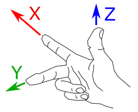
-
Positive rotations are counterclockwise.
-
Negative rotations are clockwise. This is summed up by this diagram:
-
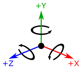
-
When doing a rotation around an axis, there is also a right-hand rule mnemonic to know what is the positive rotation direction: Point the thumb along the rotation axis in its positive direction, and the curl of the fingers (up to the finger nails) represent the positive rotation direction.
-
 When Text option is not associated to _DIR:
 -
Final Robot Tip Z-axis is assigned with Virtual Frame Z-axis (third matrix column vector).
-
During motion processing, only Robot Tip Z-axis will follow its programmed orientation. When Text option is associated to _DIR:
-
From the result of a rotation sequence and associated Virtual Frame matrix, it is possible to choose two Virtual Frame axes (or matrix column vectors) that will be assigned as Final Robot Tip axes (see SetRobotInputVecOrder). AUTO: The automatic solution (old logic) where Vericut can resolve the input type, when calling these macros to program Robot Tip angles:
-
IVector, JVector, KVector, IJKVector (it will set input type to IJK)
-
PQRVector (it will set input type to IJK_DIR)
-
ABCPos (it will set input type to XYZF_ABC)
-
WxyzPos (it will set input type to WXYZ_DIR) IJK & IJK_DIR:
-
Virtual Frame Z-axis will be programmed from IJK unit vector coordinates (see IVector, JVector, KVector, IJKVector).
-
IJK_DIR allows to program full orientation of the Virtual Frame, through Virtual Frame Y-axis that will be programmed from PQR unit vector coordinates (see PQRVector). ZYZF_ABC_DIR:
Note — "L" means "Local" / intrinsic rotations, based on natural order of angles C, B, A.
-
It allows to program orientation of the Robot Tip, using a particular kind of Tait-Bryan angles elemental rotations: X-Y-Z.
-
Tait-Bryan angles are common in engineering applications, and apply rotations on all 3 axes.
-
It will use programmed C, B, A angles (see ABCPos).
-
We begin to build Virtual Frame orientation, from current state of Program Zero. Rotation sequence can be interpreted using, at each new step, the previously rotated Virtual Frame (intrinsic rotations):
-
1. Rotation about Program Zero X-axis, with angle C (Roll).
-
2. Rotation about the new Virtual Frame (rotated from last step) Y-axis, with angle B (Pitch).
-
3. Rotation about the new Virtual Frame (rotated from last step) Z-axis, with angle A (Yaw). It can also be interpreted using stationary Program Zero axes (extrinsic rotations):
-
1. Rotation about stationary Program Zero Z-axis, with angle A.
-
2. Rotation about stationary Program Zero Y-axis, with angle B.
-
3. Rotation about stationary Program Zero X-axis, with angle C. WXYZ_DIR:
-
It allows to program orientation of the Robot Tip, using a unit quaternion vector.
-
It will use programmed quaternion vector (see WxyzPos).
-
This quaternion vector is converted into the rotation matrix of the Virtual Frame.
SetRobotInputVecOrder
-
Function — MISCELLANEOUS
-
Status — ACTIVE
-
Input —
- Text: 3 values – each being TLVEC, IGNORE, or DIRVEC
- Value: Not Used
-
Comment — Added V7.2.3
-
Input —
- Text: 3 values – each being TLVEC, IGNORE, or DIRVEC
- Value: Not Used
This macro is used to define which axes of the input virtual matrix are used to drive the robot head. When the robot head/tool is a tape roller, water jet bracket or similar end effector, the full orientation of the robot tip / tool is programmed. For details see macro SetRobotInputType.The matrix XYZ vectors can be applied differently. For instance:
-
When the input type is XYZF_ABC or XYZF_CBA, the used vector is Z (tool vector) and the XY are ignored.
-
With input type XYZF_ABC_DIR or XYZF_CBA_DIR, two vectors from matrix are used and this macro assigns vectors to its destination.
-
The Override Text string contains 3 words in the order of Virtual Frame ZYX vectors, so the first word is associated with Virtual Frame Z-axis and the last word with Virtual Frame X-axis. Valid words are TLVEC, DIRVEC and IGNORE:
-
TLVEC is associated to Final Tip Z-axis; Its position in the Text field tells where to pick it, from Virtual Frame matrix (using order ZYX).
-
DIRVEC is associated to Final Tip Y-axis; Its position in the Text field tells where to pick it, from Virtual Frame matrix (using order ZYX). Default order is straightforward association, equivalent to Override Text = TLVEC DIRVEC IGNORE:
-
Final Robot Tip Z-axis (associated to TLVEC) is assigned with Virtual Frame Z-axis (TLVEC has first position in the Text field, which is associated to Virtual Frame Z-axis).
-
Final Robot Tip Y-axis (associated to DIRVEC)is assigned with Virtual Frame Y-axis (DIRVEC has second position the Text field, which is associated to Virtual Frame Y-axis).
-
Final Robot Tip X-axis is implicitly recomputed. For VCS with a tape roller programmed by VCP, correct convention is Override = TLVEC IGNORE DIRVEC:
-
Final Robot Tip Z-axis (associated to TLVEC) is assigned with Virtual Frame Z-axis (TLVEC has first position in the Text field, which is associated to Virtual Frame Z-axis).
-
Final Robot Tip Y-axis (associated to DIRVEC) is assigned with Virtual Frame X-axis (DIRVEC has second position the Text field, which is associated to Virtual Frame Y-axis).
-
Final Tip X-axis is implicitly recomputed. For a water jet head with an angle tool the Override Text =DIRVEC IGNORE TLVEC:
-
Final Robot Tip Z-axis (associated to TLVEC) is assigned with Virtual Frame X-axis (TLVEC has first position in the Text field, which is associated to Virtual Frame X-axis).
-
Final Robot Tip Y-axis (associated to DIRVEC) is assigned with Virtual Frame Z-axis (DIRVEC has second position the Text field, which is associated to Virtual Frame Z-axis).
-
Final Tip X-axis is implicitly recomputed.
Note — This macro should be called in the Start of Processing event, and/or any later event.
SetRobotLinearAxisMode
-
Function — MOTION
-
Status — ACTIVE
-
Input —
- Text: FIRST, SECOND, THIRD, XAXIS, YAXIS, ZAXIS, MIXED, SEPARATE,ON, OFF, AT
- Value: None
-
Comment — Added V7.3.1
-
Input —
- Text: See description below
- Value: Used to specify the linear axis position for options AT
This macro is provides the same functionality provided by the SetRobotXAxisMode macro except that it can be used to set up to 3 linear axes.
The first argument is either FIRST, SECOND, or THIRD
The second argument is either XAXIS, YAXIS, or ZAXIS
The third argument is either ON, OFF, MIXED, or SEPARATE
The following are the details on each argument:
FIRST – Selects first logical linear axis.
SECOND – Selects second logical linear axis.
THIRD – Selects third logical linear axis.
XAXIS – Selected logical linear axis will become associated to an “X Linear” component if it exists. Else, it will be associated to an “U Linear” component. If both the “X Linear” and “U Linear” components exist, the “X Linear” component is chosen.
YAXIS – Selected logical linear axis will become associated to an “Y Linear” component if it exists. Else, it will be associated to an “V Linear” component. If both the “Y Linear” and “V Linear” components exist, the “Y Linear” component is chosen.
ZAXIS – Selected logical linear axis will become associated to an “Z Linear” component if it exists. Else, it will be associated to an “W Linear” component. If both the “Z Linear” and “W Linear” components exist, the “Z Linear” component is chosen.
MIXED – The robot’s linear axis is set as programmed by linear axis code.
SEPARATE – Obsolete, offers exact same management as MIXED.
ON – To be used exclusively with the first logical linear axis, when it represents the main horizontal track for the robot.  Activates the linear axis and locks the first robot rotary at its current position.  Position along the linear axis will be automatically computed.
OFF – Deactivates the linear axis (locks at its current position) and activates the first rotary axis.
AT – Optional, activates the linear axis and programs the specified position.
Example —
To set one axis apply:
- SetRobotLinearAxisMode OT=FIRST XAXIS ON/OFF/MIXED/SEPARATE AT(optional)
And to set another one use:
- SetRobotLinearAxisMode OT=SECOND YAXIS ON/OFF/MIXED/SEPARATE AT(optional)
Note — This macro should be called in the Start of Processing event, and/or any later event.
SetRobotLinearPos
-
Function — MOTION
-
Status — OBSOLETE
-
Input —
- Text: FIRST – Selects first logical linear axis (which is the default, if Text is unused)
- Value: Linear position
-
Comment — Added V7.2, obsolete since V9.4 with robot logic version 3
-
Input —
- Text: FIRST – Selects first logical linear axis (which is the default, if Text is unused)
- Value: Linear position
This macro is obsolete for new projects using the version 3 of the robot logic. For them, the “AxisMotion” macros must be used. For projects using the version 1 or 2 of the robot logic, this macro is used to set a linear axis value for a robot on a rail. In some cases a robot’s position along linear axis can be programmed in a block together with the Cartesian XYZ position to force the robot’s base to be in a particular place. This macro allows the setting of the linear position of the robot base relative to the selected logical axis. If it is followed with Inverse Kinematics motion, robot rotary joints are rotated at calculated angle to achieve the programmed Cartesian XYZ position.
See also — SetRobotLinearAxisMode and SetRobotXAxisMode
SetRobotLogicVersion
-
Function — MISCELLANEOUS
-
Status — ACTIVE
-
Input —
- Text: Not Used
- Value: - 1 = Version 1 of robot logic (legacy, from before V9.2).
-
Comment — Added V9.2
-
Inputs —
- Text: Not Used
- Value:
- 1 = Version 1 of robot logic (legacy, from before V9.2)
- 2 = Version 2 of robot logic (from V9.2)
- 3 = Version 3 of robot logic (from V9.4)
- 4 = Version 4 of robot logic (from V9.6)
This macro sets the version to be used for robot logic. In case a new version impacts the behavior of robot logic, this macro allows to keep the behavior associated to an older version.
Note — With robot, this macro must be called in the Reset event.
SetRobotMaxSumTipDeltaAngles
-
Function — MOTION
-
Status — ACTIVE
-
Input —
- Text: Not used
- Value: The maximum sum of delta angles of the tip for linear motion from which a warning is displayed. A value of 0 means that the sum is not checked and no warning is displayed
-
Comment — Added 9.3
-
Input —
- Text: Not used
- Value: The maximum sum of delta angles of the tip for linear motion from which a warning is displayed. A value of 0 means that the sum is not checked and no warning is displayed
Sets the maximum sum of delta angles of the tip allowed between two linear motions, in order to prevent bad motions with the real controllers.
SetRobotMotionType
-
Function — MOTION
-
Status — ACTIVE
-
Input —
- Text: PTP = Point To Point positioning with Inverse Kinematics.
- Value: None
-
Comment — Added V7.1
-
Input —
- Text:
- PTP = Point To Point positioning with Inverse Kinematics.
- LIN = Linear Interpolation with Inverse Kinematics
- FK = Forward Kinematics / Direct Drive of axis
- CIRC = Circular interpolation with inverse kinematics
- Value - Not used, except for obsolete configuation style (if Text is unused)
- 0 = FK
- 1 = LIN
Note — Configuration through Text field doesn't imposes combined use of macro CartesianModeOnOff: - With Forward Kinematics, call CartesianModeOnOff V=0 - With Inverse Kinematics, call CartesianModeOnOff V=1
Note — Configuration through Value field imposes combined use of macro CartesianModeOnOff: - With Forward Kinematics, call CartesianModeOnOff V=0 - With Inverse Kinematics, call CartesianModeOnOff V=1
This macro is used to specify the motion type of the robot's Tip Point when moving it from point A to point B. Currently, following motions are supported: FK (Forward Kinematics / Axis Direct Drive):
-
FK motion moves an axis directly. PTP (Point To Point) positioning:
-
PTP motion moves all of the robot's rotary axes simultaneously and synchronously. The Tip Point moves along a complex and rather chaotic curve trajectory. It is the fastest way for a robot to reach a programmed Tip position. LIN (Linear Interpolation):
-
LIN motion moves the Tip Point in very small intervals producing a linear trajectory between points A and B. The robot's Tip orientation is also linearly interpolated.
-
The accuracy of linear motion is based on Rotary Motion Tolerance set in Properties dialog.
-
CIRC (Circular interpolation)
-
CIRC motion moves the tip along a circle arc between points A and B. The robot tip orientation is linearly interpolated.
The accuracy of circular motion is based on Rotary Motion Tolerance in the Properties dialog
SetRobotRotisAxisMode
-
Function — MOTION
-
Status — ACTIVE
-
Input —
- Text: ON – activates part rotary axis.
- Value: Use to specify the contact point angle relative to the machine axis perpendicular to the axis of rotation.
-
Comment — Added 7.1
-
Input —
- Text: ON – activates part rotary axis.
- Value: Use to specify the contact point angle relative to the machine axis perpendicular to the axis of rotation.
This macro is used to activate, or deactivate, an optional rotary axis unit where the part is mounted. If there is more than one rotisserie in the project, robot logic will use the rotisserie associated to the active stock; This active stock can be set through the macro SetActiveStockName. When an Override Text value of ON is specified, the part can be rotated about the X axis. To restrict ambiguity in tool positioning there is a requirement that TTP (Tool Tip Point) contact point must be at specific angle relative to the X rotary axis. This requirement must be satisfied at any time during the motion and at a final position as well. When an Override Text value of MIXED is specified, the robot’s rotisserie axis is set as programmed by rotary axis code. The rotisserie axis position must be set using the RotationAngle macro. The robot’s Roller/Tool tip is positioned at the point programmed as Cartesian XYZ position. The rotisserie position usually affects the Stock (Program Zero) coordinate system where XYZ is defined. When an Override Text value of OFF is specified, it will deactivate rotisserie management associated to robot logic. When an Override Text value of PZFIXED is specified after ON or MIXED, robot logic will take into account the fact that Program Zero is not rotating with rotisserie axis.
Note — This macro should be called in the Start of Processing event, and/or any later event.
SetRobotRotisCompPos
-
Function — MOTION
-
Status — OBSOLETE
-
Input —
- Text: Rotisserie component name (rotary or linear axis)
- Value: Position around (rotary axis) or along (linear axis) the rotisserie component axis
-
Comment — Added 9.3, obsolete since 9.4 with robot logic version 3
-
Input —
- Text: Rotisserie component name (rotary or linear axis)
- Value: Position around (rotary axis) or along (linear axis) the rotisserie component axis
Robot logic allows to manage a rotisserie as a kinematic chain of rotary axes and linear axes. This macro is obsolete for new projects using the version 3 of the robot logic. For them, the “AxisMotion” macros must be used. For projects using the version 1 or 2 of the robot logic, this macro is used to specify a target position of a given rotisserie axis component during a PTP, LIN or CIRC motion.
Example — that sets positions for a rotisserie made of three rotary components UX, UY and UZ: G1 X400 Y-300 Z15 A0 B0 C0 UX30 UY20 UZ-10 It will do a linear motion. At the end of the motion, UX is turned at 30°, UY at 20° and UZ at -10°.
SetRobotShoulder
-
Function — MOTION
-
Status — ACTIVE
-
Input —
- Text: None
- Value: Not used
-
Comment — Added 9.4
-
Input —
- Text:
- Value: Not used
This macro specifies what orientation of the robot shoulder (1st joint) should be used to position the End Effector.
When the text value is FORWARD, the shoulder is oriented so that the projection of the A2 joint on the motion plane of A1 is between A1 and the projection of the A5 joint on the plane of A1. This is the default behavior.
When the text value is BACKWARD, the projection of the A2 joint on the motion plane of A1 is outside the line segment between A1 and the and the projection of the A5 joint on the plane of A1.
The figure below illustrates, on the left, the forward, and on the right, the backward shoulder positions. Both the projections of the A5 and the A2 joints on the A1 motion plane are noted A5’ and A2’ respectively.
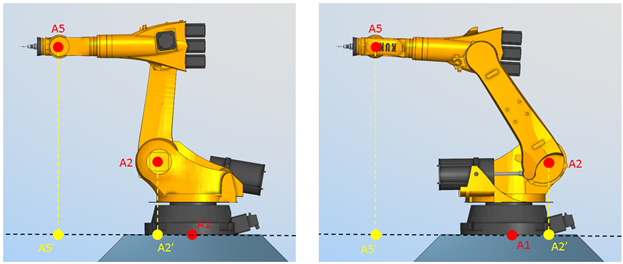
SetRobotSingularityTol
-
Function — MISCELLANEOUS
-
Status — ACTIVE
-
Input —
- Text: Not Used
- Value: Tolerance
-
Comment — Added V7.3
-
Input —
- Text: Not Used
- Value: Tolerance
This macro is used to set a tolerance for the detection of robot singularities. The Override Value is used to specify the minimum angle, in degrees, when a warning is generated. The default value is 0.01812 as specified in KUKA documents.
Note — This macro should be called in the Start of Processing event, and/or any later event.
SetRobotTipCsys
-
Function — MOTION
-
Status — ACTIVE
-
Input —
- Text: The name of a coordinate system, or the name of a component representing the coordinate system.
- Value: Not Used
-
Comment — Added V7.1
-
Input —
- Text: The name of a coordinate system, or the name of a component representing the coordinate system.
- Value: Not Used
This macro is used to specify a coordinate system that is to be used to orient the robots’ End Effector (origin) where the Tool, or Part, is attached. Enter the name of csys, or the name a component whose coordinate system will be used as the csys, in the Override Text field. The coordinate system must be defined in the Project Tree. Using components to specify the csys is convenient when configuring a multi-system project.
See also — SetRobotBaseCsys and SetRobotCsys Note — This macro should be called in the Reset event.
SetRobotToolOffsets
-
Function — MISCELLANEOUS
-
Status — ACTIVE
-
Input —
- Text: See entry below.
- Value: Not used.
-
Comment — Added in V8.2
-
Input —
- Text: See entry below.
- Value: Not used.
This macro is used in robot logic to control tool offset data from Tool Manager. Since robot drives Tool Tip Csys in general we don’t need to use tool offsets in most cases. However it is useful with 5 axis robot and milling tool. More sophisticated configurations in VCS or VDAF usually have complex angle head with roller or special tool. For these cases using directly TT Csys solves complete offset vector and data from Tool Manager should be ignored. To ignore tool offsets use OT=IGNORE, to apply tool offsets use OT=APPLPY. The default is APPLY.
Note — This macro should be called in the Start of Processing event, and/or any later event.
SetRobotTurnFlags
-
Function — MISCELLANEOUS
-
Status — ACTIVE
-
Input —
- Text: Not Used
- Value: Bit flags corresponding to the robot joints
-
Comment — Added V7.3
-
Input —
- Text: Not Used
- Value: Bit flags corresponding to the robot joints
This macro is used to select which direction a robot joint should move when multiple solutions for robot joints are available to solve the programmed PTP motion in a Cartesian coordinate system (XYZ ABC). This macro corresponds directly to the T field used in the KRL PTP E6POS or E12POS data structure. The Override Value is an integer number which corresponds to a robot joints using bit position (bitwise). Bit position 0 corresponds to joint A1 while bit 5 to joint A6. When a bit value is 0 (not set) a positive solution (angle >= 0) is selected, bit value 1 selects the negative solution. For example, Override Value = 26 in binary format is 011010 and selects A1 positive, A2 negative, A3 positive, A4 negative, A5 negative and A6 positive.
Note — This macro should be called in the Start of Processing event, and/or any later event.
SetRobotXAxisMode
-
Function — MOTION
-
Status — OBSOLETE
-
Input —
- Text: MIXED, SEPARATE, ON, OFF, AT
- Value: None
-
Comment — Use macro SetRobotLinearAxisMode instead for more flexibility
-
Input —
- Text: MIXED, SEPARATE, ON, OFF, AT (Use only one option per group)
- MIXED - The robot's linear axis is set as programmed by linear axis code
- SEPARATE – Obsolete, offers exact same management as MIXED.
- ON – To be used exclusively with a linear axis that represents the main horizontal track for the robot. Activates the linear axis and locks the first robot rotary at its current position. Position along the linear axis will be automatically computed.
- OFF – Deactivates the linear axis (locks at its current position) and activates the first rotary axis.
-
AT – Optional, activates the linear axis and programs the specified position.
-
Value - Used to specify linear axis position for option AT.
This macro is used to activate an optional linear axis unit for some robots. The robot is mounted on a rail and is driven by an additional servomotor along the rail which is usually the X axis. The additional degree of freedom is controlled by this macro. When the X axis is activated, the robot moves along the X axis and its first rotary axis (vertical) is locked. When the X axis is disabled, the robot stays at its current X position and its first rotary axis is activated.
See Also — SetRobotLinearAxisMode
Note — This macro should be called in the Start of Processing event, and/or any later event.
SetRotationPlaneZVectorVars
-
Function — MISCELLANEOUS
-
Status — ACTIVE
-
Input —
- Text: names of 3 variables space separated, followed by an optional Rotation Plane Identifier
- Value: Not Used
-
Comment — Added V7.4.2
-
Input —
- Text: names of 3 variables space separated, followed by an optional Rotation Plane Identifier
- Value: Not Used
Sets the 3 specified variables with the contents of the specified Rotation Plane matrix. The order of the variables is: I, J, K. This can be used if we want to verify the orientation of a Rotation Plane.
SetSavedMotionType
-
Function — MOTION
-
Status — ACTIVE
-
Input —
- Text: Not Used
- Value: Not Used
-
Comment — Added V7.0
-
Input —
- Text: Not Used
- Value: Not Used
This macro is used to save the current motion type which can be later restored by the RestoreSavedMotionType macro. This macro is generally used where the motion type before entering a subroutine needs to be restored when the subroutine motions are completed (for example: palette changer or tool changer).
SetSubsystemID
-
Function — MISCELLANEOUS
-
Status — ACTIVE
-
Input —
- Text: Subsystem ID
- Value: Not Used
This macro is used to set the current subsystem to the input text string value. This changes the active control.
SetSubsystemIDScan
-
Function — MISCELLANEOUS
-
Status — ACTIVE
-
Input —
- Text: Subsystem ID
- Value: Not Used
-
Comment — Added V8.1
-
Input —
- Text: Subsystem ID
- Value: Not Used
This macro is used to set the current subsystem to the input text string value. This changes the active control. This macro is identical to SetSubsystemID, except this macro is processed during the scan pass It is intended that this macro only be used within initialization files. Within initialization files, this macro should be used rather than SetSubsystemID.
SetTableCoord
-
Function — TABLES
-
Status — ACTIVE
-
Input —
- Text: Table name to be set
- Value: Not Used
The text string contains the table name to be set. This macro sets the entry (specified by TableIndex) in this table to the values specified with the WorkCoord...Value macros. Nine values will be stored in the table. Any value not set in the block will be assumed to be zero.
SetTableValues
-
Function — TABLES
-
Status — ACTIVE
-
Input —
- Text: Table name to be set
- Value: Not Used
This macro sets the entry (specified by TableIndex in this table) to the values specified in TableValues. The order of the values passed to TableValues will be the order stored in the table. The number of values stored will be equal to the number of times TableValues was called on this block. Use the Override Text field to specify the name of the table.
Note — S: 1. TableIndex and TableValues must be called before calling SetTableValues. The order in which TableIndex and TableValues macros are called is not significant, as long as they are called before calling SetTableValues.
SetToolNumVar
-
Function — VARIABLES
-
Status — ACTIVE
-
Input —
- Text: Variable to be set
- Value: Not Used
When passed a variable to be set, this macro will set this variable to be the current tool number. Typically, this would be called immediately after ToolChange.
SetVcMultiTools
-
Function — TOOLING
-
Status — ACTIVE
-
Input —
- Text: Not Used
- Value: 1 = Cut with all tools
-
1 = Cut with all tools
- Any other value = Cut with only the active tool (Default)
When passed a value of 1, Vericut will cut with all tools defined on the machine (up to 32 tools) at every block.
SetWorkCoord
-
Function — WORK OFFSETS
-
Status — ACTIVE
-
Input —
- Text: Not Used
- Value: Not Used
This macro is used to set the Base Work Offset and the Work Offset tables (ref. Base work Offsets table and Work Offsets table in the Tables for Processing G-Codes section, in the Vericut Help Library). The Register value is set by the WorkCoordIndex macro, and the Sub-Register value is set by the TableSubRegisterValue macro, and the offset is set with the WorkCoord[XYZABCUVWA2B2C2]Value macros. If the register value is 0, the Base Work Offset will be set. If the register value is a value from 1-6, the corresponding Work Offset will be set.
Example — Register 54 in the Work Offset table is set to: "From: Tool To: Stock" (which equates to X0 Y0 Z-20)
In the NC Program we read:
-
G10L2P1 X0 Y10 Z-19
-
This lines tells us to set the Register 54 offset in the Work Offset table to: (X0 Y10 Z-19)
-
Since this Register already exists in the Work Offset table, and it is defined as relational, we will now update the additional offset for this entry so that the total offset is equal to the specified offset (X0 Y10 Z-19).
-
The Register 54 entry in the Work Offset Table is updated to: Tool To: Stock, Offset= X0 Y10 Z1 Note — register values 1-6 sets registers 54-59 in the Work Offset table. All other values, other then 0-6, are invalid. If the table entry is defined as a "relational" offset ( from …. to …), then the corresponding offset will be kept as relational and an additional offset will be added so that the total offset matches what is being specified. If the table entry is defined as a non-relational offsets, it will be kept as a non-relational offset. If the table entry is not previously defined, it will be set as non-relational.
SetZeroForRpcpDWO
-
Function — SHIFT WORK PZ
-
Status — ACTIVE
-
Input —
- Text: Not Used
- Value: 0 = clear the saved orientation, 1 = save the current orientation
-
Comment — ADDED in V8.0
-
Input —
- Text: Not Used
- Value: 0 = clear the saved orientation, 1 = save the current orientation
This macro sets and clear the “Zero” that is to be used with RPCP and DWO. When called with a value of 1, the current orientation is saved and RPCP and DWO will be based on the delta from this position. When called with a value of 0, the saved orientation is cleared and RPCP and DWO is then based on the stock’s orientation.
Note — Concerning offsets, currently only Relational Offsets supports this feature.
ShortLongOffsetReset
-
Function — CUTTER COMPENSATION
-
Status — ACTIVE
-
Input —
- Text: Not Used
- Value: Not Used
This macro is used to turn off the following macros: CutterCompDoubleLong, CutterCompDoubleShort, CutterCompLong and CutterCompShort.
Siemens3CmdBranch
-
Function — SIEMENS CMD
-
Status — ACTIVE
-
Input —
- Text: Not Used
- Value: Sequence number to branch to
The value passed is the sequence number to branch to. If an additional argument is passed, then it is added to the absolute value of the sequence number. This routine then calls the GotoJumpForwardBackward macro. If more than 2 arguments were passed, then an error message will be printed.
Siemens3CmdIfEqual
-
Function — SIEMENS CMD
-
Status — ACTIVE
-
Input —
- Text: Not Used
- Value: Sequence number to branch to
The value passed is the sequence number to branch to. If argument 1 is equal to argument 2, then GotoJumpForwardBackward is called to branch to the specified sequence number. If an additional argument is passed, then it is added to the absolute value of the sequence number. If less than 2 arguments, or more than 3 arguments were passed, then an error message will be printed.
Siemens3CmdIfGreater
-
Function — SIEMENS CMD
-
Status — ACTIVE
-
Input —
- Text: Not Used
- Value: Sequence number to branch to
The value passed is the sequence number to branch to. If argument 1 is greater than argument 2, then GotoJumpForwardBackward is called to branch to the specified sequence number. If an additional argument is passed, then it is added to the absolute value of the sequence number. If less than 2 arguments, or more than 3 arguments were passed, then an error message will be printed.
Siemens3CmdIfGreaterEqual
-
Function — SIEMENS CMD
-
Status — ACTIVE
-
Input —
- Text: Not Used
- Value: Sequence number to branch to
The value passed is the sequence number to branch to. If argument 1 is greater than or equal to argument 2, then GotoJumpForwardBackward is called to branch to the specified sequence number. If an additional argument is passed, then it is added to the absolute value of the sequence number. If less than 2 arguments, or more than 3 arguments were passed, then an error message will be printed.
Siemens3LoadAddress
-
Function — SIEMENS CMD
-
Status — ACTIVE
-
Input —
- Text: Not Used
- Value: 1 = X axis, 2 = Z axis
This macro is used to set the contents of the address parameter specified by macro Siemens3SetAddressParm to the specified value. If a variable argument is specified, it will override the input value. A value of 1 corresponds to the X axis and a value of 2 corresponds to the Z axis.
Siemens3PreProcessor
-
Function — MISCELLANEOUS
-
Status — OBSOLETE
-
Input —
- Text: None
- Value: None
-
Comment — Use macro SetPreProcessorType instead.
Siemens3SetAddressParm
-
Function — SIEMENS CMD
-
Status — ACTIVE
-
Input —
- Text: Not Used
- Value: Address Parameter
This macro is used to set the address parameter that will be accessed (90-93). This is necessary since @90 command might be followed by 2 values (@90 0 R10). This allows for @90 to be defined as a word. This word can then have a value and an optional variable argument.
Siemens3TAddressAxis
-
Function — SIEMENS CMD
-
Status — ACTIVE
-
Input —
- Text: Not Used
- Value: Axis value
This macro is used to call the corresponding "AxisMotion" macro (AAxisMotion, BAxisMotion), etc) with the specified value. If a variable argument is specified, it will override the input value. The axis to move is specified by contents of the specified address parameter. The address parameter is set using the Siemens3SetAddressParm macro.
Siemens840DCallSubName
-
Function — SUBROUTINES
-
Status — ACTIVE
-
Input —
- Text: Name of subroutine to call
- Value: Not Used
-
Comment — Added V7.3.3
-
Input —
- Text: Name of subroutine to call
- Value: Not Used
This macro strips the pathname, the “N” suffix if it exists, and any Sin840D specific suffixes, and then calls the corresponding subroutine. Recognized Sin840D suffixes include: _MPF, _SPF, _TEA, _SEA, _TOA, _UFR, _INI, _GUD, _RPA, _COM, _DEF
Siemens840DGoto
-
Function — Branching
-
Status — ACTIVE
-
Input —
-
Comment — Added V7.0.1
-
Input —
This macro is for the Siemens 840D GOTO/GOTOF/GOTOB command. If the text argument is an 'N' followed by a number, then a goto sequence will be processed. Otherwise a goto label will be processed. The value determines the direction of the search.
Notes — - Since the text argument defines the label or sequence number, no other macro calls are needed to set label or sequence number to branch to. - The GOTO, GOTOF, GOTOB, GOTOC words needs to be defined as having an alpha-numeric argument.
Siemens840DGoto2
-
Function — BRANCHING
-
Status — ACTIVE
-
Input —
-
Comment — Added V7.0.1
-
Input —
This macro is for the Siemens 840D GOTO/GOTOF/GOTOB command. This macro is identical to Siemens840DGoto macro except this macro has the error check for numeric value.
If the text argument begins with a numeric value, an error will be given. If the text argument is an 'N' followed by a number, then a goto sequence will be processed. Otherwise a goto label will be processed.
The value determines the direction of the search.
Notes — - Since the text argument defines the label or sequence number, no other macro calls are needed to set label or sequence number to branch to. - The GOTO, GOTOF, GOTOB, GOTOC words needs to be defined as having an alpha-numeric argument.
Siemens840DGotoSuppress
-
Function — BRANCHING
-
Status — ACTIVE
-
Input —
-
Comment — Added V9.4.2
-
Input —
This macro is for the Siemens 840D GOTOC command. This macro is identical to Siemens840DGoto macro except no error message will be given if the sequence number or label is not found.
If the text argument is an 'N' followed by a number, then a goto sequence will be processed. Otherwise a goto label will be processed. The value determines the direction of the search.
Notes — - Since the text argument defines the label or sequence number, no other macro calls are needed to set label or sequence number to branch to. - The GOTO, GOTOF, GOTOB, GOTOC words needs to be defined as having an alpha-numeric argument.
Siemens840DGotoSuppress2
-
Function — BRANCHING
-
Status — ACTIVE
-
Input —
-
Comment — Added V9.4
-
Input —
This macro is for the Siemens 840D GOTOC command. This macro is identical to Siemens840DGotoSuppress macro except this macro has the error check for numeric value.
If the text argument begins with a numeric value, an error will be given. If the text argument is an 'N' followed by a number, then a goto sequence will be processed. Otherwise a goto label will be processed. The value determines the direction of the search.
Notes — - Since the text argument defines the label or sequence number, no other macro calls are needed to set label or sequence number to branch to. - The GOTO, GOTOF, GOTOB, GOTOC words needs to be defined as having an alpha-numeric argument.
Siemens840DProc
-
Function — SUBROUTINES
-
Status — ACTIVE
-
Input —
- Text: Subroutine name optionally followed by a series of arguments enclosed by parenthesis.
- Value: Not Used
This macro processes a Siemens 840D PROC statement. This includes the processing of all the input Arguments.
The typical scenario would be:
-
Define the Word: PROC with a subtype of Alpha-Numeric + Arguments.
-
In the Word Address table, the PROC word will call this macro.
Siemens840DProcCall
-
Function — SUBROUTINES
-
Status — ACTIVE
-
Input —
- Text: Subroutine name, optionally followed by a series of arguments enclosed by parenthesis.
- Value: Not Used
This macro is called when calling a Siemens 840D subroutine (PROC). The text argument passed should be the subroutine name, optionally followed by a series of arguments enclosed by ( ).
Note — This is a black box parser. The user has no flexibility on what can or cannot be parsed. The typical scenario would be:
-
- Define the Word: SubroutineName with a subtype of Alpha-Numeric + Arguments.
-
- When an undefined word is found, a check is made to see if it matches a subroutine name. If it does, and SubroutineName exists in the word list, then it will associate the value that follows with the SubroutineName word.
-
- In the Word Address table, this word should then call the above macro.
Siemens840DSubroutineProc
-
Function — SUBROUTINES
-
Status — ACTIVE
-
Input —
- Text: Subroutine name
- Value: Not used
-
Comment — Added in V9.0
-
Input —
- Text: Subroutine name
- Value: Not used
This macro was designed to work with a Siemens 840D “%N” statement. This macro strips any suffix, and calls either SubroutineSequence or Siemens840DProc. SubroutineSequence is called for _MPF, otherwise Siemens840dProc is called. Supported suffixes include: _MPF, _SPF, _TEA, _SEA,_TOA, _UFR, _INI, _GUD, _RPA, _COM, _DEF
SiemensActualSpindle
-
Function — FEEDS & SPEEDS
-
Status — ACTIVE
-
Input —
- Text: Not Used
- Value: Value of Active Spindle
Marks which spindle this controller is currently working on. If this spindle has previously been marked as being controlled by this controller, this controller will now takes control. (M*=26)
This macro:
-
- Sets a Siemens internal value defining the actual spindle.
-
- Passes the spindle number as the numeric value.
-
- Restores the internal spindle speed for this channel if the speed for this spindle is being controlled by this channel.
-
- Sets the controlling head (sync mode).
Note — SetActiveSpindleName should also be called.
SiemensAMIRROR
-
Function — MISCELLANEOUS
-
Status — ACTIVE
-
Input —
- Text: Not Used
- Value: Not Used
Updates the MI (mirror) values of $P_PFRAME based on previous input from the SiemensFrameAxisArgument macro. For all fields specified, the mirroring will be toggled (turn off if it is on, or turned on if it is off). It then updates the $P_ACTFRAME (sum of all System FRAMES), and updates the local coordinates. For an example of how arguments are passed, see SiemensFrameAxisArgument.
SiemensApplyRotaryOffsets
-
Function — WORK OFFSETS
-
Status — NOT RECOMMENDED
-
Input —
- Text: The name of 2 variables which contains rotary positions (space separated)
- Value: 0 = call WorkCoord, otherwise execute this macro
-
Comment — Added V8.1
-
Input —
- Text: The name of 2 variables which contains rotary positions (space separated)
- Value: 0 = call WorkCoord, otherwise execute this macro
This is an old macro that was based off of the old IJK to ABC logic. It has been replaced by SiemensApplyRotaryOffsets2 which is based on the new IJK to Angles logic. The following is a simple description of this macro. Since this macro has been replaced, this description does not attempt to describe all the flags that can modify how this macro behaves. If passed a value of zero, the macro WorkCoord is called with the current work coordinate value. Otherwise, this macro updates the tool, work and shift offsets as if the machine has already been rotated to the specified positions and as if Dynamic Work Offsets (DWO) were turned on. The inputs variables contain rotary positions for the first and second rotaries as defined by the IJK to ABC logic.
SiemensApplyRotaryOffsets2
-
Function — WORK OFFSETS
-
Status — ACTIVE
-
Input —
- Text: The name of 2 variables which contains rotary positions (space separated)
- Value: Not used
-
Comment — Added in V8.2
-
Input —
- Text: The name of 2 variables which contains rotary positions (space separated)
- Value: Not used
This macro updates the tool, work and shift offsets as if the machine has already been rotated to the specified positions and as if Dynamic Work Offsets (DWO) were turned on. The inputs variables contains rotary positions for the first and second rotaries as defined by the IJK to Angles logic.
Note — This macro does not rotate the machine and it does not turn on DWO.
SiemensApplyToolOffsets
-
Function — WORK OFFSETS
-
Status — ACTIVE
-
Input —
- Text: The name of 2 variables which contains rotary positions (space separated)
- Value: Not used
-
Comment — Added V9.4.1
-
Input —
- Text: The name of 2 variables which contains rotary positions (space separated)
- Value: Not used
This macro updates the tool offsets as if the machine has already been rotated to the specified positions. The inputs variables contains rotary positions for the first and second rotaries as defined by the IJK to Angles logic. This macro is identical to SiemensApplyRotaryOffsets2, except that it only updates the Tool offsets, and not the Work offsets.
Note — This macro does not rotate the machine and it does not turn on DWO.
SiemensArgumentMismatchOnOff
-
Function — MISCELLANEOUS
-
Status — ACTIVE
-
Input —
- Text: Not Used
- Value: 0 = Off (default), 1 = On
-
Comment — Added V9.5
-
Input —
- Text: Not Used
- Value: 0 = Off (default), 1 = On
The macro turns ON/OFF the check for an argument mismatch when calling a Siemens Proc. For example: passing a STRING argument and the function is expecting an INT or a REAL, or passing an INT or REAL argument, and the function is expecting a STRING
Note — We do not check INT vs REAL vs BOOL or STRING vs AXIS
SiemensAROT
-
Function — MISCELLANEOUS
-
Status — ACTIVE
-
Input —
- Text: Not Used
- Value: Not Used
Updates the RT (rotation) values of $P_PFRAME based on previous input from the SiemensFrameAxisArgument macro. The input XYZ rotations are applied to the existing $P_PFRAME orientation, and then new rotation angles are calculated. It then updates the $P_ACTFRAME (sum of all System FRAMES), and updates the local coordinates. For an example of how arguments are passed, see SiemensFrameAxisArgument.
SiemensASCALE
-
Function — MISCELLANEOUS
-
Status — ACTIVE
-
Input —
- Text: Not Used
- Value: Not Used
Updates the SC (scale) values of $P_PFRAME based on previous input from the SiemensFrameAxisArgument macro. The current scale values are multiplied by the input scale values. It then updates the $P_ACTFRAME (sum of all System FRAMES), and updates the local coordinates. For an example of how arguments are passed, see SiemensFrameAxisArgument.
SiemensATRANS
-
Function — MISCELLANEOUS
-
Status — ACTIVE
-
Input —
- Text: Optional FI
- Value: Not Used
Updates the TR (translate offset) or FI (fine offset) values of the Siemens $P_PFRAME variable based on previous input from the SiemensFrameAxisArgument macro. By default, this macro is setting the TR values. If FI is specified in the Text field, this macro will set the FI values. The input values are in the local $P_PFRAME coordinate system. These values are transformed and then added to the current value. It then updates the $P_ACTFRAME (sum of all System FRAMES), and updates the local coordinates. For an example of how arguments are passed, see SiemensFrameAxisArgument.
SiemensATRANSOption
-
Function — MISCELLANEOUS
-
Status — ACTIVE
-
Input —
- Text: Not used
- Value: See below
-
Comment — Added in V9.0
-
Input —
- Text: Not used
- Value: See below
This macro is used to control the 840D ATRANS command behavior in Vericut. The ATRANS command with XYZ parameters creates $P_PFRAME frame with fine offsets (FI values) . In Vericut the FI values are used to set shift offsets on axes. The total offset values on linear axes contain frame TR values and shifts from frame FI values. Some recent Siemens cases show that ATRANS command can set frame TR values as combined total offset with programmed FI values. To handle both cases correctly SiemensATRANSOption macro can be used. With OV=0 (default) the ATRANS command configured with Siemens_P_PFRAME_FI macro sets FI values and Vericut shifts. With OV=1 same macro is used to calculate total offset combined with FI values but the result is used to update frame TR values. The shift values are set to 0. See also Siemen_P_PFRAME_FI macro.
Note — This macro can be used locally or globally if programmed in Start Events.
SiemensAXISFallbackOnOff
-
Function — MISCELLANEOUS
-
Status — ACTIVE
-
Input —
- Text: Not Used
- Value: 0 = no fallback, 1 = yes fallback (default)
When doing Siemens AXIS to Vericut Register conversion, If we cannot find a matching component for the specified AXIS, traditionally we would then check if the AXIS matches one of Vericut’s register. This check against Vericut’s registers is what is being called the “fallback” mechanism. This macro allows you to either continue using the fallback mechanism, or not use it and produce an error if there is no matching component for the specified AXIS.
SiemensAXISLogic
-
Function — MISCELLANEOUS
-
Status — ACTIVE
-
Input —
- Text: DEBUG (optional)
- Value: 0 = Old logic (default), 1 = New Logic (2020)
-
Comment — Added in V9.1
-
Input —
- Text: DEBUG (optional)
- Value: 0 = Old logic (default), 1 = New Logic (2020)
Specifies the Siemens AXIS logic to use. In 2020, we did a total rewrite of how we handled Siemen’s AXIS. This was done so that we can more closely mimic the real control. To use the new logic significant changes needs to be made to the control. We currently support both the old handling and the new handling. V9.0 controls have been rewritten to use the New logic.
Note — In the future, the old logic might go away.
SiemensAXISMappingOnOff
-
Function — MISCELLANEOUS
-
Status — ACTIVE
-
Input —
- Text: Not Used
- Value: 0 = OFF (default), 1 = ON
-
Comment — Added V8.1
-
Input —
- Text: Not Used
- Value: 0 = OFF (default), 1 = ON
Turns ON and OFF the Siemens AXIS mapping capability. If turned on, the AXIS value will be converted based on the current mapping.
For example:
-
G0 Z-30
-
G0 W80
-
GEOAX(3,W)
-
R10=\(AA_IW[Z] ;\)AA_IW contains the local axis position, Z is an AXIS identifier.
-
With AXIS mapping turned off, R10 would equal -30. With AXIS mapping turned on, R10 would equal 80
SiemensAXISMotion
-
Function — MOTION
-
Status — ACTIVE
-
Input —
- Text: Not used
- Value: Axis value
-
Comment — Added in V9.1
-
Input —
- Text: Not used
- Value: Axis value
The concept is that a specific index into a Siemens AXIS variable has been set, and this now causes the corresponding component to move to the specified Axis value. This macro is very unusual, in that it uses the Word argument. It extracts the index value from this argument, and uses to find a matching component name using the Siemens AXCONF variables. It first checks $MN_AXCONF_MACHAX_NAME_TAB and if a matching component is not found, it searches the $MC_AXCONF_MACHAX_USED table for a matching index value (actually index + 1). If found, it sets the component based on the corresponding entry in the $MC_AXCONF_CHANAX_NAME_TAB. If the component is on the current subsystem, then AxisMotion macro is called. Otherwise, either ProcessCompNameValueSync or ProcessCompNameValueSyncWait is called. If the variable that is being set is AX or POS, then ProcessCompNameValueSyncWait is called. If the variable that is being set is POSA, then ProcessCompNameValueSync is called.
Note — This macro only supports AX, POS, and POSA. Any other input will produce an error.
SiemensAXISRegisterAvailable
-
Function — MISCELLANEOUS
-
Status — ACTIVE
-
Input —
- Text: AXIS (value or expression) variable_name
- Value: Not Used
This macro is passed a SIEMENS AXIS, either directly, or by an expression that equates to a Siemens AXIS. It then tries to map this AXIS to a Vericut component for the current subsystem. If a Vericut motion component is found, then it will convert the component’s register into an index and return this index in the specified variable. If a corresponding Vericut motion component is not found, the variable will be set to -1.
Note — This macro is identical to SiemensAXISToRegisterIndex except it does not produce an error message. The concept is that this could be called to see if a specific AXIS exist within Vericut. The AXIS to component mapping is done using the Siemens AXCONF tables and Vericut’s component tree.
The Vericut component register to index mapping is as follows:
-
X = 1
-
Y = 2
-
Z = 3
-
A = 4
-
B = 5
-
C = 6
-
U = 7
-
V = 8
-
W = 9
-
A2 = 10
-
B2 = 11
-
C2 = 12
-
U2 = 13
-
V2 = 14
-
W2 = 15
-
A3 = 16
-
B3 = 17
-
C3 = 18
SiemensAXISToCompName
-
Function — MISCELLANEOUS
-
Status — ACTIVE
-
Input —
- Text: AXIS (value or expression) variable_name
- Value: Not Used
This macro is passed a SIEMENS AXIS, either directly, or by an expression that equates to a Siemens AXIS. It tries to map this AXIS to a Vericut component for the current subsystem. If a Vericut motion component is found, then it will return the component’s name in the specified variable. If a corresponding Vericut motion component is not found, an ERROR will be given and the variable will be set to “”. The AXIS to component mapping is done using the Siemens AXCONF tables and Vericut’s component tree.
Note — The variable must be defined as a Siemen’s STRING variable (Vericut’s Text variable). For example:
-
DEF STRING _AxisName, _VcCompName
-
_AxisName = X_1
-
CGTECH_MACRO “SiemensAXISToCompName” “_AxisName _VcCompName” 1
SiemensAXISToRegisterIndex
-
Function — MISCELLANEOUS
-
Status — ACTIVE
-
Input —
- Text: AXIS (value or expression) variable_name
- Value: Not Used
This macro is passed a SIEMENS AXIS, either directly, or by an expression that equates to a Siemens AXIS. It then tries to map this AXIS to a Vericut component for the current subsystem. If a Vericut motion component is found, then it will convert the component’s register into an index and return this index in the specified variable. If a corresponding Vericut motion component is not found, an ERROR will be given and the variable will be set to -1. The AXIS to component mapping is done using the Siemens AXCONF tables and Vericut’s component tree.
The Vericut component register to index mapping is as follows:
-
X = 1
-
Y = 2
-
Z = 3
-
A = 4
-
B = 5
-
C = 6
-
U = 7
-
V = 8
-
W = 9
-
A2 = 10
-
B2 = 11
-
C2 = 12
-
U2 = 13
-
V2 = 14
-
W2 = 15
-
A3 = 16
-
B3 = 17
-
C3 = 18
SiemensBasicOriginFrame
-
Function — WORK OFFSETS
-
Status — ACTIVE
-
Input —
- Text: Not Used
- Value: Not Used
-
Comment — Added V6.2.1
-
Input —
- Text: Not Used
- Value: Not Used
This macro is used to link the $P_BFRAME Frame variable with the Vericut Base Work Offset table. The offset values in $P_BFRAME are transferred to Base Work Offset values and the other Frame specific values are used to set the system matrix. The new values become active immediately and remain active until the SiemensSystemFramesCancel macro is called. This macro should be called whenever $P_BFRAME Frame is set or changed.
See Also — SiemensSystemFramesCancel and SiemensSystemFramesRestore
SiemensCmd201
-
Function — SIEMENS CMD
-
Status — Active
-
Input —
- Text: Not Used
- Value: Not Used
-
Comment — Added V6.2
-
Input —
- Text: Not Used
- Value: Not Used
Although this macro is not passed any values directly, it expects 2 arguments from the VariableArgumentand ValueArgument macros. The first argument must be VariableArgument. This macro will set the variable specified in the first argument to the value specified in the second argument.
Note — It is pointless using the @201 command since you can set variables directly without using the @201 command. General "300 Series" NOTES: The following notes apply to all "300 series" macros described below:
-
- All series 300 macros "transfer machine data into R-Parameter". All macros in this series treat machine addresses as variables.
-
- In Machine Simulation, these addresses have no additional meaning. This means that each must be set before they are used.
SiemensCmd300
-
Function — SIEMENS CMD
-
Status — ACTIVE
-
Input —
- Text: Not Used
- Value: Not Used
The NC Machine addresses (@300-@302) are referenced as subsystem 10. See general "300 series" notes.
SiemensCmd302
-
Function — SIEMENS CMD
-
Status — ACTIVE
-
Input —
- Text: Not Used
- Value: Not Used
The NC Machine addresses (@300-@302) are referenced as subsystem 10. See general "300 series" notes.
SiemensCmd303
-
Function — SIEMENS CMD
-
Status — ACTIVE
-
Input —
- Text: Not Used
- Value: Not Used
The Cycle Machine addresses (@303-@305) are referenced starting at subsystem 100. (For example if the command references channel 2, the macro would reference subsystem 102). See general "300 series" notes.
SiemensCmd305
-
Function — SIEMENS CMD
-
Status — ACTIVE
-
Input —
- Text: Not Used
- Value: Not Used
The Cycle Machine addresses (@303-@305) are referenced starting at subsystem 100. (For example if the command references channel 2, the macro would reference subsystem 102). See general "300 series" notes.
SiemensCmd306
-
Function — SIEMENS CMD
-
Status — ACTIVE
-
Input —
- Text: Not Used
- Value: Not Used
The PLC address (@306-@308) are referenced as subsystem 11. See general "300 series" notes.
SiemensCmd308
-
Function — SIEMENS CMD
-
Status — ACTIVE
-
Input —
- Text: Not Used
- Value: Not Used
The PLC address (@306-@308) are referenced as subsystem 11. See general "300 series" notes.
SiemensCmd330
-
Function — SIEMENS CMD
-
Status — ACTIVE
-
Input —
- Text: Order of the axes, for example: XYZAC
- Value: Not Used
This macro is used to process the Siemens @330 command. This macro sets a variable with the value of the associated work offset. It must be passed the order of the Axes as an Override Text value. For example: XYZAC. It also must be passed 4 arguments. See ValueArgument.
The arguments have the following meanings:
-
- variable to be set
-
- offset number (1 for G54 , 2 for G55, 3 for G56, 4 for G57)
-
- axis number (the order of the axis must be specified in the Override Text argument)
-
- Coarse/Fine value (currently ignored)
Example —
-
@330 R81 K1 K2 K0 The second axis value of the G54 offset is loaded into parameter R81.
SiemensCmd331
-
Function — SIEMENS CMD
-
Status — ACTIVE
-
Input —
- Text: Not Used
- Value: Not Used
Note — This macro has been hard coded to work with machines with subsystem "1" for the upper turret, "2" for the lower turret, and "4" for the Z-axis of the subspindle. Subsystems 3 and 5 are not currently supported. See general "300 series" notes above.
SiemensCmd360
-
Function — SIEMENS CMD
-
Status — ACTIVE
-
Input —
- Text: Not Used
- Value: Not Used
This macro assumes the following:
- The workpiece is located at 0 0 0.
- For rotaries, the last rotary move has completed.
-
The following specific component names:
-
Turret 1 X - X1
-
Turret 1 Z - Z1
-
Turret 2 X - X2
-
Turret 2 Z - Z2
-
Counter Spindle Z - Z4
-
Turret 1 Y - Y1
SiemensCmd383
-
Function — SIEMENS CMD
-
Status — ACTIVE
-
Input —
- Text: Not Used
- Value: Not Used
The following are the only arguments that are supported. The corresponding bit flag will be placed into the first argument. ARG 2 | ARG3 | ARG4 | ARG5 | MEANING ---|---|---|---|--- 1 | 32 | 5 | 15 | Z-axis mirroring on channel 1 1 | 32 | 17 | 15 | Z-axis mirroring on channel 2 | | | | See general "300 series" notes.
SiemensCmd400
-
Function — SIEMENS CMD
-
Status — ACTIVE
-
Input —
- Text: Not Used
- Value: Not Used
The NC Machine addresses (@400-@402) are referenced as subsystem 10. See general "400 series" notes.
General "400 Series" NOTES: The following notes apply to all "400 series" macros described below:
-
- All series 400 macros "load values into system storage". All macros in this series treat machine addresses as variables.
-
- In Machine Simulation, these addresses have no additional meaning. This means that each must be set before they are used.
SiemensCmd403
-
Function — SIEMENS CMD
-
Status — ACTIVE
-
Input —
- Text: Not Used
- Value: Not Used
The Cycle Machine addresses (@403-@405) are referenced starting at subsystem 100. (For example if the command references channel 2, the macro would reference subsystem 102). See general "400 series" notes.
SiemensCmd404
-
Function — SIEMENS CMD
-
Status — ACTIVE
-
Input —
- Text: Not Used
- Value: Not Used
The Cycle Machine addresses (@403-@405) are referenced starting at subsystem 100. (For example if the command references channel 2, the macro would reference subsystem 102). See general "400 series" notes.
SiemensCmd430
-
Function — SIEMENS CMD
-
Status — ACTIVE
-
Input —
- Text: Order of the axis, for example: XYZAC
- Value: Not Used
This command is used to process the Siemens @430 command. This command sets the values associated with a specific work offset. It must be passed the order of the axes as an Override Text value. For example, XYZAC. It also must be passed 4 arguments See ValueArgument).
The arguments have the following meanings:
-
- Offset number (1 for G54, 2 for G55, 3 for G56, 4 for G57)
-
- Axis number (the order of the axis must be specified in the Override Text argument
-
- Coarse/Fine value (currently ignored)
-
- Offset value
Example —
-
@430 K1 K2 K0 K500The value 500 is loaded into the G54 offset for the second axis.
SiemensCmdAbs
-
Function — SIEMENS CMD
-
Status — ACTIVE
-
Input —
- Text: Not Used
- Value: Not Used
Take the absolute value of the second argument and stores the result in the variable specified by the first argument. Arguments are set using macros ValueArgument and VariableArgument.
SiemensCmdAngle
-
Function — SIEMENS CMD
-
Status — ACTIVE
-
Input —
- Text: Not Used
- Value: Not Used
Takes the arc tangent of y/x (second/third arguments), and stores the result in degrees in the variable specified by the first argument. Arguments are set using macros ValueArgument and VariableArgument.
SiemensCmdASin
-
Function — SIEMENS CMD
-
Status — ACTIVE
-
Input —
- Text: Not Used
- Value: Not Used
Takes the arc sine of the second argument, and stores the result in degrees in the variable specified by the first argument. Arguments are set using macros ValueArgument and VariableArgument.
SiemensCmdATan
-
Function — SIEMENS CMD
-
Status — ACTIVE
-
Input —
- Text: Not Used
- Value: Not Used
If 2 arguments were passed, takes the atan of the second argument, converts the results to degrees, and stores the result in the first argument. If only one argument was passed, takes the atan of the first argument, converts the results to degrees, and stores the result in the first argument. If no arguments or more than 2 arguments were passed, issues an error message. Arguments are set using macros ValueArgument and VariableArgument.
SiemensCmdBranch
-
Function — SIEMENS CMD
-
Status — ACTIVE
-
Input —
- Text: Not Used
- Value: Not Used
Branches to the location specified by the first argument. Arguments are set using macros ValueArgument and VariableArgument.
SiemensCmdCase
-
Function — SIEMENS CMD
-
Status — ACTIVE
-
Input —
- Text: Not Used
- Value: Not Used
Use this macro to processes a Siemens "Case" statement. The first argument is the value being tested. It is followed by a series of value pairs (value, branch location). If the values match, a branch is made to the specified location. Arguments are set using macros ValueArgument and VariableArgument.
SiemensCmdCos
-
Function — SIEMENS CMD
-
Status — ACTIVE
-
Input —
- Text: Not Used
- Value: Not Used
Takes the cosine of the second argument (in degrees), and store the result in the variable specified by the first argument. Arguments are set using macros ValueArgument and VariableArgument.
SiemensCmdDec
-
Function — SIEMENS CMD
-
Status — ACTIVE
-
Input —
- Text: Not Used
- Value: Not Used
Use to decrement the value of the specified variable. Arguments are set using macro VariableArgument
SiemensCmdGetChannel
-
Function — SIEMENS CMD
-
Status — ACTIVE
-
Input —
- Text: Not Used
- Value: Not Used
This macro returns the current channel number. This macro assumes that the channel number is the subsystem. In our system, the subsystem is an alphanumeric string. Channel numbers are integers. This macro therefore requires that all INDEX machines be built with integer subsystems. (@372)
SiemensCmdGetGCode
-
Function — SIEMENS CMD
-
Status — ACTIVE
-
Input —
- Text: Not Used
- Value: Not Used
This macro will return the G-Code state in variable 1 of the corresponding group specified in variable 3. The channel number in variable 2 is currently being ignored. (@36b)
The following values are returned based on the group:
-
GROUP | VALUES
-
|---
-
0 | 0, 1, 2, 3
-
1 | 9
-
2 | 17, 18, 19
-
3 | 40, 41, 42
-
4 | 53
-
5 | Current Work Offset
-
6 | 4
-
7 | 60
-
8 | 70, 71
-
9 | 80
-
10 | 90, 91
-
11 | 94, 95
-
12 | 147
-
13 | 50
-
14 | 150
-
15 | 130
-
16 | 230
-
17 | 330
-
18 | 930
-
19 | 400
-
20 | 171
-
21 | 175
-
22 | 720
-
23 | 220
-
24 | 450
-
25 | 455
-
27 | 420
-
28 | 600
-
Else | 0
SiemensCmdHypot
-
Function — SIEMENS CMD
-
Status — ACTIVE
-
Input —
- Text: Not Used
- Value: Not Used
Takes the square root of the sum of the squares of the second and third arguments, and stores the result in the variable specified by the first argument. Arguments are set using macros ValueArgument and VariableArgument.
SiemensCmdIfEqual
-
Function — SIEMENS CMD
-
Status — ACTIVE
-
Input —
- Text: Not Used
- Value: Not Used
This macro processes Siemens conditional logic. They are in the form: IF A
SiemensCmdIfGreater
-
Function — SIEMENS CMD
-
Status — ACTIVE
-
Input —
- Text: Not Used
- Value: Not Used
This macro processes Siemens conditional logic. They are in the form: IF A
SiemensCmdIfGreaterEqual
-
Function — SIEMENS CMD
-
Status — ACTIVE
-
Input —
- Text: Not Used
- Value: Not Used
This macro processes Siemens conditional logic. They are in the form: IF A
SiemensCmdIfLess
-
Function — SIEMENS CMD
-
Status — ACTIVE
-
Input —
- Text: Not Used
- Value: Not Used
This macro processes Siemens conditional logic. They are in the form: IF A
SiemensCmdIfLessEqual
-
Function — SIEMENS CMD
-
Status — ACTIVE
-
Input —
- Text: Not Used
- Value: Not Used
This macro processes Siemens conditional logic. They are in the form: IF A
SiemensCmdIfNotEqual
-
Function — SIEMENS CMD
-
Status — ACTIVE
-
Input —
- Text: Not Used
- Value: Not Used
This macro processes Siemens conditional logic. They are in the form: IF A
SiemensCmdInc
-
Function — SIEMENS CMD
-
Status — ACTIVE
-
Input —
- Text: Not Used
- Value: Not Used
Use to increment the value of the specified variable. Arguments are set using the macro VariableArgument).
SiemensCmdIntegral
-
Function — SIEMENS CMD
-
Status — ACTIVE
-
Input —
- Text: Not Used
- Value: Not Used
Use to truncate the decimal contents of the specified variable. Arguments are set using the macro VariableArgument.
SiemensCmdPopVarGroup
-
Function — SIEMENS CMD
-
Status — ACTIVE
-
Input —
- Text: Not Used
- Value: Not Used
Restores a range of NC variables from their saved copies in the 300+n buffer slots. This is the companion "pop" to SiemensCmdPushVarGroup.
Two arguments are required, passed via the Siemens @ command syntax — not via the standard Text or Value inputs:
| Argument | Meaning |
|---|---|
| 1 | First variable number in the range |
| 2 | Last variable number in the range |
For each variable n in the specified range, the value stored in variable 300+n is copied back into variable n. If exactly 2 arguments are not provided, VERICUT outputs an error.
Example —
Copies the contents of variables 361–369 back into variables 61–69.Note — This implementation approximates the Siemens push/pop behavior using a fixed 300+n offset rather than a true stack. It works correctly for variables in the range 0–200.
See also — SiemensCmdPushVarGroup
SiemensCmdPushVarGroup
-
Function — SIEMENS CMD
-
Status — ACTIVE
-
Input —
- Text: Not Used
- Value: Not Used
This macro causes a series of variables from argument 1 to argument 2 to be copied to variable 300+n.
Example — @041 R61 R69Copies the contents of variables 61-69 to 361-369. Note — This might not be identical to the way the control processes this command, but it should work for variables 0-200. Various problems and unknowns were associated with treating this command like a true push/pop stack.
SiemensCmdSin
-
Function — SIEMENS CMD
-
Status — ACTIVE
-
Input —
- Text: Not Used
- Value: Not Used
Takes the sine of the second argument (in degrees) and stores the result in the variable specified by the first argument. Arguments are set using macros ValueArgument and VariableArgument.
SiemensCmdSquareRoot
-
Function — SIEMENS CMD
-
Status — ACTIVE
-
Input —
- Text: Not Used
- Value: Not Used
Takes the square root of the second argument and stores the result in the variable specified by the first argument. Arguments are set using macros ValueArgument and VariableArgument.
SiemensCmdTan
-
Function — SIEMENS CMD
-
Status — ACTIVE
-
Input —
- Text: Not Used
- Value: Not Used
Takes the tangent of the second argument (in degrees) and stores the result in the variable specified by the first argument. Arguments are set using macros ValueArgument and VariableArgument.
SiemensCompToVcAxisMapping
-
Function — MAPPING
-
Status — ACTIVE
-
Input —
- Text: Not Used
- Value: 0 = Off, 1 = On
-
Comment — Added V7.1.6
-
Input —
- Text: Not Used
- Value: 0 = Off, 1 = On
This macro is used to create a mapping table where all machine components which are configured with a “Motion Axis” field set will use the component name as the axis name in the NC program. Internally these component names are linked to Vericut axes names (X Y Z A B C U V W A2 B2 C2). When this mapping is applied usually the 840D specific preprocessor should be used to correctly handle the motion commands and axis names used in the the NC program.
See Also — SetPreProcessorType
SiemensCompToVcAxisMapping2
-
Function — MAPPING
-
Status — ACTIVE
-
Input —
- Text: Not Used
- Value: 0 = Off, 1 = On
-
Comment — Added V7.4
-
Input —
- Text: Not Used
- Value: 0 = Off, 1 = On
This macro replaces SiemensCompToVcAxisMapping, and should be called during the Reset Event when using a Siemens840D control. This macro will automatically create words in the Word table (if they do not already exist) which corresponds to the motion axis defined on the machine. It will then set this Word to be of Type=Conditional, and the conditional function will be set to SiemensAXISCond2.
Note — 1. The purpose of all this is to determine when things like: “X1”, should corresponds to a motion command versus a Siemens 840D AXIS. 2. This macro, unlike the one it replaces, does not use a pre-processor.
SiemensCompToVcAxisMapping3
-
Function — MAPPING
-
Status — ACTIVE
-
Input —
- Text: Not Used
- Value: 0 = Off, 1 = On
This macro replaces SiemensCompToVcAxisMapping2, and should be called during the Reset Event when using a Siemens840D control. This macro will automatically create words in the Word table (if they do not already exist) which corresponds to the motion axis defined on the machine. It will then set this Word to be of Type=Conditional, and the conditional function will be set to SiemensAXISCond3.
Note — The purpose of all this is to determine when things like: “X1”, should corresponds to a motion command versus a Siemens 840D AXIS.
SiemensConcatFrame
-
Function — MISCELLANEOUS
-
Status — ACTIVE
-
Input —
- Text: frame variable name
- Value: Not used
-
Comment — Added in V9.1
-
Input —
- Text: frame variable name
- Value: Not used
This macro is used to link 2 frames specified by macro parameters word and OT. It is equivalent to link operation FR2 = FR2 : FR1. The macro can be used in special configurations when NC input is not available.
SiemensConcatFrames2
-
Function — MISCELLANEOUS
-
Status — ACTIVE
-
Input —
- Text: Output FRAME followed by 1 or more input FRAME’s
- Value: Not Used
Set a FRAME based on a concatenation of other frames. For example: Assume A,B,C,D, are all frames, and you want to accomplish the following Siemens command: A = B : C: D To do this, you would pass: A B C D as the text argument to this macro.
SiemensCONTPRON
-
Function — MISCELLANEOUS
-
Status — ACTIVE
-
Input —
- Text: (Table_name, Machining_type, Relief_cuts, Direction)
- Value: Not Used
-
Comment — Added 7.0.4
-
Input —
- Text: (Table_name, Machining_type, Relief_cuts, Direction)
- Value: Not Used
This macro implements the Siemens 840D CONTPRON command. This command prepares Vericut to store the following motion data (profile elements) in an array variable instead of producing machine motion. The two dimensional array is used to store motion parameters. One motion corresponds to one row of numbers in the array. The CONTPRON word must be specified in Word Format table as Type: Macro, Sub Type: Text String. The input string is in the form of a function call with parenthesis. The following is the valid command syntax:
-
CONTPRON (Table_name, Machining_type, Relief_cuts(, Direction))
-
Table_name — The name of the array variable that is to store the profile elements. The first dimension of the array must be 11. The second dimension should be sufficiently large to store all profile elements. Machining_type — The name of string variable, or string constant, that defines the type of machining. Valid options are:
-
"G" = longitudinal turning inside
-
"L" = longitudinal turning external
-
"N" = face turning inside
-
"L" = face turning external
-
Relief_cuts — The name of the integer variable used to return the number of relief cuts Direction — The name of the integer variable, or constant, that specifies the machining direction. This parameter is optional. Valid options are:
-
0 = forward only (default)
-
1 = both directions (forward and backward profile)
-
The current implementation of CONTPRON command is limited to supporting the CYCLE93 function. Parameters 2, 3 and 4 are ignored and will be reconsidered when required.
-
For more details see Siemens Programming Manual, 06/2009, paragraph 15.2, page 802, Generate contour table (CONTPRON).
See Also — SiemensEXECTAB and SiemensEXECUTE
SiemensCONTPRON_YZOption
-
Function — MISCELLANEOUS
-
Status — ACTIVE
-
Input —
- Text: Not used
- Value: 1 = YZ (default), 2 = ZY
-
Comment — Added 9.2
-
Input —
- Text: Not used
- Value: 1 = YZ (default), 2 = ZY
This macro is associated with the SiemensCONTPRON macro. When Vericut is creating the CONTPRON table, and the motion plane is set to YZ, this macro specifies whether the coordinates should be specified as YZ or ZY.
SiemensCornerValue
-
Function — CHAMFER / ROUND
-
Status — ACTIVE
-
Input —
- Text: Not Used
- Value: Corner value and Type (negative = CHAMFER, positive = RADIUS)
This macro is the Sinumerik 3T version of macros CornerMode, and CornerValue. A negative value sets the mode to CHAMFER, and a positive value set the mode to RADIUS. The value also defines the CornerValue.
SiemensCornerValue840D
-
Function — CHAMFER / ROUND
-
Status — ACTIVE
-
Input —
- Text: Not Used
- Value: Corner value and Type (negative = CHAMFER, positive = RADIUS)
This macro is the Sinumerik 840D version of the CornerMode / CornerValue macros. A negative value sets the Mode to CHAMFER, and a positive value sets the mode to RADIUS. The value also defines the CornerValue. This macro supports the multi-line statement.
SiemensCRPLOption
-
Function — MOTION
-
Status — Active
-
Input —
- Text: Not Used
- Value: See below
-
Comment — Added V8.1
-
Input —
- Text: Not Used
- Value: See below
This macro is used to control 840D CRPL function behavior in Vericut. When the SiemensCRPL function’s first parameter is set to 0, it calculates frame (usually $P_CYCFRAME) to create coordinate system for cycle based on current motion plane established by G17 (or G18, G19) code. In some cases G code is not used but rotation is calculated using current local orientation. To handle both cases correctly the SiemensCRPLOption macro can be used. When OV=0 (default) current motion plane is applied, when OV=1 current local orientation is applied. See also SiemensCRPL function.
SiemensCTRANSOption
-
Function — MISCELLANEOUS
-
Status — ACTIVE
-
Input —
- Text: Not used
- Value: See below
-
Comment — Added in V9.0
-
Input —
- Text: Not used
- Value: See below
This macro is used to control 840D CTRANS function behavior in Vericut. The SiemensCTRANS function with XYZ parameters creates frame with offset (TR) based on global coordinate system (Machine Coordinate system). In some cases it is required that created offset is in current active coordinate system defined by $P_ACTFRAME . To handle both cases correctly SiemensCTRANSOption macro can be used. With OV=0 (default) MS global is applied, with OV=1 current active orientation is applied. See also SiemensCTRANS function. Note that this macro should be used “locally” based on CTRANS command in NC program whenever specific behavior is required.
SiemensCutterComp10751
-
Function — CUTTER COMPENSATION
-
Status — ACTIVE
-
Input —
- Text: Not Used
- Value: 0 = Off (default), 1 = On
-
Comment — Added V8.0
-
Input —
- Text: Not Used
- Value: 0 = Off (default), 1 = On
Controls whether VERICUT outputs the alarm 10751 error message when the Siemens "small contour steps" condition is detected during cutter compensation. A real Siemens 840D control would output alarm 10751 ("Danger of collision due to tool radius compensation") in this situation.
- 1 (On): VERICUT outputs the error when the condition is detected.
- 0 (Off): The error is suppressed.
See also — SiemensCutterCompOffsetError
SiemensCutterCompOffsetError
-
Function — CUTTER COMPENSATION
-
Status — ACTIVE
-
Input —
- Text: Not Used
- Value: 0 = Off (default), 1 = On
-
Comment — Added V8.0.3
-
Input —
- Text: Not Used
- Value: 0 = Off (default), 1 = On
Controls whether VERICUT outputs an error when a compensated linear segment is calculated to lie completely outside the original (uncompensated) linear motion. The error message is: "Compensation value too large: motion offset outside original motion."
- 1 (On): VERICUT outputs the error when the condition is detected.
- 0 (Off): The error is suppressed.
See also — SiemensCutterComp10751
SiemensCycle95
-
Function — TURNING CYCLES
-
Status — ACTIVE
-
Input —
- Text: Subroutine name or Starting and Ending labels
- Value: Not Used
This macro executes a Siemens 840D stock removal turning cycle (CYCLE95). Parameters for this cycle are programmed as a comma separated alpha-numeric list. The SiemensCycle95 macro must be associated with the first list parameter and used with the "after-motion" option to insure all the cycle's parameters have been processed before the cycle's motions are expanded. The first parameter of the CYCLE95 is the Siemens subroutine name defining the cycle's contour and must be defined as "quoted_text". In addition, the CYCLE95 word must be defined as a "List_alpha_numeric" word type.
SiemensCycle95Type
-
Function — TURNING CYCLES
-
Status — ACTIVE
-
Input —
- Text: Not Used
- Value: 1 – 12 defining the machining type
-
1 = External longitudinal turning - 2 = External facing - 3 = Internal longitudinal turning - 4 = Internal facing - 5 = Finishing – external contour-parallel - 6 = Finishing – external contour-parallel - 7 = Finishing – internal contour-parallel - 8 = Finishing – internal contour-parallel - 9 = External longitudinal turning plus finishing - 10 = External facing plus finishing - 11 = Internal longitudinal turning plus finishing - 12 = Internal facing plus finishing
Use to set the type of machining being requested with the Siemens CYCLE95 stock removal cycle. Legal values are 1 through 12 as defined in the Siemens 840D programming manual.
SiemensCycle97
-
Function — TURNING CYCLES
-
Status — ACTIVE
-
Input —
- Text: Not Used
- Value: 0 = Full motion
-
0 = Full motion
- 1 = Bottom only thread motions
- 2 = Bottom only and suppress entry exit motions
Use to execute a Siemens 840D thread turning cycle (CYCLE97). Parameters for this cycle are programmed as a comma separated numeric list. The SiemensCycle97 macro must be used with the "after-motion" option to insure all the cycle's parameters have been processed before the cycle's threading motions are expanded.
The thread endpoints must be set by calling macros SiemensCycle97Xstart, SiemensCycle97Xend, SiemensCycle97Zstart, and SiemensCycle97Zend prior to calling the SiemensCycle97 macro.
SiemensCycle97ArcIn
-
Function — TURNING CYCLES
-
Status — OBSOLETE
-
Input —
- Text: None
- Value: None
SiemensCycle97ArcOut
-
Function — TURNING CYCLES
-
Status — OBSOLETE
-
Input —
- Text: None
- Value: None
SiemensCycle97FinalAllowance
-
Function — TURNING CYCLES
-
Status — ACTIVE
-
Input —
- Text: Not Used
- Value: Final allowance
This macro sets the final allowance for a Siemens 840D thread turning cycle (CYCLE97).
SiemensCycle97FinishCuts
-
Function — TURNING CYCLES
-
Status — ACTIVE
-
Input —
- Text: Not Used
- Value: Number of finish passes
This macro sets the number of finish passes for a Siemens 840D thread turning cycle (CYCLE97).
SiemensCycle97RoughCuts
-
Function — TURNING CYCLES
-
Status — ACTIVE
-
Input —
- Text: Not Used
- Value: Number of rough passes
This macro sets the number of rough passes for a Siemens 840D thread turning cycle (CYCLE97).
SiemensCycle97ThreadStart
-
Function — TURNING CYCLES
-
Status — ACTIVE
-
Input —
- Text: Not Used
- Value: Starting thread orientation
This macro sets the thread starting orientation (0 to 359.999 degrees) for multiple threads in a Siemens 840D thread turning cycle (CYCLE97).
SiemensCycle97Type
-
Function — TURNING CYCLES
-
Status — ACTIVE
-
Input —
- Text: Not Used
- Value: 0 - 3 defining OD/ID machining type
-
0 = OD
- 1 = ID
- 2 = OD
- 3 = ID
This macro sets the type of machining (0 through 3) for a Siemens 840D thread turning cycle (CYCLE97).
SiemensCycle97Xend
-
Function — TURNING CYCLES
-
Status — ACTIVE
-
Input —
- Text: Not Used
- Value: Start or End points
This macro is used to set the start and end points for a Siemens 840D thread turning cycle (CYCLE97). X axis values are defined as radii.
SiemensCycle97Xstart
-
Function — TURNING CYCLES
-
Status — ACTIVE
-
Input —
- Text: Not Used
- Value: Start or End points
This macro is used to set the start and end points for a Siemens 840D thread turning cycle (CYCLE97). X axis values are defined as radii.
SiemensCycle97Zend
-
Function — TURNING CYCLES
-
Status — ACTIVE
-
Input —
- Text: Not Used
- Value: Start or End points
This macro is used to set the start and end points for a Siemens 840D thread turning cycle (CYCLE97). X axis values are defined as radii.
SiemensCycle97Zstart
-
Function — TURNING CYCLES
-
Status — ACTIVE
-
Input —
- Text: Not Used
- Value: Start or End points
This macro is used to set the start and end points for a Siemens 840D thread turning cycle (CYCLE97). X axis values are defined as radii.
SiemensCycleMillPocketCutType
-
Function — POCKET CYCLES
-
Status — ACTIVE
-
Input —
- Text: Not Used
- Value: 0 – 2, defining the milled pocket cut type
-
0 – 2, defining the milled pocket cut type
- 0 = Complete machinine
- 1 = Rough
- 2 = Finish
Sets the milled pocket cut type for Siemens controls. Use instead of macro CycleMillPocketCutType for Siemens controls.
SiemensDC180Dir
-
Function — MOTION
-
Status — ACTIVE
-
Input —
- Text: Not Used
- Value: 1: Same as RotaryDirShortestDistance2
-
Comment — Added V7.4
-
Input —
- Text: Not Used
- Value:
- 1: Same as RotaryDirShortestDistance2
- 2: Same as RotaryDirShortestDistance3
- 3: Same as RotaryDirShortestDistance180CW
- 4: Same as RotaryDirShortestDistance180CCW
- 5: Shortest Distance – 180 LINEAR
- 6. Shortest Distance 4
- 7. Shortest Distance 5
- 8. Shortest Distance 6
Use this macro to specify the direction to go if a Siemens DC command is used (go shortest distance), and the distance is 180. This will apply to only the rotary being commanded with DC, and only applies to the current block.
With the direction set to Shortest Distance, and the distance is 180, then you will get the message: “Warning: The direction to move is undefined (180 degree move set to Shortest Distance)”. This is the recommended setting if you do not know how the machine will move.
See documentation on “Absolute Rotary Direction” for detail information on Shortest Distance Direction types.
SiemensDefArrayMaxSize
-
Function — MISCELLANEOUS
-
Status — OBSOLETE
-
Input —
- Text: Not Used
- Value: Not Used
This macro is obsolete and has no effect. It is a no-op. VERICUT now supports sparse arrays, making a per-dimension size limit unnecessary.
SiemensDefArrayMaxTotalSize
-
Function — MISCELLANEOUS
-
Status — OBSOLETE
-
Input —
- Text: None
- Value: None
-
Comment — Made Obsolete in V7.4 with the introduction of Sparse Arrays
SiemensEndlessFeedLinkOnOff
-
Function — FEEDS & SPEEDS
-
Status — ACTIVE
-
Input —
- Text: Not Used
- Value: 0 = Off, Anything else = On, Default = Off
This macro sets a flag which tells if the feedrate is dependent on the Siemens Endlessly Rotating axis. The numeric value must be set to 0 (OFF) or 1 (ON), indicating whether the dependency should be turned on or off).
SiemensEndlessFeedMode
-
Function — FEEDS & SPEEDS
-
Status — ACTIVE
-
Input —
- Text: Not Used
- Value: 1 = degrees per minute
-
1 = degrees per minute
- 2 = revolutions per minute
This macro sets the feedmode for the endless rotating axis. The numeric value must be set to 1 (degrees per minute) or 2 (revolutions per minute), indicating feedmode.
SiemensEndlessFeedRate
-
Function — FEEDS & SPEEDS
-
Status — ACTIVE
-
Input —
- Text: Not Used
- Value: Feedrate
This macro sets the feedrate for the Siemens Endlessly Rotating axis. The numeric value must be set to the feedrate.
SiemensEndlessOnOffDir
-
Function — MISCELLANEOUS
-
Status — ACTIVE
-
Input —
- Text: rotary component register name
- Value: 0 = Off
-
0 = Off
- 1 = On clockwise
- -1 = On counterclockwise
This macro turns on or off the Siemens endless rotary feature. The text value must be set to the corresponding Rotary component register name, and the value must be set to -1 (CCW), 0 (OFF), or 1 (CW), indicating on/off and direction.
SiemensEXECTAB
-
Function — MISCELLANEOUS
-
Status — ACTIVE
-
Input —
- Text: Table name and index. See sample below.
- Value: Not Used
-
Comment — Added 7.0.4
-
Input —
- Text: Table name and index. See sample below.
- Value: Not Used
This macro implements the Siemens 840D EXECTAB command. This command is used to execute motion stored in an array variable. The array variable is usually (but not necessary) prepared by the CONTPRON command and must be filled in the format specific for CONTPRON command. For details about array data see Siemens Programming Manual, 06/2009 paragraph 15.2, page 802, Generate contour table (CONTPRON). The EXECTAB word must be specified in Word Format table as Type: Macro Sub Type: Text String. The input string is in the form of a function call with parenthesis.
The following is the valid command syntax:
-
EXECTAB (Table_name[element_index])
-
Table_name — The name of the array variable with the stored motion data.
-
Element_index — The integer expression specifying the contour element in the array to be executed.
-
For more details see Siemens Programming Manual, 06/2009 paragraph 15.5, page 817, Execute the contour elements of a table block by block (EXECTAB).
See Also — SiemensCONTPRON and SiemensEXECUTE
SiemensEXECUTE
-
Function — MISCELLANEOUS
-
Status — ACTIVE
-
Input —
- Text: Variable name
- Value: Not Used
-
Comment — Added 7.0.4
-
Input —
- Text: Variable name
- Value: Not Used
This macro implements the Siemens 840D EXECUTE command. This command completes contour preparation and returns Vericut to normal execution mode (processing motions). Command EXECUTE must be preceded by a CONTPRON command and some motion blocks. The EXECUTE word must be specified in the Word Format table as Type: Macro, Sub Type: Text String.
The input string is in the form of function call with parenthesis. Following is the valid command syntax:
-
EXECUTE (Variable_name)
-
Variable_name — The name of the integer variable to be used to return the error status after storing all contour elements.
-
Value 1 indicates that contour table was prepared error free.
-
Value 0 indicates errors.
-
The current implementation of EXECUTE checks only the size of the array used for contour elements.
-
For more details see Siemens Programming Manual, 06/2009, paragraph 15.7, page 820, Deactivate contour preparation (EXECUTE).
See Also — SiemensCONTPRON and SiemensEXECTAB
SiemensEXECUTEPullout
-
Function — MISCELLANEOUS
-
Status — ACTIVE
-
Input —
- Text: Not Used
- Value: 0= Off
-
Comment — s: Added V8.0
-
Input —
- Text: Not Used
- Value: 0= Off, 1 = ON for backward only (default), 2 = ON for both forward and backward
This macro is specific to CYCLE 95 processing for Siemens 840D control. It turns on/off the adding of an extra pullout motion at the end of the forward/backwards portion of the contpron table. This option is used with SiemensEXECUTE.
SiemensFanucModeOnOff
-
Function — MISCELLANEOUS
-
Status — ACTIVE
-
Input —
- Text: Not used
- Value: 0=Off (default), 1=On
-
Comment — Added in V9.2.x
-
Input —
- Text: Not used
- Value: 0=Off (default), 1=On
On a Siemens control, they have the capability to switch to what they call ISO mode. In this mode, it acts similar to a Fanuc control, but still maintains certain Siemens features. This macro turns On and Off this mode.
SiemensFrameAxisArgument
-
Function — MISCELLANEOUS
-
Status — ACTIVE
-
Input —
- Text: Not Used
- Value: value
Store an axis argument (axis name and value) that will be used by various FRAME macros. This macro gets the axis name from the “word” that caused the macro to be called. Meaning: for the string X10, X is the word and 10 is the value
For example:
-
TRANS X2 Y4 Z6 C10 Calls:
-
SiemensFrameAxisArgument (X Word)
-
SiemensFrameAxisArgument (Y Word)
-
SiemensFrameAxisArgument (Z Word)
-
SiemensFrameAxisArgument (A Word)
-
SiemensTRANS (TRANS Word)
SiemensFrameLogic
-
Function — MISCELLANEOUS
-
Status — ACTIVE
-
Input —
- Text: Not Used
- Value: 0 = old (pre-V9.4), 1 = new
Specifies whether to use the old Siemens Frames logic or the new logic. The old logic is where we implement Base Work Offset, Work Offsets and TRANS/ROT offsets using Vericut’s offset. The new logic implements these as part of the FRAMEs ($P_ACTBFRAME, $P_IFRAME, and $P_PFRAME).
SiemensFrameMatrix
-
Function — MISCELLANEOUS
-
Status — ACTIVE
-
Input —
- Text: Not Used
- Value: OV (see below
-
Comment — Added V8.0
-
Input —
- Text: Not Used
- Value:
- 0 = System Variable value is applied
- 1 = RPY
- 2 = Euler
This macro is used to choose conversion type when converting 3 rotation angles to matrix or reversing matrix to 3 rotation angles. There is several possible unique conversions for this problem, however most popular is RPY conversion where rotations are processed in Z-Y-X order. This conversion type is used in Vericut.
The 840D Siemens control can also use Euler conversion where rotations are processed in Z-X-Z order. Type of conversion in 840D control is specified by system variable $MN_FRAME_ANGLE_INPUT_MODE. Value 1 specifies RPY conversion and value 2 is for Euler conversion.
This macro can be used to set conversion type directly using OV value 1 for RPY or 2 for Euler. If OV=0 the system variable value is applied. The default value is 1 (RPY). The selected conversion is used internally for all frame matrices only.
SiemensG58G59
-
Function — MISCELLANEOUS
-
Status — ACTIVE
-
Input —
- Text: Optional FI
- Value: Not Used
Updates the TR (translate offset) or FI (fine offset) values of the Siemens $P_PFRAME variable based on previous input from the SiemensFrameAxisArgument macro. By default, this macro is setting the TR values. If FI is specified in the Text field, this macro will set the FI values. The input values are in the local $P_PFRAME coordinate system. The values are transformed before setting the TR or FI values of the FRAME. It then updates the $P_ACTFRAME (sum of all System FRAMES), and updates the local coordinates.
Siemens G58 and G59 are like Siemens ATRANS. G58 sets the TR field of the $P_PFRAME, and G59 sets the FI field of the $P_PFRAME. The difference between Siemens G58/G59 and ATRANS is that G58/G59 sets the fields, and ATRANS adds to the fields.
For an example of how arguments are passed, see SiemensFrameAxisArgument.
SiemensGEOAXLogic
-
Function — MISCELLANEOUS
-
Status — ACTIVE
-
Input —
- Text: Not Used
- Value: 1 = Use $MC_AXCONF_GEOAX_ASSIGN_TAB (default)
-
1 = Use $MC_AXCONF_GEOAX_ASSIGN_TAB (default)
- 2 = Use $P_ACTGEOAX
When converting a Siemens AXIS to a Vericut component, we first look to see if GEOAX is mapping the AXIS to a different AXIS. If the Axis is in the $MC_AXCONF_GEOAX_NAME_TAB, we then used another table to get the corresponding index in the $MC_AXCONF_CHANAX_NAME_TAB table.
This macro determines if we should use the $MC_AXCONF_GEOAX_ASSIGN_TAB or the $P_ACTGEOAX table to get the corresponding index. It is now believed that we should be using the $P_ACTGEOAX table.
Note — The control must be configured to support $P_ACTGEOAX before this is used.
SiemensGetFrameMatrix
-
Function — MISCELLANEOUS
-
Status — ACTIVE
-
Input —
- Text: FRAME variable name and matrix variable name
- Value: Not Used
This macro gets the matrix associated with the specified FRAME, and set the specified matrix variable. The first variable name must be a FRAME variable. The second variable name must be a number array with dimensions 3,4.
SiemensIjk2AnglesRotariesVarInput
-
Function — ROTATION PLANE
-
Status — ACTIVE
-
Input —
- Text: Name of two variables, each specifying a rotary component – space separated
- Value: Not used
-
Comment — Added in V9.3
-
Input —
- Text: Name of two variables, each specifying a rotary component – space separated
- Value: Not used
This macro is used to specify the rotaries that will be used with the IJK to angles logic. Each rotary component can be specified by either a Siemens Axis, the component name, or the component register. The default rotaries are the first and second rotaries as found going from the Tool to the Stock. We will first try to map the Siemens AXIS name to a component. If no matching AXIS is found, we will then try to match the specified name with a component. If no component exist, it will look for component on the current subsystem with the matching register name (A,B,C…) The rotaries can be specified in either order. The macro will determine which is first, and which is second.
Note — When calculating the default, if the first rotary rotates about the tool axis, this rotary will be ignored by default
SiemensInterpolationLogic
-
Function — CYLINDRICAL/POLAR
-
Status — ACTIVE
-
Input —
- Text: Not Used
- Value: 0 = Original logic
-
Comment — Added V9.6.x
-
Input —
- Text: Not Used
- Value:
- 0 = Original logic
- 1 = New logic for V9.6.x
This macro allows you to select the logic used for Siemens Polar and Cylindrical Interpolation. The new logic is only implemented with the new Frames logic – see SiemensFramesLogic
The basic concept with the new logic is:
-
The offset associated with $P_ACTFRAME will be split. The offset to the center of the part spindle will continue to be treated as an offset and can be seen in the Offsets window.
-
The remainder of the offset will be applied to the point when it is transformed by the FRAMEs. In the normal case, the resulting XY point will then be converted to XC.
SiemensISFILEOption
-
Function — MISCELLANEOUS
-
Status — ACTIVE
-
Input —
- Text: Not Used
- Value: 1 = limited search (default), 2 = full search (same as in V9.3)
This macro specifies which search algorithm the ISFILE function uses when looking to see if a file exists. 1: Specifies to search in the current working directory and in the project directory 2: Specifies to search “everywhere”. This uses the Vericut’s general purpose search algorithm.
SiemensL137COffset
-
Function — CYLINDRICAL / POLAR
-
Status — ACTIVE
-
Input —
- Text: Not Used
- Value: Not Used
This macro is used to implement Siemens Polar interpolation. This macro is specific to the Siemens L137 command. It causes the current shift offset for the A, or C axis, to be incremented by the current position of this axis. The axis that will be adjusted is based on the value passed to the SiemensActualSpindle macro (3 applies to the A axis, 4 applies to the C axis, the default is 4.).
SiemensL137COffsetCancel
-
Function — CYLINDRICAL / POLAR
-
Status — ACTIVE
-
Input —
- Text: Not Used
- Value: Not Used
This macro is used to cancel Siemens Polar interpolation. It removes the additional offset that was added by macro SiemensL137COffset. The offset that is removed is based on the SiemensActualSpindle setting (3 applies to the A axis, 4 applies to the C axis).
SiemensLoadToolRegister
-
Function — TOOLING
-
Status — ACTIVE
-
Input —
- Text: Not Used
- Value: Not Used
This macro is used to support Siemens @320 command.
Example — @320 R900 K1 R101 K7 If the fourth parameter is K7 look in the Tool Length Compensation table (ref. Tool Length Compensation table in the Tables for Processing G-Codes section, in the Vericut Help Library) at the register that is = to variable 101 and assign that value to variable 900. If the fourth parameter is K8 look in the Cutter Compensation table (ref. Cutter Compensation table in the Tables for Processing G-Codes section, in the Vericut Help Library) at the register that is = to variable 101 and assign that value to variable 900. Note — This macro only works with the fourth parameter set to K7 or K8.
SiemensMIRROR
-
Function — MISCELLANEOUS
-
Status — ACTIVE
-
Input —
- Text: Not Used
- Value: Not Used
Initializes the Siemens $P_PFRAME, and then updates the MI (mirror) values of this frame based on previous input from the SiemensFrameAxisArgument macro. It then updates the $P_ACTFRAME (sum of all System FRAMES), and updates the local coordinates. For an example of how arguments are passed, see SiemensFrameAxisArgument.
SiemensMirrorUpdate
-
Function — MISCELLANEOUS
-
Status — ACTIVE
-
Input —
- Text: Not used
- Value: 1 = always update, 0 = update only if set (default)
-
Comment — Added in V9.2
-
Input —
- Text: Not used
- Value: 1 = always update, 0 = update only if set (default)
When rotary Macros are called (AAxisMotion, BAxisMotion, ….), if the variable $P_ACTFRAME is defined (Siemens job), if the mirror flag is set in the frame for this rotary, we will update the corresponding mirror flag in Vericut. By calling this macro with OV=1, we will set Vericut mirror flag for this rotary to match the corresponding settings in the $P_ACTFRAME.
SiemensNurbsKnot
-
Function — NURBS POLY
-
Status — ACTIVE
-
Input —
- Text: Not Used
- Value: Incremental knot value
Adds a Siemens specific incremental knot value.
SiemensNurbsProcess
-
Function — NURBS POLY
-
Status — ACTIVE
-
Input —
- Text: Not Used
- Value: Not Used
This Siemens specific macro checks to see if the NURBS statement has been completed, and if so, processes the NURBS statement.
SiemensORISOL
-
Function — MC_ROTATION_PLANE
-
Status — Active
-
Input —
- Text: As specified
- Value: Not used
-
Comment — Added V7.4.2
-
Input —
- Text: As specified
- Value: Not used
This macro is used to calculate rotary axes angles and set specific 840D system variables so CYCLE809 subroutine can produce same results as in original control.
The implementation of ORISOL command in Vericut is based on logic of CYCLE809 subroutine which is used in CYCLE800 for turning mode only. Configuration of ORISOL command is very special since its parameters are set before the macro is called and command is processed using EXECSTRING command. This command calculates:
-
Rotary axes values using 2 vectors as parameters ($P_ORI_POS).
-
Number of solutions ($P_ORI_SOL).
-
ets corresponding (to solution) status values ($P_ORI_STAT).
Parameters to ORISOL command are specified in the form of 2 vectors. The first vector specifies normal to the tool insert cutting plane (face), The second vector is the actual tool axis vector. The calculated angles are tested for rotary axis limits and singularity. Based on test results specified system variables values are set. The axis angle ranges are specified in SiemensRotaryRanges macro which is also used with SiemensTCOFR command. The SiemensRotaryRanges macro specifies only 2 rotary ranges (Carrier or First, and Rider or Second) assuming that Spindle angle is not limited. This can be changed later if required. The OT string is used to specify 840D system variables where results are stored. The order of variables is following:
-
$P_ORI_POS $P_ORI_SOL $P_ORI_STAT
-
The first variable (number array size of [2,3]) is used to store rotary axes angles for 2 solutions. The second variable (integer number) is used to store count of solutions and some bits are set to indicate quality of results. The third variable (integer array of 3) is used to store status of corresponding angle in the same order as in the first variable. For details of angle order and bit significance see 840D System variable parameter manual. The order of rotary angles and status values used in this macro is specified by SiemensORISOLAxisOrder macro.
Note — The ORISOLH function is a newer version of the same logic and using same variables for output.
SiemensORISOL2FrameOption
-
Function — MISCELLANEOUS
-
Status — ACTIVE
-
Input —
- Text: Not Used
- Value: 0 = no transformation on the input vector (default)
-
0 = no transformation on the input vector (default)
- 1 = Apply $P_WPFRAME to the ijk2angles input
- 2 = Apply $P_WPFRAME to both the Ijk2angles input and the tool orientation input
When calling the ORISOLH2 function, some machines include custom logic. This macro specifies what custom logic should be applied when calling the function ORISOLH2
SiemensORISOL2Option
-
Function — MC_ROTATION_PLANE
-
Status — Active
-
Input —
- Text: Not used
- Value: 0 = Use standard logic (default)
-
Comment — Added V9.2.1
-
Input —
- Text: Not used
- Value:
- 0 = Use standard logic (default)
- 1 = Use logic created for BURKHARDT&WEBER – MCT 800 machine.
- 2 = Spindle angle = 360 – calculated angle
This macro is used to specify if there is any special machine specific logic that the function ORISOLH2 should use.
SiemensORISOL2SpindleOrient
-
Function — MC ROTATION PLANE
-
Status — ACTIVE
-
Input —
- Text: Not Used
- Value: 0 = Original logic
-
Comment — Added V9.6.x
-
Input —
- Text: Not Used
- Value:
- 0 = Original logic
- 1 = New logic: Consider From(Spindle) at zero.
This macro allows you to select the logic used to calculated the Spindle Orientation for a ORISOLH command.
The original logic calculated the relative angle from the spindle current position. NOTE: We have seen some problems with this logic.
The new logic sets the Spindle at zero, and then calculates the angle.
Note — This macro only applies to SiemensORISOLH2.
SiemensORISOLAxisOrder
-
Function — ROTATION PLANE
-
Status — ACTIVE
-
Input —
- Text: Space-separated list of NC variable names defining the axis order in $P_ORI_POS
- Value: Not Used
-
Comment — Added V7.4.2
-
Input —
- Text: Space-separated list of NC variable names defining the axis order in $P_ORI_POS
- Value: Not Used
Used with SiemensORISOL to specify which NC variable names correspond to each index of the $P_ORI_POS and $P_ORI_STAT arrays. The variable names must be listed in the same order as their index positions in those arrays.
When ORISOL calculates rotary angles, the results are stored in $P_ORI_POS by index. A post-processing subroutine such as CYCLE809 then reads those values by name. This macro tells VERICUT how to map the computed angles to the correct named variables.
Example —
Index 0 → Working Plane angle (S_C_NR), Index 1 → Carrier axis angle (S_B_NR), Index 2 → Spindle orientation (S_SP_NR). The exact names depend on the machine and subroutine in use.See also — SiemensORISOL, SiemensORISOLOption
SiemensORISOLOption
-
Function — ROTATION PLANE
-
Status — ACTIVE
-
Input —
- Text: Not Used
- Value: Integer 0–8 selecting the tool orientation calculation method
-
Comment — Added V8.0
-
Input —
- Text: Not Used
- Value: Integer 0–8 selecting the tool orientation calculation method
Selects the method used by SiemensORISOL to determine tool orientation when calculating ORISOL rotary angles. Values outside 0–8 are silently ignored.
| Value | Method |
|---|---|
| 0 | Tool orientation from the tool component CSYS (default) |
| 1 | Special GROB machine processing; tool component used as for 0 |
| 2 | Tool orientation from the Spindle component CSYS |
| 4 | Special option for tool vertical to rotary table (second rotary axis) |
| 6 | Tool orientation from Spindle component CSYS when tool is vertical |
| 8 | Tool orientation from Insert Plane using Qualified Dimensions geometry |
See also — SiemensORISOL, SiemensORISOLAxisOrder
SiemensPAROT
-
Function — ROTATION PLANE
-
Status — ACTIVE
-
Input —
- Text: 3 variable names to store A,B,C values, followed by a mode value
- Value: 0 = reset to the last applied working plane
-
Comment — Added V7.0.2
-
Input —
- Text: 3 variable names to store A,B,C values, followed by a mode value
- Value:
- 0 = reset to the last applied working plane
- 1 = apply the calculated angles
This macro behaves differently depending on the setting of the SiemensPAROTVersion macro. The following description is applicable when the SiemensPAROT Version macro is used with Override Value = 0 (Default).
This macro is typically called with the Siemens 840D PAROT or PAROTOF command. This macro converts the "working plane" into real A, B, C angles that apply to the current machine, and establishes a rotation plane matrix if needed. The resulting angles are then stored in the specified variables. The text value passed to this macro contains the names of the variables, and the mode which is basically read from the Siemens 840D CYCLE800 parameter 4 (_MODE), for example "REALA REALB REALC #_MODE". This macro uses the $P_WPFRAME frame orientation and calculates the machine rotary component position using the WorkingPlane2AbcType macro. The calculated angles are stored in the variables assigned by supplied names and can be used to position the machine so that the tool, relative to the workpiece, is oriented as specified by frame.
Use the SiemensPAROT macro with Override Value = 1 to specify that the calculated angles are to be applied. Use the SiemensPAROT macro with Override Value = 0 to reset to the last applied working plane.
The following description is applicable when the SiemensPAROT Version) macro is used with Override Value = 1.
When the new logic is activated, this macro calculates $P_PARTFRAME frame based on the rotary axis angles specified by the variables in the Text parameter. When the PAROT command is called in the CYCLE800 subroutine, the selected solution is put in local variables _A1, _A2 or system variables $TC_CARR13[1], \(TC_CARR14[1]. In most cases the Text should be set to “\)TC_CARR13[1] $TC_CARR14[1]”.
Names REALA REALB REALC should not be used with the new PAROT logic. Note that block N820 in the TOOL_CARR subroutine (or CUST_800) should not be edited but used as it is in the machine arc file. Since the solution selection is now performed in the CYCLE800 subroutine, there is no need to configure the PAROT command with macros specific to the solution choice, _DIR parameter and other factors.
Macros WorkingPlane2AbcVertRiderZero and WorkingPlane2AbcVertRiderOffset should not be used with the new PAROT logic.
SiemensPAROT2
-
Function — ROTATION PLANE
-
Status — ACTIVE
-
Input —
- Text: 2 variable names specifying the angles for the first and second rotaries, followed by optional SIEMENS_ROT_ORDER
- Value: 0 = off, 1 = on
-
Comment — Added V8.2
-
Input —
- Text: 2 variable names specifying the angles for the first and second rotaries, followed by optional SIEMENS_ROT_ORDER
- Value: 0 = off, 1 = on
This macro is typically called with the Siemens 840D PAROT and PAROTOF commands.
When turning on:
-
The angles specified corresponds to machine location (value + offset) for the first and second rotary components. The $P_PARTFRAME, and the tool and work offsets are updated as if the machine is already at this location with Dynamic Work Offset turned on.
-
By default, this macro uses the IJK to angles logic to determine the first and second rotary components. If SIEMENS_ROT_ORDER is specified, the Siemens rotary order will be used to determine the first and second rotary components (as specified with the SiemensRotaryAxisOrder macro). When turning off:
-
The $P_PARTFRAME is reset. In both cases the local axis position is converted into the new coordinate system.
SiemensPAROTAngles
-
Function — MC ROTATION PLANE
-
Status — ACTIVE
-
Input —
- Text: Not used
- Value: 0 = default ($P_TCANG values)
-
Comment — Added V8.0
-
Input —
- Text: Not used
- Value:
- 0 = default ($P_TCANG values)
- 1 = use actual angles
This macro is used to calculate Dynamic Work Offsets by PAROT command based on current rotary axes position. In regular cases, PAROT command calculates offsets using rotary angles calculated for Working Plane coordinate system (TCOFR command).
Using this macro with OV=1 the PAROT logic calculates DWO using actual machine rotaries.
SiemensPAROTToolsideIgnore
-
Function — ROTATION PLANE
-
Status — ACTIVE
-
Input —
- Text: Not Used
- Value: 0 = Normal Processing (default), 1 = Process PAROT ON as OFF if both rotaries are tool side
This macro, if set to 1, will cause the PAROT ON command (SiemensPAROT2 macro) to be treated like a PAROT OFF command.
Note — ** Although the default in the code is 0, passing a value of 1 is now standard in the Siemens control configuration (Start of Processing).
SiemensPAROTVersion
-
Function — ROTATION_PLANE
-
Status — Active
-
Input —
- Text: None
- Value: None
-
Comment — Added V7.4
-
Input —
- Text: Not Used
- Value:
- 0 = Apply the old PAROT logic. (Default)
- 1 = Apply the new PAROT/TCOFR logic.
This macro is specific to the Siemens 840D PAROT command and CYCLE800 subroutine (Working Plane programming). Its purpose is to switch between the new PAROT/TCOFR logic and the old PAROT logic. When the Override Value = 0 (default for now), the existing PAROT logic is applied to solve the Working Plane rotary axis and $P_PARTFRAME frame and its matrix.
When the Override Value = 1, the new logic, similar to the Siemens 840D control, is used. With this logic the calculations are performed in two steps.
The first step is the calculation of the rotary angles using TCOFR command (see the SiemensTCOFR macro), where 2 sets of angles are calculated and saved in the system variables processed by the CYCLE800 subroutine where one of the sets is selected as the valid solution.
The second step is the PAROT command (see the SiemensPAROT macro) where using the specified rotary angles the $P_PARTFRAME is calculated and activated. The new logic does not solve the problem of which rotary solution is valid. This question is solved by the CYCLE800 logic where the machine definition and kinematics, including the axis limits and the _DIR parameter, etc. are considered.
SiemensPlaneOverrideArg
-
Function — MOTION
-
Status — ACTIVE
-
Input —
- Text: Register name (X,Y,Z,U,V, or W)
- Value: Not Used
Similar to SiemensPlaneSelectionArg, except considers the Override Text field value rather than the word.
SiemensPlaneSelection
-
Function — MOTION
-
Status — ACTIVE
-
Input —
- Text: Not Used
- Value: Not Used
This macro is used to reset the plane selection argument count to zero.
SiemensPlaneSelectionArg
-
Function — MOTION
-
Status — ACTIVE
-
Input —
- Text: Not Used
- Value: Not Used
This macro is used to process the arguments for the Siemens G16 command. The general format for a Siemens G16 command is: G16 X Y X Z D256, where the "word" for each of the arguments determines the action to take. Therefore, the plane is set based on "X", "Y", or "Z". The first 2 parameters set the motion plane. The third parameter specifies the axis in which the tool length is to be applied, and the fourth parameter specifies whether the additional offset is to be applied to either the tool length (tool length comp) or the cutter comp. This functionality is provided with the exception that the tool length (gage offset) is always applied in the direction of the tool at the time the offset is applied (typically tool change), and there are still unanswered questions about how the fourth argument is applied.
See Also — SiemensPlaneOverrideArg
SiemensPolarAngle
-
Function — MOTION
-
Status — ACTIVE
-
Input —
- Text: Not Used
- Value: Angle
-
Comment — Added V6.0
-
Input —
- Text: Not Used
- Value: Angle
Version of PolarAngle> used with the 840D ANG processing. When the ANG word appears in an NC block, either none, one or both of the axes in the current motion plane may also be programmed. This macro considers the context of the NC block. If no axes are programmed the ANG word is considered to be the first angle (first block of a two block contour definition). If exactly one axis is programmed then it is either the first angle, or it is the second angle of a two block contour definition. If both axes are programmed then it is assumed to be the second axis. In determining the context of the NC block, this macro does not look at the block, but instead looks at whether the corresponding AxisMotion macro (XAxisMotion, YAxisMotion, ZAxisMotion) has been called. This means that this call needs to be called after the AxisMotion calls, and prior to the motion being executed (the “After Motion” flag should not be set).
Example — s: N260 X32 N270 ANG=105 X34.4 Means: Starting at the current position angle up at 105 degrees until X34.4 is reached. N840 ANG=270 N850 ANG=225 X15.65 Z-0.2 Means: Starting at the current postion, start moving at angle 270, then change to an angle of 225 until you reach the final destination point of X15.65, Z-0.2
ANG commands can also be combined with RND or chamfer commands, for example:
-
N880 Z-15.1
-
N890 ANG 200 X9.1 RND=5.0
-
N900 Z-20
-
Means: Starting at the current position, start moving at an angle of 200 until X9.1 is reached. Then move to Z-20. In addition, between the two slopes, insert an arc with radius 5, which is tangent to both slopes at the start and end of the arc.
Note — In order to execute the motion from N890, the motion in N900 must be read first.
- The error: “Invalid Corner Radius is being ignored” will be produced if the specified arc can not be produced within the limits of the starting and ending segments.
SiemensPolyT
-
Function — NURBS POLY
-
Status — ACTIVE
-
Input —
- Text: Not Used
- Value: POLY T value
Set the POLY T value.
SiemensPolyx
-
Function — NURBS POLY
-
Status — ACTIVE
-
Input —
- Text: up to 3 values in the format: (value ,value, value)
- Value: Not used
Sets the X axis, ax, and the bx values based on the Siemens specific input text string argument.
SiemensPolyy
-
Function — NURBS POLY
-
Status — ACTIVE
-
Input —
- Text: up to 3 values in the format: (value ,value, value)
- Value: Not used
This macro is used to set the Y axis, ay, and the by values based on the Siemens specific input text string argument.
SiemensPolyz
-
Function — NURBS POLY
-
Status — ACTIVE
-
Input —
- Text: up to 3 values in the format: (value ,value, value)
- Value: Not Used
This macro is used to set the Z axis, az, and the bz values based on the Siemens specific input text string argument.
SiemensROT
-
Function — MISCELLANEOUS
-
Status — ACTIVE
-
Input —
- Text: Not Used
- Value: Not Used
Initializes the Siemens $P_PFRAME, and then updates the RT (rotation) values of this frame based on previous input from the SiemensFrameAxisArgument macro. It then updates the $P_ACTFRAME (sum of all System FRAMES), and updates the local coordinates. For an example of how arguments are passed, see SiemensFrameAxisArgument.
SiemensRotaryAngleConversion
-
Function — ROTATION PLANE
-
Status — ACTIVE
-
Input —
- Text: FIRST n m SECOND n m SPINDLE n m
- Value: Not Used
-
Comment — Added V8.0
-
Input —
- Text: FIRST n m SECOND n m SPINDLE n m
- Value: Not Used
This macro sets parameters that determines how rotary angles are to be converted. These parameters are then used by the following macros:
-
These macros calculate angles. They then use the parameters set by this macro to convert the angles into the specified ranges.
-
The default is to do no conversion. For the text argument, you can specify FIRST, SECOND, or SPINDLE, or any combination of these. FIRST and SECOND refers to the first and second angle. The following are examples of valid Text arguments:
-
OT= FIRST 1
-
OT= SECOND 3
-
OT= FIRST 1 SECOND 1 SPINDLE 5 45 Conversion Types:
-
0: No conversion
-
1 : -180 to 179.99999
-
2 : -179.9999 to 180
-
3 : 0 to 359.999999
-
4 : .000001 to 360
-
5 m : (m – 360) to m (if m was 330, then it would be from -30 to 329.9999)
-
6 m : (m – 360) to m (if m was 330, then it would be from -29.9999 to 330)
Example —
-
OT=FIRST 1 SECOND 3 Based on these parameters, any macro that uses these parameters would convert angles as follows:
-
First angle = 270 -90
-
First angle = 180 -180
-
First angle = 90 90
-
Second angle = -45 315 Note — “m” is any number in the range (0, 360).
SiemensRotaryAxisOrder
-
Function — ROTATION_PLANE
-
Status — Active
-
Input —
- Text: None
- Value: None
-
Comment — Added V7.3.4
-
Input —
- Text: Order of the variables to store the angles calculated by the TCOFR command.
- Value: Not Used
This macro is used to set the rotary axis order in which to store the angles calculated by the TCOFR command. The default order is Carrier as axis 1 and Rider as axis 2 so the CYCLE800 subroutine “expects” that the variables $P_TCANG[1] and $P_TCANG[3] contain angles for the Carrier and variables $P_TCANG[2] and $P_TCANG[4] contain angles for the Rider.
In the Siemens 840D control the actual names of the rotary axes are defined by system variables $TC_CARR35[n] for axis 1 and $TC_CARR36[n] for axis 2.
For some machines, the rules used to process the angles in CYCLE800 need to be reversed so $TC_CARR35[n] content is the Rider name (or register) while $TC_CARR36[n] content is the Carrier name (or register). This macro is used to apply 840D system variables $TC_CARR35 and $TC_CARR36 to set results of the TCOFR command.
To apply the Siemens 840D settings, use this macro with Override Text = $TC_CARR35[_TCI] $TC_CARR36[_TCI]. It should be used directly before the SiemensTCOFR macro is called.
See also — SiemensTCOFR macro and the Siemens 840D system variables manual.
Note — that this macro doesn’t change the machine kinematics (Carrier/Rider). The only difference is in the rules used for processing the angles in CYCLE800.
SiemensRotaryMotionCheck
-
Function — MOTION
-
Status — ACTIVE
-
Input —
- Text: Not Used
- Value: 0 = Off (default), 1 = On
-
Comment — Added V9.5
-
Input —
- Text: Not Used
- Value: 0 = Off (default), 1 = On
This macro is Siemens specific. This macro determines if we check the range of a rotary motion command. Currently the range is hardcoded to be between 0 and 360.
This check is on done if:
-
- The check is turned on using this macro
-
- We are in Absolute mode (not incremental)
-
- The rotary type is EIA (360 Absolute)
-
- ACP, ACN, DC, IC, AC was not used in setting the rotary value
SiemensRotaryRanges
-
Function — MISCELLANEOUS
-
Status — ACTIVE
-
Input —
- Text: None
- Value: None
-
Comment — Added V7.3.4
-
Input —
- Text: lower limit of carrier lower limit of rider upper limit of carrier upper limit of rider
- Value: Not Used
Use this macro to specify the travel limits of the carrier and the rider based on the current values of $TC_CARR30[x], $TC_CARR31[x], $TC_CARR32[x] and $TC_CARR33[x]. Use the Override Text field to pass the travel limit values.
Example — Override Text = $TC_CARR30[_TCI] $TC_CARR31[_TCI] $TC_CARR32[_TCI] $TC_CARR33[_TCI]
The Override Text entries must be in the following order: lower limit of carrier lower limit of rider upper limit of carrier upper limit of rider. The entries are separated by a single space.
SiemensRotaryRanges2
-
Function — MISCELLANEOUS
-
Status — ACTIVE
-
Input —
- Text: lower limit of first rotary, lower limit of second rotary, upper limit of first rotary, upper limit of second rotary
- Value: Not Used
-
Comment — ADDED V8.1.3
-
Input —
- Text: lower limit of first rotary, lower limit of second rotary, upper limit of first rotary, upper limit of second rotary
- Value: Not Used
This macro specifies the limits for the first and second rotaries. The limits can be specified directly or as an expression. These limits are then used by SiemensTCOFR2. The first and second rotaries are specified with SiemensRotaryAxisOrder. SiemensRotaryAxisOrder must be called prior to SiemensRotaryRanges2. This macro also checks that the first and second rotaries specified with SiemensRotaryAxisOrder matches the first and second rotaries determined from the component tree.
Example — Override Text = $TC_CARR30[_TCI] $TC_CARR31[_TCI] $TC_CARR32[_TCI] $TC_CARR33[_TCI]
Note — This difference between SiemensRotaryRanges and SiemensRotaryRanges2 is in the comparison with the rotaries determined from the component tree. SiemensRotaryRanges/SiemensTCOFR uses one method, and SiemensRotaryRanges2/SiemensTCOFR2 uses another method.
SiemensRPL
-
Function — MISCELLANEOUS
-
Status — ACTIVE
-
Input —
- Text: Not Used
- Value: Rotations angle
This macro is used to support Siemens RPL command. The value passed corresponds to the RT value in the $P_PFRAME. The axis that the rotation is about is dependent on the motion plane. XY plane rotates about the Z, YZ plane rotates about X, and ZX plane rotates about Y. This can be associated with either a ROT or a AROT command. This macro will call the SiemensFrameAxisArgument macro with the appropriate arguments. The rotation is then applied with a call to either SiemensROT or SiemensAROT.
SiemensSCALE
-
Function — MISCELLANEOUS
-
Status — ACTIVE
-
Input —
- Text: Not Used
- Value: Not Used
Initializes the Siemens $P_PFRAME, and then updates the SC (scale) values of this frame based on previous input from the SiemensFrameAxisArgument macro. It then updates the $P_ACTFRAME (sum of all System FRAMES), and updates the local coordinates. For an example of how arguments are passed, see SiemensFrameAxisArgument.
SiemensSetChannelTags
-
Function — SYNC
-
Status — ACTIVE
-
Input —
- Text: Can be used to specify default Channel tags in the format: (word, word)
- Value: Not used
-
Comment — Added V7.3.3
-
Input —
- Text: Can be used to specify default Channel tags in the format: (word, word)
- Value: Not used
This macro is specific to Siemens. This macro dynamically sets the channel tags. The Sync Method should be set to "Generic - User Defined". The concept is: the channel tags define which section of the file is to be used for channel 1, and what section of the file is to be used for channel 2.
It will read the SELECT commands, for example:
-
SELECT A972804.MPF CH=1
-
SELECT B972804.MPF CH=2
-
And then strip off any "." extension, and add a "%N" prefix, and add a "_MPF" suffix
-
This macro is processed during the scan pass to automatically set the channel tags (initially, the channel tags can be defaulted to any word that would not be in the file).
SiemensSetFrame
-
Function — MISCELLANEOUS
-
Status — ACTIVE
-
Input —
- Text: Destination frame name
- Value: Not Used
-
Comment — Added V7.1.2
-
Input —
- Text: Destination frame name
- Value: Not Used
This macro is used to copy the data of one frame to another frame. It should be called when the source frame variable is set or modified.
Example — When $P_CHBFR[0] is modified, calling this macro with Override Text = $P_BFRAME, the $P_BFRAME Frame will be updated as well. The source frame is a variable where the macro is attached. The Override Text field is used to specify the destination frame name. If this macro is called with none frame word, or Override Text refers to none frame variable, no action takes place.
See also — SiemensBasicOriginFrame
SiemensSetFrame2
-
Function — MISCELLANEOUS
-
Status — ACTIVE
-
Input —
- Text: Input_frame Output_frame
- Value: Not Used
-
Comment — Added V9.2
-
Input —
- Text: Input_frame Output_frame
- Value: Not Used
This macro is used to copy the data of one frame to another frame.
See also — SiemensSetFrame
SiemensShadowAXISCheckOnOff
-
Function — MISCELLANEOUS
-
Status — ACTIVE
-
Input —
- Text: Not used
- Value: 0 = off, 1 = on (default)
-
Comment — Added in V9.1
-
Input —
- Text: Not used
- Value: 0 = off, 1 = on (default)
This macro turns on/off the Siemens Shadow AXIS check. The Shadow AXIS check is called within SiemensAXISCond2 when it is processing things like X1=5.
The Shadow AXIS check checks if the specified AXIS (“X1” in the X1=5 example) can be driven. An error will be produced if:
-
1. The AXIS is defined in the channel table, and an entry exist but does not match in the GEOAX table.
-
2. The AXIS is defined in the machine table, and an entry exist but does not match in the Channel tablle
-
This check is just a check. An error does not interrupt processing. The Siemens AXIS tables include:
-
$MN_AXCONF_MACHAX_NAME_TAB
-
$MN_AXCONF_LOGIC_MACHAX_TAB
-
$MC_AXCONF_CHANAX_NAME_TAB
-
$MC_AXCONF_MACHAX_USED
-
$MC_AXCONF_GEOAX_NAME_TAB
-
$MC_AXCONF_GEOAX_ASSIGN_TAB
SiemensShadowCheck
-
Function — SUBROUTINES
-
Status — ACTIVE
-
Input —
- Text: Not used
- Value: Not used
The macro runs the Siemens “shadow check”, and will also make sure the input AXIS exists. The AXIS that will be checked will e the original word that caused this macro to be called. For example: XC=5, the SiemensAXISCond3 might change XC to X. The shadow check, however, is based on XC.
This shadow check is independent of the SiemensShadowAXISCheckOnOff setting. The Shadow AXIS check checks if the specified AXIS (“XC” in the XC=5 example) can be driven. An error will be produced if:
-
1. The AXIS is defined in the channel table, and an entry exist but does not match in the GEOAX table.
-
2. The AXIS is defined in the machine table, and an entry exist but does not match in the Channel table. The Siemens AXIS tables include:
-
$MN_AXCONF_MACHAX_NAME_TAB
-
$MN_AXCONF_LOGIC_MACHAX_TAB
-
$MC_AXCONF_CHANAX_NAME_TAB
-
$MC_AXCONF_MACHAX_USED
-
$MC_AXCONF_GEOAX_NAME_TAB
-
$MC_AXCONF_GEOAX_ASSIGN_TAB
SiemensShiftAngleA
-
Function — ROTATE 2D
-
Status — ACTIVE
-
Input —
- Text: Not Used
- Value: Angle
These 2 macros are used to specify the absolute rotation angle. The sum of Angle A and Angle B is the total rotation angle that will be applied.
SiemensShiftAngleB
-
Function — ROTATE 2D
-
Status — ACTIVE
-
Input —
- Text: Not Used
- Value: Angle
These 2 macros are used to specify the absolute rotation angle. The sum of Angle A and Angle B is the total rotation angle that will be applied.
SiemensShiftOffsetA
-
Function — SHIFT OFFSETS
-
Status — ACTIVE
-
Input —
- Text: Not Used
- Value: Not Used
This macro is used to shift the work coordinate system by the specified axis values. The values will be interpreted as absolute. Only values specified on the block will be adjusted. (Shift Offset 0, ABSOLUTE/MODAL)
SiemensShiftOffsetB
-
Function — SHIFT OFFSETS
-
Status — ACTIVE
-
Input —
- Text: Not Used
- Value: Not Used
This macro is used to shift the work coordinate system by the specified axis values. The values will be interpreted as absolute. Only values specified on the block will be adjusted. (Shift Offset 1, ABSOLUTE/MODAL)
SiemensSpecialCircleHandling
-
Function — SHIFT OFFSETS
-
Status — ACTIVE
-
Input —
- Text: Not Used
- Value: 0 = turns OFF special handling (default), 1 = turns ON special handling
-
Comment — Added in V8.0
-
Input —
- Text: Not Used
- Value: 0 = turns OFF special handling (default), 1 = turns ON special handling
This macro, when called with the value of 1, causes the software to examine the Siemen’s Frames to determine if the a mirrored arc direction should be displayed as being reversed. This function is automatic in all displays except for Siemen’s Frames.
SiemensSpecifiedSpindle
-
Function — FEEDS & SPEEDS
-
Status — ACTIVE
-
Input —
- Text: Not Used
- Value: Spindle number
This macro marks the specified spindle (numeric value) as being controlled by this controller. If the spindle is the one that is currently being worked on (actual), then this controller will take control of this spindle and call the RPMSpeed and ConstantSurfaceSpeed macros to restore the corresponding spindle speed. (M*=33)
SiemensSpindleCompMapping
-
Function — MAPPING
-
Status — ACTIVE
-
Input —
- Text: The NC variable name (number or number array variable) followed by spindle component name(s)
- Value: 0 = removes an existing link for the specified variable
-
Comment — Added V7.2.1
-
Input —
- Text: The NC variable name (number or number array variable) followed by spindle component name(s)
- Value:
- 0 = removes an existing link for the specified variable
- 1 = sets the link for the specified variable
This macro is used to set a link between machine spindles (components) and NC variables in the Siemens 840D control. An Override Value = 1 sets the link for the specified variable, an Override Value = 0 removes an existing link from the specified variable. The Override Text string is used to specify the NC variable name (number array variable) followed by spindle component name(s).
Example — OT = SPOS Spindle1 SP2 SP3
Creates the following links for the SPOS array:
-
SPOS[0] –
-
SPOS[1] – Spindle1
-
SPOS[2] – SP2
-
SPOS[3] – SP3
See Also — Functions SiemensACP, SiemensACN, and SiemensDC to control the direction in which the Spindle is oriented.
-
These functions are based on the original Siemens 840D commands ACP, ACN and DC. Note — SPOS[0] refers to the active spindle and not to a specific spindle.
-
Error checking is done on the input Text.
-
If the variable does not exist, an Error message is printed, and the macro will be ignored.
-
If no spindles are specified, an Error message is printed, and the macro will be ignored.
-
If the variable is not a number array, an Error message is printed, and the macro will be ignored.
-
If the size of the array is not large enough to store all the specified spindle components, an Error message is printed, and the macro will be ignored.
-
If any of the spindle components do not exist, an Error message is printed, and the macro will be ignored.
The linkage that is established by this macro is used in two ways:
-
A description will be added when displaying the variable in the variable window.
-
The SpindleOrient macro has been enhanced to make use of this information if it exists.
SiemensSpindleSpeed
-
Function — FEEDS & SPEEDS
-
Status — ACTIVE
-
Input —
- Text: Spindle number (valid range is 1-10)
- Value: Spindle speed
Sets an internal Siemens spindle speed variable for the specified spindle. The spindle is a numeric value specified by the Override Text value. If this head is the controlling head for this spindle, then call the RPMSpeed and ConstantSurfaceSpeed macros to set the internal spindle speed. (S=)
SiemensSubroutineCallDefine
-
Function — SUBROUTINES
-
Status — ACTIVE
-
Input —
- Text: Not Used
- Value: Subroutine name and Repeat count
Use this macro to processes the Sinumerik L word as described in the Siemens Controller Functions document.
If the last 2 digits are zero, the L word is being used to define a subroutine. The remaining portion of the value represents the subroutine name. The remaining portion will also be used to call the Sequence macro to update the sequence table and set the current sequence number.
If the value is 95 or 96, a special Siemens turning cycle will be called.
If the value is 97, a special Siemens threading cycle will be called.
Otherwise, the last 2 digits represent the number of times the specified subroutine should be called. The remaining portion of the value represents the subroutine name.
SiemensSystemFramesCancel
-
Function — MISCELLANEOUS
-
Status — ** ACTIVE
-
Input —
- Text: None
- Value: OV=1; this macro resets all systemspecificed in the list (OT string) to default values
-
Comment — ** Added V6.2
-
Input —
- Text: ALL or name of Frames to cancel (space separated). Supported Frames include: $P_PARTFRAME, $P_PFRAME, $P_WPFRAME, $P_IFRAME, $P_BFRAME, @P_CYCFRAME, $P_TOOLFRAME
- Value:
- 1 = this macro resets all systemspecificed in the list (OT string) to default values
- All other values = the frame values are not reset
This feature is related to 840D system variable $MN_FRAME_GEOAX_CHANGE_MODE. This macro is used to deactivate a specific Frame, or all programmable/settable Frames, in Vericut. When the specified Frame is deactivated its values are not reset, however all transformations and offsets associated with Frame are not used and the cumulative $P_ACTFRAME is modified accordingly to show total transformation of all active Frames. The deactivated Frame remains inactive until it is re-activated using the SiemensSystemFramesRestore macro, or is reprogrammed.
SiemensSystemFramesRestore
-
Function — MISCELLANEOUS
-
Status — ACTIVE
-
Input —
- Text: None
- Value: Not Used
-
Comment — Added V6.2.1
-
Input —
- Text: All or Frames to Restore (space separated). Supported Frames include: $P_PARTFRAME, $P_PFRAME, $P_WPFRAME, $P_IFRAME, $P_BFRAME, @P_CYCFRAME, $P_TOOLFRAME
- Value: Not Used
This macro is used to activate specific, or all, Frames after the SiemensSystemFramesCancel macro has been executed. One, or all, programmable/settable Frames supported in Vericut can be activated by this macro.
Optional Override Text word DWO_ON can be applied when ALL or PFRAME is used. This option restores shift offsets adjusted for rotation of part.
This macro is intended to support non-modal cancel codes G53 and G153 on 840D control.
See Also — SiemensSystemFramesCancel
SiemensTCARRRotaries
-
Function — ROTATION PLANE
-
Status — ACTIVE
-
Input —
- Text: (see below)
- Value: No
-
Comment — Added V8.0, V8.1
-
Input —
- Text: (see below)
- Value: No
This macro is used to specify tool carrier kinematic rotary axes for Siemens 840D control. In many cases when machine configuration is simple with 2 rotary axes this is done automatically. With complex component tree and multiple rotary axis and tool/stock components it is difficult, and it is practical to use 840D machine definition data. This macro allows to get current tool carrier rotary components specified in variables $TC_CARR35[_TCI] (first rotary axis) and $TC_CARR36[_TCI] (second rotary axis) without using RotaryAxisLock macro. Variables $TC_CARR35[] and \(TC_CARR36[] are set in machine/control init files for all kinematic configurations used in machine. When Siemens system subroutine CYCLE800 is called, one of its parameters specifies which tool carrier configuration is used and index “_TCI” is set. After that event macro can be used to select the first and second rotary axis. This macro uses OT string to specify names of the rotary components in order: first second. In regular case it is OT=\)TC_CARR35[_TCI] $TC_CARR36[_TCI]. In some cases it can be reversed (see SiemensRotaryAxisOrder macro). To avoid configuration problems there are some checks if valid rotary components are specified system variables and error message is output.
SiemensTCOFR
-
Function — ROTATION_PLANE
-
Status — Active
-
Input —
- Text: None
- Value: None
-
Comment — Added V7.4
-
Input —
- Text: Names of the variables where the results are to be stored
- Value:
- 0 = Reset all variable values to 0.
- 1 = Calculate both sets of angles and transfer the results to the specified variables, including the number of solutions value.
This macro is used to calculate rotary axis angles for the Working Plane (TCOFR command used in CYCLE800 sub). When this macro is called with Override Value = 1 and Override Text is a string specifying the names of the variables where the results are to be stored, this macro calculates both sets of angles and transfers the results to the specified variables, including the number of solutions.
The Override Text for use in CYCLE800 should be “ $P_TCANG[1] $P_TCANG[2] $P_TCANG[3] $P_TCANG[3] $P_TCSOL” where the first 2 values (index 1 and 2) are used for the first solution of Carrier and Rider angles, the next pair (index 3 and 4) is used for the second solution or Carrier and Rider angles, and the $P_TCSOL is used to store number of solutions (usually 2 when 2 rotary axis are present). The calculated values are theoretical, not restricted by machine limits or other requirements.
This function was performed by SiemensPAROT macro in its previous version.
When this macro is called with Override Value = 0 the all of the specified variables are reset to a value of 0. This is usually done when variable TCARR is set to 0. If CYCLE800 logic concludes that the applied solution is the second pair ($P_TCANG[3], $P_TCANG[4]) it will call the TCOFR command a second time with the ”_SOL2” variable set to 1. In this case the macro will swap the solutions, replacing the values in index 1 and 2 with the values in index 3 and 4 and vice versa.
SiemensTCOFR2
-
Function — ROTATION PLANE
-
Status — ACTIVE
-
Input —
- Text: Names of the variables where the results are to be stored, the order is:
- Value: 0 = Reset all variable values to 0
-
Comment — ADDED V8.1.3
-
Input —
- Text: Names of the variables where the results are to be stored, the order is:
- Value:
- 0 = Reset all variable values to 0
- 1 = Calculate angles based off the Z axis
- 2 = Calculate angles based off of the Y axis
- 3 = Calculate angles based off of the X axis
If the input value is zero, all of the specified variables are reset to a value of 0.
Else if variable “_SOL2” is set to 1, then the values in the specified variables are swapped (solution 2 becomes solution 1, solution 1 becomes solution 2).
Else if variable “_MODE” is set to 192, both solutions are set to the values of “\(TC_CARR13[_TCI]” and “\)TC_CARR14[_TCI]”
Else this macro is used to calculate rotary axis angles based off an IJK vector (TCOFR command used in CYCLE800 sub). The 2 possible solutions and the number of solutions are store in the specified variables. The calculated values are theoretical, not restricted by machine limits. The IJK is derived from multiplying the WPFRAME matrix with the IFRAME matrix.
The first and second angle is defined with SiemensRotaryAxisOrder. The valid ranges for the first and second angle is define with SiemensRotaryRanges. The format of the first and second angle is defined with SiemensRotaryAngleConversion.
Note — The main difference between this macro and SiemensTCOFR is that this macro uses the new IJK to angles logic.
SiemensTOFRAME
-
Function — ** MISCELLANEOUS
-
Status — ** ACTIVE
-
Input —
- Text: Axis to align with tool axis vector (X, Y, or Z)
- Value: 0, 1, 2 or 10, 11, 12, see description below
-
Comment — ** Added V6.2
-
Input —
- Text: Axis to align with tool axis vector (X, Y, or Z)
- Value: 0, 1, 2 or 10, 11, 12, see description below
This macro is designed to support TOFRAME, TOFRAMEZ, TOFRAMEX, TOFRAMEY, TOROT, TOROTZ, TOROTX or TOROTY functions specific to Siemens Sinumerik 840D controls.
This macro creates a new $P_PFRAME Frame which coincides with the current tool component orientation. If system variable $MC_MM_SYSTEM_FRAME_MASK has bit number 3 set, then instead of $P_PFRAME the $P_TOOLFRAME is used.
The tool axis vector can be aligned with the Z, X or Y axis of the Frame by using corresponding Text parameter. If the Text parameter is not specified, the Z axis is aligned with the tool axis vector. When this macro is executed the old Frame $P_PFRAME is saved for future use with TOROTOF function.
When called with "Override Value" set to 1, or 2 processing of the TOROT function is activated. The option is used to orient the primary and secondary axes of the matrix ($P_PFRAME) created by the TOROT command.
When this option is not active, the primary axis orientation is defined by the rotation of old matrix to a new position specified by TOROT command.
When option OV=1 is active, the secondary axis of matrix is aligned with the Z-X plane vector, where Z is the new matrix Z axis and X is the old matrix primary axis. This option is equivalent to the 840D option set by variable X_AXES_IN_OLD_X_Z_PLANE.
When option OV=2 is active, the secondary axis of matrix is aligned with the Z-Y plane vector, where Z is the new matrix Z axis and Y is the old matrix primary axis. This option is equivalent to the 840D option set by variable X_AXES_IN_OLD_X_Z_PLANE.
OV values 10, 11, and 12 are equivalent to values 0, 1 and 2 with additional feature. Using these values the current Tool Tip Zero is positioned at the actual Tool Tip.
For more details see Sinumerik 840D sl/840Di sl/840D/840Di/810D Fundamentals, TOROT command.
See Also — SiemensTOROTOF and Siemens_P_PFRAME macros.
SiemensTOFRAME2
-
Function — MISCELLANEOUS
-
Status — ACTIVE
-
Input —
- Text: Axis to align with tool axis vector (X, Y, or Z)
- Value: 0, 1, 2 or 10, 11, 12, 2000, 2001, 2002 (see description below)
-
Comment — Added in V9.1
-
Input —
- Text: Axis to align with tool axis vector (X, Y, or Z)
- Value: 0, 1, 2 or 10, 11, 12, 2000, 2001, 2002 (see description below)
This macro is designed to support TOFRAME, TOFRAMEZ, TOFRAMEX, TOFRAMEY, TOROT, TOROTZ, TOROTX or TOROTY functions specific to Siemens Sinumerik 840D controls. This macro was added to avoid QA conflicts with old macro. The new logic is similar to SiemensTOFRAME macro except following subjects:
-
Macro doesn’t support $P_PFRAME frame used in old versions of 840D software.
-
OT option values include numbers 2000, 2001 and 2002 (direct use of $SC_TOFRAME_MODE variable).
-
Option value 0 (10 or 2000) creates optimal rotation of X,Y about Z axis.
OV value 0 (10 or 2000) are used to create $P_TOOLFRAME with special rotation of X,Y axes called optimal in relation to previous frame orientation or Tool Tip Zero orientation if this call is after TOROTOF command. The optimal orientation of axes is described in pages 339 and 340 of this manual. This orientation creates angle between new X axis and old X-Z plane same as angle between Y axis and old Y-Z plane in absolute values.
OV values 1 (11 or 2001) are identical to SiemensTOFRAME macro where new X axis is aligned with old X-Z plane.
OV values 2 (12 or 2002) are identical to SiemensTOFRAME macro where new Y axis is aligned with old Y-Z plane. With OV values 10, 11 and 12 the Tool Tip Zero coordinate system is moved to actual Tool tip point. All options 200n move Tool Tip Zero to actual Tool tip point.
See also — SiemensTOFRAME and SiemensTOROTOF macros.
SiemensTOFRAME3
-
Function — MISCELLANEOUS
-
Status — ACTIVE
-
Input —
- Text: two rotary angles and then X,Y, or Z (Corresponding to TOROTX, TOROTY, or TOROT/TOROTZ)
- Value: 0, 1, 2, 3, 1000, 2000, 2001, 2002, 2003
-
Comment — Added in V9.4
-
Input —
- Text: two rotary angles and then X,Y, or Z (Corresponding to TOROTX, TOROTY, or TOROT/TOROTZ)
- Value: 0, 1, 2, 3, 1000, 2000, 2001, 2002, 2003
This is the new and improved version of the SiemensTOFRAME2 macro. This version contains numerous fixes and enhancements from the previous version.
Both this macro and SiemensTOROT3 executes the same code. The only difference is that SiemensTOROT3 also updates the offsets.
Siemens TOFRAME function updates the $P_TOOLFRAME so that the $P_ACTFRAME’s Z axis is along the Tool’s Z axis when the tool is rotated to the angles specified.
Based on the input value (which is typically the $SC_TOFRAME_MODE value), it will also orient the X or Y axis is a particular way.
Note — This macro is independent of the rotation of the Stock.
Although Siemens and this macro support TOROTX and TOROTY, these functions have not been thoroughly tested.
OV= 0: IF $MC_X_AXIS_IN_OLD_X_Z_PLANE is set to zero, the X axis will be aligned with the Tool’s X axis. Otherwise it acts the same as OV=1.
OV=1, 1000, 2001: Orient the X axis to be in the ZX plane of the original $P_ACTFRAME. NOTE: OV=1 and 1000 corresponds to an old implementation of Siemens TOROT. These values can produce unexpected results.
OV =2, 2002: Orient the Y axis to be in the ZY plane of the original $P_ACTFRAME. NOTE: OV=2 corresponds to an old implementation of Siemens TOROT. This value can produce unexpected results. OV=3: Averages the vectors from 1 and 2.
OV=2000,2003: Alternate logic for determining the orientation of the X/Y axis.
SiemensToolCode
-
Function — TOOLING
-
Status — ACTIVE
-
Input —
- Text: Possible Tool ID string, possible REPORT
- Value: Possible Tool number
This macro looks at the current block to determine if it should call the macro ToolCodeAlpha or ToolCode.
A debug message will be printed (typically sent to the G-Code log file) specifying which macro was called and the corresponding Tool ID or Tool Number.
When using this macro, the “T” Word should be defined as Alpha-Numeric
The “REPORT” Text argument should not be used unless you know for sure that ToolCode will be called.
After calling SiemensToolCode, you should then call either ToolChange2 or ToolChangeMachineSubroutine2 to execute the tool change.
Examples —
    R70 = 77
    TEST_STRING = “00123” ; STRING variable

    T123 → [ToolCode](index.md#toolcode) 123
    T=R70 → [ToolCode](index.md#toolcode) 77
    T=(R70 + 3) → [ToolCode](index.md#toolcode) 80
    T00123 → [ToolCode](index.md#toolcode) 123
    T=00123 → [ToolCode](index.md#toolcode) 123
    T=”00123” → [ToolCodeAlpha](index.md#toolcodealpha) “00123”
    T=TEST_STRING → [ToolCodeAlpha](index.md#toolcodealpha) “00123”
    T=”ABC” → [ToolCodeAlpha](index.md#toolcodealpha) “ABC”
SiemensTOROT
-
Function — MISCELLANEOUS
-
Status — ACTIVE
-
Input —
- Text: Optional variable names of rotary axes and axis to align with tool axis vector (X, Y, or Z)
- Value: 0, 1, 2 or 10, 11, 12, 2000, 2001, 2002 (see description)
-
Comment — Added in V9.1
-
Input —
- Text: Optional variable names of rotary axes and axis to align with tool axis vector (X, Y, or Z)
- Value: 0, 1, 2 or 10, 11, 12, 2000, 2001, 2002 (see description)
This macro is a convenience substitution of SiemensTOFRAME2 performing all its same functions excluding translation of TTZ. The TOROT in its name hints at its functionality. This macro converts input OV to 0, 1, or 2 respectively to perform rotation only. See SiemensTOFRAME2 for additional details.
SiemensTOROT3
-
Function — MISCELLANEOUS
-
Status — ACTIVE
-
Input —
- Text: two rotary angles and then X,Y, or Z (Corresponding to TOROTX, TOROTY, or TOROT/TOROTZ)
- Value: 0, 1, 2, 3, 1000, 2000, 2001, 2002, 2003
-
Comment — Added in V9.4
-
Input —
- Text: two rotary angles and then X,Y, or Z (Corresponding to TOROTX, TOROTY, or TOROT/TOROTZ)
- Value: 0, 1, 2, 3, 1000, 2000, 2001, 2002, 2003
This is the new and improved version of the SiemensTOROT macro. This version contains numerous fixes and enhancements from the previous version.
Both this macro and SiemensTOFRAME3 executes the same code. The only difference is that SiemensTOFRAME3 also updates the offsets.
Siemens TOROT function updates the $P_TOOLFRAME so that the $P_ACTFRAME’s Z axis is along the Tool’s Z axis when the tool is rotated to the angles specified.
Based on the input value (which is typically the $SC_TOFRAME_MODE value), it will also orient the X or Y axis is a particular way.
Note — This macro is independent of the rotation of the Stock.
Although Siemens and this macro support TOROTX and TOROTY, these functions have not been thoroughly tested.
OV= 0: IF $MC_X_AXIS_IN_OLD_X_Z_PLANE is set to zero, the X axis will be aligned with the Tool’s X axis. Otherwise it acts the same as OV=1.
OV=1, 1000, 2001: Orient the X axis to be in the ZX plane of the original $P_ACTFRAME. NOTE: OV=1 and 1000 corresponds to an old implementation of Siemens TOROT. These values can produce unexpected results.
OV =2, 2002: Orient the Y axis to be in the ZY plane of the original $P_ACTFRAME. NOTE: OV=2 corresponds to an old implementation of Siemens TOROT. This value can produce unexpected results.
OV=3: Averages the vectors from 1 and 2.
OV=2000,2003: Alternate logic for determining the orientation of the X/Y axis.
MacroName
-
Function — MISCELLANEOUS
-
Status — ACTIVE
-
Input —
- Text: Series of 0/1 switches that corresponds to each TOROT/TOFRAME mode
- Value: Not Used
MacroName SiemensTOROTAdjustMode
-
Function — MISCELLANEOUS
-
Status — ACTIVE
-
Comment — Added V9.6.3
-
Input —
- Text: Series of 0/1 switches that corresponds to each TOROT/TOFRAME mode
- Value: Not Used
Description —
When the variable $MC_X_AXIS_IN_OLD_X_Z_PLANE is set to zero, it says to NOT apply the TOROT/TOFRAME XY rotation adjustment. By Default, this only applies to mode=0
This macro specifies which TOROT/TOFRAME modes should apply the XY rotation adjustment when $MC_X_AXIS_IN_OLD_X_Z_PLANE=0. This setting is modal, and so typically this would be called during Start of Processing.
The Text argument is a series of switches, 0=don't adjust, 1=adjust. The switches corresponds to the following modes: 0,1,2,3,100,1000,2000,2001,2002,2003. The text value should contain no spaces or commas.
Example —
If you want to adjust all modes except 1000, You will enter a Text value of 111110111
Note —
Modes 2000 and 2003 are never adjusted. This macro does not affect modes 2000 and 2003
SiemensTOROTOF
-
Function — ** MISCELLANEOUS
-
Status — ** ACTIVE
-
Input —
- Text: Not Used
- Value: Not Used
-
Comment — ** Added V6.2
-
Input —
- Text: Not Used
- Value: Not Used
This macro is designed to support TOROTOF function for Siemens Sinumerik 840D control. This macro restores and activates old Frame $P_PFRAME saved when the SiemensTOFRAME macro was executed.
See Also — SiemensTOFRAME and Siemens_P_PFRAME macros.
SiemensToVcAxisMapping
-
Function — MAPPING
-
Status — ACTIVE
-
Input —
- Text: Pairs of Siemens axis name and Vericut register names
- Value: Not Used
-
Comment — Added V7.1.1
-
Input —
- Text: Pairs of Siemens axis name and Vericut register names
- Value: Not Used
This macro is used to map Siemens axes to Vericut Component Type (Register). When the Siemens 840D control has an axis which is not present in Vericut as one of 12 available registers (X,Y,Z,A,B,C,U,V,W,A2,B2,C2) you can map that axis to an available Vericut register using this macro. This enables supporting Siemens Frames and related commands where a Frame is set or used. A valid input is text containing pairs of axes names, where the first (odd) word is the Siemens axis name followed by space and the second (even) word is the Vericut register name. Up to 12 pairs can be specified in a macro call. No mapping is required if the Siemens axes match a Vericut default. This macro is sub-system specific.
Example — The text entry AA A2 CC C2 : redirects Siemens AA axis to Vericut A2 register and the Siemens CC axis to to the Vericut C2 register.
SiemensTRANS
-
Function — MISCELLANEOUS
-
Status — ACTIVE
-
Input —
- Text: Not Used
- Value: Not Used
Initializes the Siemens $P_PFRAME, and then updates the TR (translate offset) values of this frame based on previous input from the SiemensFrameAxisArgument macro. It then updates the $P_ACTFRAME (sum of all System FRAMES), and updates the local coordinates. For an example of how arguments are passed, see SiemensFrameAxisArgument.
SiemensTRWorkCoord
-
Function — WORK OFFSETS
-
Status — ACTIVE
-
Input —
- Text: 3 variable names, followed by optional DWO_ON
- Value: Offset index value
-
Comment — Added V7.0.4
-
Input —
- Text: 3 variable names, followed by optional DWO_ON
- Value: Offset index value
This macro is similar to the SiemensWorkCoord macro. It sets directly controlled Work Offsets and the System IFRAME matrix based on current $P_IFRAME Frame values. This macro should be used when $P_IFRAME frame rotary axis translate values (TR of A, B or C) are changed by direct programming. The translation of rotary axes is used to calculate a compound matrix where the Rotation Plane values (RT X, Y or Z) are combined with TR values and rotary axis offsets are set based on compound matrix rotation. This is specific for 840D control. The required input is 3 variable names specified in the Override Text field, where the calculated rotary offset values are to be stored. A space is used to separate the variable names. An optional fourth text parameter, DWO_ON, can be added to the Override Text field after the third variable name.
Example — Override Text = REALA REALB REALC DWO_ON When optional parameter DWO_ON is used, the Work Offset will be applied with dynamic work offsets active. The Override Value field is used to specify which work offset the calculated rotation is to be applied. If not specified a new offset is created with the rotation (or without). See the DynamicWorkOffsets macro with Override Value =1. The default is current setting of DWO (which can be OFF or ON).
SiemensUpdateActBframe
-
Function — MISCELLANEOUS
-
Status — ACTIVE
-
Input —
- Text: COPY (optional)
- Value: Not Used
Updates the Siemens $P_ACTBFRAME based on all the FRAMES that make up this FRAME. The $P_ACTBFRAME will be the sum of all $P_NCBFRAME and all $P_CHBFRAME.
Note — The maximum number of entries that will be used is 15. The $P_ACTFRAME is then updated and the local coordinates will are updated.
If COPY is specified, the following is done before calculating the $P_ACTBFRAME:
-
- All $P_NCBFR frames will be copied into the $P_NCBFRAME.
-
- All $P_CHBFR frames will be copied into the $P_CHBFRAME.
-
- $P_CHBFRAME[0] will be copied into $BFRAME.
SiemensUpdateActframe
-
Function — MISCELLANEOUS
-
Status — ACTIVE
-
Input —
- Text: Not Used
- Value: Not Used
Updates the Siemens $P_ACTFRAME based on all the FRAMES that make up this FRAME. The local coordinates will be updated accordingly.
SiemensUpdateActframeReset
-
Function — MISCELLANEOUS
-
Status — ACTIVE
-
Input —
- Text: List of FRAMES to reset
- Value: Not Used
This macro is used to reset all or a series of specified frames. It then updates the $P_ACTFRAME (sum of all System FRAMES), and updates the local coordinates. The following is a list of valid arguments. ALL CYCFRAME PFRAME TRAFRAME WPFRAME TOOLFRAME IFRAME ACTBFRAME EXTFRAME SETFRAME PARTFRAME
SiemensUpdateActframeSuppress
-
Function — MISCELLANEOUS
-
Status — ACTIVE
-
Input —
- Text: List of FRAMES to suppress
- Value: Not Used
This macro is like SiemensUpdateActframe, except this macro is passed a series of FRAMES that should be suppressed (not used). This is useful when processing Siemens SUPA, G53 and G153 commands. Supported FRAMES to suppress include:
-
ALL
-
CYCFRAME
-
PFRAME
-
TRAFRAME
-
WPFRAME
-
TOOLFRAME
-
IFRAME
-
ACTBFRAME
-
EXTFRAME
-
SETFRAME
-
PARTFRAME
Note — The frames being suppressed are not cancelled or reset. They are still active, and will be applied the next time Actframe is updated.
SiemensWorkCoord
-
Function — WORK OFFSETS
-
Status — ACTIVE
-
Input —
- Text: Optional argument: DWO_ON
- Value: Index into the Work Offset table
-
Comment — Added V6.2
-
Input —
- Text: Optional argument: DWO_ON
- Value: Index into the Work Offset table
This macro sets directly controlled Work Offsets and the System IFRAME matrix based on current $P_IFRAME Frame values. The input value is used as an index into Work Offset table. Any non-negative number is valid. This macro should be used when $P_IFRAME frame is changed by direct programming. The applicable Word/Address table entry is illustrated below:
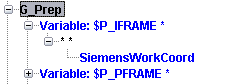
<!-- See Also — DEF Frame in the "Notes about the Siemens 840D Def command" in the Notes about Special Topics section in the Vericut Help Library.
- Optional Override Text word DWO_ON can be applied when a Dynamic Work Offset is required.
SiemensWorkCoordIndex
-
Function — WORK OFFSETS
-
Status — ACTIVE
-
Input —
- Text: Not Used
- Value: Index value into the Work Offset Table
-
Comment — Added V6.2
-
Input —
- Text: Not Used
- Value: Index value into the Work Offset Table
This macro is used to add , or modify, an entry in the Work Offsets table (ref. Work Offsets table, in the Tables for Processing G-Codes section, in the Vericut Help Library) when any Frame of $P_UIFR array is created, or modified. The index of $P_UIFR array element, is added to the macro value argument, to determine the index into Work Offset table where the new entry is to be added, or the existing entry that is to be modified.
See Also — DEF Frame in the "Notes about the Siemens 840D Def command" in the Notes about Special Topics section in the Vericut Help Library.
SiemensWPPartSide
-
Function — MISCELLANEOUS
-
Status — ACTIVE
-
Input —
- Text: Not Used
- Value: 0 = Off (Default)
-
Comment — Added V7.2.3
-
Input —
- Text: Not Used
- Value: 0 = Off (Default)
Any other value = On (the Part Side) This macro is used to resolve the direction of table rotation in the Working Plane logic for a very specific circumstance, when the tool vector is perpendicular to the table. In this case the Working Plane logic uses the direction of the X or Y axis to orient the table but on some machines the Siemens 840D control needs additional confirmation that part is on the table and the direction should be reversed relative to the tool. The use of this macro does not affect the regular Ijk2Abc logic.
SiemensXToolOffsetCompName
-
Function — TOOL OFFSETS
-
Status — ACTIVE
-
Input —
- Text: AXIS
- Value: Not Used
Specifies the name of the AXIS to which the "X tool offset" is applied. From the AXIS, we will get the corresponding component.
See Also — SiemensYToolOffsetCompName and SiemensZToolOffsetCompName
SiemensYToolOffsetCompName
-
Function — TOOL OFFSETS
-
Status — ACTIVE
-
Input —
- Text: AXIS
- Value: Not Used
Specifies the name of the AXIS to which the "Y tool offset" is applied. From the AXIS, we will get the corresponding component.
See Also — SiemensXToolOffsetCompName and SiemensZToolOffsetCompName
SiemensZToolOffsetCompName
-
Function — TOOL OFFSETS
-
Status — ACTIVE
-
Input —
- Text: AXIS
- Value: Not Used
Specifies the name of the AXIS to which the "Z tool offset" is applied. From the AXIS, we will get the corresponding component.
See Also — SiemensXToolOffsetCompName and SiemensYToolOffsetCompName
SimpleForLoop
-
Function — BRANCHING
-
Status — ACTIVE
-
Input —
- Value: Loop count
This command is used to process a simple "for" loop of the form:
-
LOOP number
-
...
-
NEXT
-
Or of the form (using open/close markers):The loop may also be in this form, where {} defines the beginning (OpenBlock) and ending (CloseBlock) of the block. NOTE: The characters represent the beginning/ending of a block be different on different control.
-
LOOP number
-
{
-
…
-
}
-
For this type of command, LOOP should call SimpleForLoop, and NEXT should call ForEndLoop.
-
If the optional text argument “REQUIRED” is specified, it means the beginning and ending of the loop must be specified with the calls to OpenBlock/CloseBlock
SkipWordIsOptimizable
-
Function — OPTIMIZATION
-
Status — ACTIVE
-
Input —
- Text: Not Used
- Value: 0 = blocks containing a SKIP character are not optimizable
-
0 = blocks containing a SKIP character are not optimizable
- Any other value = the SKIP character is optimizable (Default)
This macro is used to control when a "SKIP" word is optimizable (e.g. "$"). Calling this macro with a value of "0", indicates that blocks containing a SKIP character are not optimizable. Passing any non-zero value indicates the SKIP character is optimizable. Optimizable is the default condition for SKIP characters.
SpecialRotoTrans
-
Function — MISCELLANEOUS
-
Status — SPECIAL
-
Input —
- Text: Name of file to be read
- Value: Not Used
This macro is passed the name of the rototrans.txt file. It will read the specified file and set the G54 offset and the rotation matrix.
Note — This macro requires the rototrans.txt file to be in the exact syntax as defined below. The rototrans.txt program will look like the following:
-
$P_UIFR[1,X,TR]= 2.25
-
$P_UIFR[1,Y,TR]= 1.32
-
$P_UIFR[1,Z,TR]= 5.78
-
G54
-
ROT Z= 1.23
-
AROT X= 0.12
-
AROT Z= 0.92
SpecialRotoTransComp
-
Function — MISCELLANEOUS
-
Status — SPECIAL
-
Input —
- Text: Component name
- Value: Not Used
This command will move and rotate the specified component. The initial position is being defined by the Ball1 CSYS. The final position is being defined by the current G54 offset and the current rotation matrix.
SpindleChanger
-
Function — MISCELLANEOUS
-
Status — SPECIAL
-
Input —
- Text: Not Used
- Value: Not Used
Unloads the current spindle (if one exists), and loads the spindle specified with the SpindleValue macro. This macro is a MasterCenter specific macro.
SpindleMotionCCW
-
Function — FEEDS & SPEEDS
-
Status — ACTIVE
-
Input —
- Text: Not Used
- Value: Not Used
If the spindle speed was set, outputs the APT "SPINDL/%n,CCLW" statement. Otherwise, the APT "SPINDL/ON" statement is output. The SpindleMotionCCW macro takes into consideration part side/tool side, and the settings of Disable Auto Direction and Reverse Direction on the Modeling window: Component Attributes tab (ref. Modeling window: Component Attributes tab in the Vericut Help section, in the Vericut Help Library), when determining which direction is CCW. If the spindle component is on the part side, the spindle direction will be reversed.
This macro is equivalent to calling macro ActiveSpindleDir with Override Text = CCW, and macro ActiveSpindleOnOff with Override Value = 1.
Notes — 1. The SpindleMotionCCW macro should not be used when building new controls. Macro ActiveSpindleDir should be used instead. 2. This macro now applies to the active spindle component. For compatibility reasons, if the system is currently in "milling" mode (set by default, by macro VC_ModeMilling, or by macro VC_ModeMillingComp), then macro ActiveSpindleActiveTool will be automatically called to set the active spindle component. This macro should be replaced by the new ActiveSpindle... macros.
See "Notes about spindle configuration in V6" in the Notes about Special Topics section, in the Vericut Help Library, for additional information.
SpindleMotionCW
-
Function — FEEDS & SPEEDS
-
Status — ACTIVE
-
Input —
- Text: Not Used
- Value: Not Used
If the spindle speed was set, this macro outputs the "SPINDL/%n,CLW" statement. Otherwise, the APT "SPINDL/ON" statement is output. The SpindleMotionCW macro takes into consideration part side/tool side, and the settings of Disable Auto Direction and Reverse Direction on the Modeling window: Component Attributes tab (ref. Modeling window: Component Attributes tab in the Vericut Help section, in the Vericut Help Library), when determining which direction is CW. If the spindle component is on the part side, the spindle direction will be reversed.
This macro is equivalent to calling ActiveSpindleDir with Override Text = CW, and ActiveSpindleOnOff with Override Value = 1.
Notes — 1. The SpindleMotionCW macro should not be used when building new controls. Macro ActiveSpindleDir should be used instead. 2. This macro now applies to the active spindle component. For compatibility reasons, if the system is currently in "milling" mode (set by default, by macro VC_ModeMilling, or by macro VC_ModeMillingComp), then macro ActiveSpindleActiveTool will be automatically called to set the active spindle component. This macro should be replaced by the new ActiveSpindle... macros.
See "Notes about spindle configuration in V6" in the Notes about Special Topics section, in the Vericut Help Library, for additional information.
SpindleMotionOff
-
Function — FEEDS & SPEEDS
-
Status — ACTIVE
-
Input —
- Text: Not Used
- Value: Not Used
This macro outputs the APT "SPINDL/OFF" statement. This macro is equivalent to calling ActiveSpindleOnOff with Override Value = 0.
Note — This macro now applies to the active spindle component. For compatibility reasons, if the system is currently in "milling" mode (set by default, by macro VC_ModeMilling, or by macro VC_ModeMillingComp), then macro ActiveSpindleActiveTool will be automatically called to set the active spindle component. This macro should be replaced by the new ActiveSpindle... macros. See "Notes about spindle configuration in V6" in the Notes about Special Topics section, in the Vericut Help Library, for additional information.
SpindleOrient
-
Function — MISCELLANEOUS
-
Status — ACTIVE
-
Input —
- Text: Not Used
- Value: Spindle Axis position
-
Comment — Added V7.2
-
Input —
- Text: Not Used
- Value: Spindle Axis position
This macro will turn off, and then orient the Spindle to the specified Value. By default, the Spindle being modified will be the active Spindle. But, if this is a Siemens job and SiemensSpindleCompMapping was called, this macro will look for an entry that matches the current word that caused this macro to be executed. If an entry is found, the corresponding Spindle will be used. This is independent of what Spindle is currently active. See example below.
After the Spindle component has been identified, one of two things will happen:
- If the Spindle component is a Rotary component, the Spindle will be turned off and the corresponding AxisMotion command will be executed. For example: CAxisMotion
- If the Spindle component is not a Rotary component, then the following will happen:
By default, the motion will be calculated based on Absolute/Shortest distance.
-
If the value was set using the IncrementalValue function, treat the value as incremental.
-
If the value was set using a Siemens ACP, ACN, or DC command, the value will be adjusted accordingly.
-
Turn off the Spindle
-
If the distance is 0.0, return;
-
Move the Spindle
-
By default, set the time for the motion to be .001. If the minimum speed attribute was set for the Spindle, calculate the time based off the distance to move and the minimum speed.
-
This motion will be independent of any other motion that occurs on the current block. This means that if “After Motion” is not set, then the spindle orient motion will occur first, and then any other motion on the block will occur.
Example —
The following is an example of this macro being using with SiemensSpindleCompMapping
SiemensSpindleCompMapping OT=SPOS Spindle1 SP2 SP3
Assume SPOS calls SpindleOrient
-
SPOS[0] will stop and orient the Active Spindle
-
SPOS[1] will stop and orient Spindle1
-
SPOS[2] will stop and orient SP2
-
SPOS[3] will stop and orient SP3
See Also — Functions SiemensACP, SiemensACN, and SiemensDC to control the direction in which the Spindle is oriented.
Note — The active spindle must be a component of type Spindle or a Rotary component that can be used as a Spindle. If this is a Part side spindle, it is highly recommended that the component is a Rotary component.
SpindleOrientLocal
-
Function — MISCELLANEOUS
-
Status — ACTIVE
-
Input —
- Text: Not Used
- Value: Angle
-
Comment — Added in V8.1
-
Input —
- Text: Not Used
- Value: Angle
This macro behaves like SpindleOrient, but will rotate the spindle to orient it to the specified value relative to the local coordinate system. The macro calculates the angle necessary to rotate the spindle to align with the local coordinate system. It then adds this to the provided input angle before calling SpindleOrient.
Note — If the machine is built such that the orientation of the spindle is not aligned with the Machine axis, the result of the command might not be what is desired.
SpindleSpeed
-
Function — FEEDS & SPEEDS
-
Status — ACTIVE
-
Input —
- Text: Not Used
- Value: Spindle Speed
Sets the spindle speed to the input value, outputs a "SPINDL" command, updates the Status window to have the specified spindle speed, and sets the spindle mode to RPM. This macro is equivalent to calling macros RPMMode and ActiveSpindleSpeed. See "Notes about spindle configuration in V6" in the Notes about Special Topics section, in the Vericut Help Library, for additional information.
SpindleSpeedCheckOnOff
-
Function — FEEDS & SPEEDS
-
Status — Active
-
Input —
- Text: Not Used
- Value: 2 = ON for stock or tool spindles, 1 = ON tool spindles only, anything else = OFF (default)
-
Comment — Added V7.2
-
Input —
- Text: Not Used
- Value: 2 = ON for stock or tool spindles, 1 = ON tool spindles only, anything else = OFF (default)
This macro expects 1 argument, the value of 0, 1, or 2 If the value is 2 the flag is set to check Spindle Speed for all switched-on spindles, tool or stock. If the value is 1 the flag is set to check Spindle Speed for all switched-on tool spindles. If the value is 0 the flag is reset, and Spindle Speed is not checked .
SpindleValue
-
Function — ACTIVATION
-
Status — SPECIAL
-
Input —
- Text: Not Used
- Value: Tool Index number
-
Comment — This macro should only be used with with macro SpindleChanger.
-
Input —
- Text: Not Used
- Value: Tool Index number
This macro is used to set the spindle value which is to be loaded.
See Also — ActivateToolSubsystem
SpiralMotionOnOff
-
Function — MISCELLANEOUS
-
Status — ACTIVE
-
Input —
- Text: ON = turn on the special logic.
- Value: Not Used
-
Comment — Added V6.2
-
Input —
- Text: ON = turn on the special logic.
- Value: Not Used
This macro turns On/Off a special case logic to process spiral motions with greater refinement, speed and smoothness. This macro would most commonly be used used by grinder applications where a high level of accuracy and refinement is required.
StopOptional
-
Function — MISCELLANEOUS
-
Status — ACTIVE
-
Input —
- Text: Optional value: REPORT
- Value: Not Used
If Tool Change By is set to "List" (ref. NC Program window in the Vericut Help section, in the Vericut Help Library.), and List Tool Change By is set to "Prog. Stop" (ref. Tool Change List window in the Vericut Help section, in the Vericut Help Library), then this macro will cause a tool change to occur. The tool change will be based off the tool list.
If Stop At is set to "Optional Stop" (ref. Motion window in the Vericut Help section, in the Vericut Help Library), this macro will cause processing to stop.
If the Override Text value = REPORT, then the macro will ONLY be executed during the scan/report pass to get information needed to calculate tolerance, to build tool list, and to generate reports. The macro will not, however, be executed during the run pass, which means no tool will actually be loaded. This option will typically be used if a subroutine is called to execute the tool change. It would be called in addition to the tool change subroutine.
StopProgram
-
Function — MISCELLANEOUS
-
Status — ACTIVE
-
Input —
- Text: Optional value: REPORT
- Value: Not Used
If Tool Change By is set to "List" (ref. NC Program window in the Vericut Help section, in the Vericut Help Library.), and List Tool Change By is set to "Prog. Stop" (ref. Tool Change List window in the Vericut Help section, in the Vericut Help Library), then this macro will cause a tool change to occur. The tool change will be based off the tool list.
If Stop At is set to "Program Stop" (ref. Motion window in the Vericut Help section, in the Vericut Help Library), this macro will cause processing to stop.
If the Override Text value = REPORT, then the macro will ONLY be executed during the scan/report pass to get information needed to calculate tolerance, to build tool list, and to generate reports. The macro will not, however, be executed during the run pass, which means no tool will actually be loaded. This option will typically be used if a subroutine is called to execute the tool change. It would be called in addition to the tool change subroutine.
StopUnconditional
-
Function — MISCELLANEOUS
-
Status — ACTIVE
-
Input —
- Text: Not Used
- Value: Not Used
This macro will cause processing to stop. If this macro is invoked within an "IF" condition, a check is done to determine that the "IF condition" is true before processing is stopped. The calling of this macro will not be considered as a possible tool change event.
StringMatchCase
-
Function — MISCELLANEOUS
-
Status — ACTIVE
-
Input —
- Text: Not Used
- Value: 0 = String compare without letter case consideration (Default)
-
Comment — Added V7.2.3
-
Input —
- Text: Not Used
- Value:
- 0 = String compare without letter case consideration (Default)
- 1 = String compare with letter case consideration
This macro is used to set the condition for string compare operations. When Override Value = 0 the string compare operations (Equal or Not Equal) are done regardless letter case (ABc is equal abC). This is the default condition. With Override Value = 1 strings must match exactly using letter case. This macro is necessary for Siemens 840D string operations used in some cycles.
SubEndingSeq
-
Function — SUBROUTINES
-
Status — ACTIVE
-
Input —
- Text: Not Used
- Value: Ending Sequence number
This macro defines the ending sequence number for the current subroutine being called. The value is non-modal. When the sequence number is reached within the subroutine, a return from the subroutine is executed.
See Also — SubStartingSeq
SubEofErrorOnOff
-
Function — SUBROUTINES
-
Status — ACTIVE
-
Input —
- Text: Not used
- Value: 0 = No ERROR (default), 1 = ERROR, 2 = ERROR and STOP
This macro determines if an error should be given if we come to the end of a file without processing some form of EndSub or ReturnFromSub.
SubroutineBlock
-
Function — SUBROUTINES
-
Status — ACTIVE
-
Input —
- Text: Possible subroutine name
- Value: Possible sequence number
This macro defines the start of a subroutine. This macro is similar to SubroutineSequence, except if the start of subroutine line was reached without being called, it will immediately jump to the end of the subroutine.
Note — Use this macro to support the Acramatic DFS (define subroutine) command.
SubroutineCreatesVariableScope
-
Function — SUBROUTINES
-
Status — ACTIVE
-
Input —
- Text: Not used
- Value: 0 = NO, 1 = YES (default)
This macro determines if a new variable scope should be created when a subroutine is called. This macro is non-modal, meaning it only apply to this block. This macro needs to be called before calling the corresponding subroutine. If a new variable scope is not created, then any new variables created within this subroutine will be associated with its parent subroutine (actually, the first parent that did create a variable scope).
SubroutineName
-
Function — SUBROUTINES
-
Status — ACTIVE
-
Input —
- Text: Possible subroutine name
- Value: Possible subroutine number
This macro is used to set the subroutine name that is then used by the CallNCMacro macro, or the CallSub macro.
SubroutineNameNumeric
-
Function — SUBROUTINES
-
Status — ACTIVE
-
Input —
- Text: Not Used
- Value: Subroutine number
-
Comment — Added V6.2
-
Input —
- Text: Not Used
- Value: Subroutine number
This macro is used to set the subroutine name that is then used by the CallNCMacro macro, or the CallSub macro. This macro also sets the subroutine name type to be NUMERIC.
This allows the following configuration, assuming the Type of Subroutine Name is set to Numeric:
-
P * M 98 SubroutineName
-
< * M 98 SubroutineNameText
-
< * (G 65 66 66.1) SubroutineNameText
-
M 98 P * CallSub
-
M 98 < * CallSub
-
G 65 CallNCMacro
-
G 66 CallNCMacroMotion
-
G 66.1 CallNCMacroBlock
Note — The name is now always the argument for the action defined with the M98, G65, G66, or G66.1. When the Name is set, the subroutine name type is also set, which is then used by the CallSub, CallNCMacro, CallNCmacroMotion), and CallNCMacroBlock macros.
- See "Notes about Subroutine Names – Numeric vs Text" in the Notes about Special Topics section, in the Vericut Help Library for additional information.
SubroutineNameText
-
Function — SUBROUTINES
-
Status — ACTIVE
-
Input —
- Text: Subroutine name
- Value: Not Used
-
Comment — Added V6.2
-
Input —
- Text: Subroutine name
- Value: Not Used
Use the SubroutineNameText macro to set the subroutine name that is used by the CallNCMacro and CallSub macros. This macro also sets the subroutine name type to be TEXT. See "Notes about Subroutine Names – Numeric vs Text" in the Notes about Special Topics section, in the Vericut Help Library for additional information.
SubroutineOrderLogic
-
Function — SUBROUTINES
-
Status — ACTIVE
-
Input —
- Text: Not Used
- Value: 1 = Uses existing logic (default) , 2=Do not include the current file in the search list
-
Comment — Added V9.5x
-
Input —
- Text: Not Used
- Value: 1 = Uses existing logic (default) , 2=Do not include the current file in the search list
Ideally, all subroutine names should be unique. If they are unique, the order we look for the subroutine does not matter. But, it is known that we look for a subroutine in the project subroutine files first, then the machine subroutine files, and then the control subroutine files. This means that you can override a control subroutine by putting in a machine subroutine by the same name. However, logic was added to look in the current subroutine file first. This breaks the order described above.
Calling this macro with OV=2, will remove the current file from the search list. When looking for a subroutine, it will search in the following order:
-
1. Init files
-
2. Main program
-
3. Project subroutine files
-
4. Machine subroutine files
-
5. Control subroutine files
Note — This macro will have no effect if all subroutine names are unique (which should be the normal case).
SubroutineParsingOptions
-
Function — SUBROUTINES
-
Status — ACTIVE
-
Input —
- Text: Not Used
- Value: 1 or 2, see description below.
-
Comment — Added 7.1
-
Input —
- Text: Not Used
- Value: 1 or 2, see description below.
This macro enables the the use of special subroutine parsing options/logic. This macro would typically be called during the "Start of Processing" event. Because of the extra checks that are made, enabling the special parsing logic will slow down the parsing process. It is therefore recommended that this macro only be used when it is known that it is required based on the subroutine names that are used, and the control that is being used.
Based on the input value, the following options are supported:
-
- = If the Word "SubroutineName" exists, then for every word found during parsing, if the next character is an alphabetic character, check if the entire string up to the next white space matches an existing subroutine name. (Default)
-
- = If the Word "SubroutineName" exists, then for every word found during parsing, check if the entire string up to the next white space matches an existing subroutine name. This means that for the line X1Y2Z3, Vericut will check if "X1Y2Z3", "Y2Z3", and "Z3" are existing subroutine names.
SubroutineSequence
-
Function — SUBROUTINES
-
Status — ACTIVE
-
Input —
- Text: Subroutine name
- Value: Sequence number (only used in very rare occasions)
Similar to the Sequence macro for jobs defined as a single pass. On multi-pass jobs, the current location within the file is marked during the first pass as the beginning of a subroutine.
SubroutineSequenceEnd
-
Function — SUBROUTINES
-
Status — ACTIVE
-
Input —
- Text: Subroutine name
- Value: Sequence number (only used in very rare occasions)
This routine is identical to SubroutineSequence except it also marks the previous subroutine, if any, as ended.
Note — A new routine was created to avoid causing problems with existing customers where SubroutineSequence was being called for something other than the start of a subroutine.
SubSpindleTransform
-
Function — MISCELLANEOUS
-
Status — OBSOLETE
-
Input —
- Text: None
- Value: None
-
Comment — This macro is no longer supported.
SubStartingSeq
-
Function — SUBROUTINES
-
Status — ACTIVE
-
Input —
- Text: Not Used
- Value: Starting sequence number
Use the SubStartingSeq macro to set the starting sequence number for a call into a subroutine.
See Also — SubEndingSeq
SubsystemActivateTool
-
Function — ACTIVATION
-
Status — ALTERNATE
-
Input —
- Text: Not Used
- Value: Not Used
-
Comment — Use ActivateToolSubsystem
-
Input —
- Text: Not Used
- Value: Not Used
Activates the tool associated with the current subsystem. This command sets the active tool based on the first tool it finds given the current subsystem. This command is integrated with the Sync logic. This command should not be used if more then 1 tool could exist for a given subsystem.
SurfaceSpeed
-
Function — FEEDS & SPEEDS
-
Status — ACTIVE
-
Input —
- Text: Not Used
- Value: Surface speed
Use the SurfaceSpeed macro to specify that the part spindle RPM's will be set such that the surface speed of the tool will remain constant at the given rate. The rate is specified as Feet Per Minute or Meters Per Minute.
SuspendCutting
-
Function — MISCELLANEOUS
-
Status — ACTIVE
-
Input —
- Text: Not Used
- Value: Not Used
The SuspendCutting macro stops the normal processing of the current block. This means that cutting and positional updates will not occur.
SyncCode
-
Function — SYNC
-
Status — ACTIVE
-
Input —
- Text: Not Used
- Value: Sync code
-
Comment — Added V6.0
-
Input —
- Text: Not Used
- Value: Sync code
The SyncCode macro sets the current Sync value. This value is used by the SyncId macro to cause the current head (also known as subsystem, program, system, or channel) to wait until the specified head reaches the corresponding Sync value. This value is also used by the SyncIds macro to cause the current head (also known as subsystem, program, system, or channel) to wait until the specified heads (specified as an index value; 1 to 9) reach the corresponding Sync value. Previous macros like SyncMacro and SyncValue were based on a 2 sync head only scenario. These macros caused a wait until the "other" head reaches a corresponding spot.
SyncCodeAlpha
-
Function — SYNC
-
Status — ACTIVE
-
Input —
- Text: SyncCode
- Value: Not used
-
Comment — Added V8.0
-
Input —
- Text: SyncCode
- Value: Not used
The SyncCodeAlpha macro sets the current alpha-numeric Sync value. This value is used by alpha Sync macros. This macro is similar to the macro SyncCode, which uses a numeric Sync value.
SyncId
-
Function — SYNC
-
Status — ACTIVE
-
Input —
- Text: Not Used
- Value: Channel number
-
Comment — Added V6.0
-
Input —
- Text: Not Used
- Value: Channel number
Causes the current head (also known as subsystem, program, system, or channel) to wait until the specified head (specified as a value; 1 to n) reaches the corresponding Sync value. The Sync value needs to be set prior to this call. This Sync value is set by calling the SyncCode macro.
SyncIds
-
Function — SYNC
-
Status — ACTIVE
-
Input —
- Text: Not Used
- Value: Channel numbers
-
Comment — Added V6.0.1
-
Input —
- Text: Not Used
- Value: Channel numbers
Causes the current head (also known as subsystem, program, system, or channel) to wait until the specified heads (specified as an index value; 1 to 9) reaches the corresponding Sync value. This macro is called with a list of Sync IDs for its numeric value. For example, 123 would sync heads 1, 2, and 3. Any Sync ID corresponding to itself would be ignored. The Sync value needs to be set prior to this call. This Sync value is set by calling the SyncCode macro.
SyncIdsBinaryAlpha
-
Function — SYNC
-
Status — ACTIVE
-
Input —
- Text: Not Used
- Value: Each bit of the value corresponds to a channel. The one’s bit corresponds
-
Comment — Added V8.0
-
Input —
- Text: Not Used
- Value: Each bit of the value corresponds to a channel. The one’s bit corresponds
to the first channel. If the bit is set, we are syncing with that channel. Causes the current head (also known as subsystem, program, system, or channel) to wait until the specified heads reaches the corresponding Sync value. The input value is bit encode to represent each head. For example: a value of 12 would correspond to the 3rd and 4th heads. Any head corresponding to itself would be ignored. The Sync value needs to be set prior to this call. This Sync value is set by calling the SyncCodeAlpha macro.
SyncMacro
-
Function — SYNC
-
Status — ACTIVE
-
Input —
- Text: Not Used
- Value: Not Used
SyncMacro causes the active head to wait at the current location until the other head reaches the corresponding sync location.
SyncMismatchHandling
-
Function — SYNC
-
Status — ACTIVE
-
Input —
- Text: Not Used
- Value: 0 = Head with lower sync value continues on (Default)
-
Comment — Added V6.0
-
Input —
- Text: Not Used
- Value:
- 0 = Head with lower sync value continues on (Default)
- 1 = Produce an error message and stop
This macro determines how a Sync value mismatch should be handled. The default is to have the head with the lower value continue on.
Notes — 1. The sync value can be set with the following macros: SyncId, SyncIds, SyncValue, and SyncMacro. 2. SyncCode is used to set the sync value which is then used by SyncID and SyncIds.
SyncNoWaitOption
-
Function — SYNC
-
Status — ACTIVE
-
Input —
- Text: Not Used
- Value: 1 = Process all sync codes in order
-
Comment — s: added V8.0
-
Input —
- Text: Not Used
- Value:
- 1 = Process all sync codes in order
- 2 = A matching entry for a NO_WAIT sync code might or might not exist.
If you are using the NO_WAIT option for sync codes (See SyncWaitOnOff), then it possible for Channel 1 to say I am at position 100, then 200, then 300 before the corresponding channel reaches 100. This macro specifies whether the correspond channel must respond in order. For example: If “1 is specified, the corresponding channel must respond with 100, then 200, then 300. If “2” is specified, it would be valid for the corresponding channel to not have a 100 or 200, and have its first sync code to be a 300.
SyncTransfer
-
Function — SYNC
-
Status — ACTIVE
-
Input —
- Text: Not Used
- Value: Channel number
This macro is used to specify the channel number for the CSS controlling channel. Enter the channel number in the Override Value field.
SyncValue
-
Function — SYNC
-
Status — ACTIVE
-
Input —
- Text: Optional argument: ALL
- Value: Sync code value
The SyncValue macro sets the current Sync value. This will cause the current head to wait until the other processes a Sync value that is greater than, or equal to, the specified value. If a text value of "ALL" is passed, the current input channel will sync with all other input channels.
SyncWaitOnOff
-
Function — SYNC
-
Status — ACTIVE
-
Input —
- Text: Not used
- Value: 0 = no wait, 1 = wait (default)
-
Comment — Added V8.0
-
Input —
- Text: Not used
- Value: 0 = no wait, 1 = wait (default)
The Sync macros typically causes the current channel to wait until the other specified channels to reach the same Sync point. This macro gives the capability to notify the specified channels that you have arrived, but not wait for the other channels. All Sync macros have been enhanced to support this feature.
Note — If channel 1 gives a NO WAIT Sync command specifying channel 2, it is expected that channel 2 will also get a Sync command with the same Sync Value. If a mismatch occurs, an error may be printed. See SyncMismatchHandling.
SyntaxErrorOption
-
Function — MISCELLANEOUS
-
Status — ACTIVE
-
Input —
- Text: Not Used
- Value: 0: Cancels detection and output of error messages controlled by this macro (Default)
-
Comment — Added V7.0.2
-
Input —
- Text: Not Used
- Value:
- 0: Cancels detection and output of error messages controlled by this macro (Default)
- 1: Activates the detection and output of the error message in cases where an assignment is detected without an assign token.
This macro allows controlling detection and output of error messages during the parsing process of an input mcd code. This feature is designed for specific controls where the NC code is not conventional.
This macro can be expanded in the future to control other types of errors detected during the parsing process.
See also — SetPreProcessorType
TableIndex
-
Function — TABLES
-
Status — ACTIVE
-
Input —
- Text: Not Used
- Value: Table Index
Use to set the index/register number of the table entry to be modified. Used with SetTableValues and SetTableCoord. Default is 1. Use the Override Value field to specify the table index number. TableIndex must be called before calling SetTableValues.
TableSubRegisterValue
-
Function — TABLES
-
Status — ACTIVE
-
Input —
- Text: Not Used
- Value: Sub Register value
-
Comment — Added V6.2
-
Input —
- Text: Not Used
- Value: Sub Register value
Use to set the SubRegister value that is used with Tables. Currently, this is only used with the Work Offset tables. The default is 1. This value is modal. This value will be used with the following macros:
TableValues
-
Function — TABLES
-
Status — ACTIVE
-
Input —
- Text: Not Used
- Value: Table value
This macro can be called up to 12 times to store 12 values. For a normal table the order of the values will be: X,Y,Z,A,B,C,U,V,W,A2,B2,C2. This macro is used with the macro SetTableValues. TableValues must be called before calling SetTableValues.
TangentialAngle
-
Function — TANGENTIAL APPROACH AND EXIT
-
Status — ACTIVE
-
Input —
- Text: Not Used
- Value: Angle
-
Comment — Added V6.2
-
Input —
- Text: Not Used
- Value: Angle
This macro defines the angle for a line/circle movement and must be used for a "CCA" word.
TangentialCapture
-
Function — Tangential Approach and Exit
-
Status — ACTIVE
-
Input —
- Text: Not Used
- Value: - 0 = Capture off
-
Comment — Added V6.2
-
Input —
- Text: Not Used
- Value:
- 0 = Capture off
- 1 = Capture on
This macro turns off/on the action record storing capability needed for the Tangential logic. This macro must be called after the ConversionInit macro and before any other Tangential macros are called. It is recommended that this macro be called from the Start of Processing event.
TangentialControlType
-
Function — TANGENTIAL APPROACH AND EXIT
-
Status — ACTIVE
-
Input —
- Text: Not Used
- Value: - 0 = Generic control type (default)
-
Comment — Added V7.1
-
Input —
- Text: Not Used
- Value:
- 0 = Generic control type (default)
- 1 = Siemens control
This macro sets the control type. This macro must be called after the ConversionInit macro. It is recommended that this macro be called from the Start of Processing event.
TangentialInit
-
Function — TANGENTIAL APPROACH AND EXIT
-
Status — ACTIVE
-
Input —
- Text: Not Used
- Value: - 0 = Approach (Default)
-
Comment — Added V6.2
-
Input —
- Text: Not Used
- Value:
- 0 = Approach (Default)
- 1 = Exit
- This macro defines the type of tangential move (approach or exit) to be generated. The default is 0 (approach).
TangentialMethod
-
Function — TANGENTIAL APPROACH AND EXIT
-
Status — ACTIVE
-
Input —
- Text: Not Used
- Value: - 0 = Line and Circle (Default)
-
Comment — Added V6.2
-
Input —
- Text: Not Used
- Value:
- 0 = Line and Circle (Default)
- 1 = Quarter Circle
- 2 = Semicircle
- 3 = Helix for feeding
- 4 = Parallel to contour
- 5 = Vertical
This macro defines the tangential method. The default is 0 (line and circle).
TangentialMovement
-
Function — TANGENTIAL APPROACH AND EXIT
-
Status — ACTIVE
-
Input —
- Text: Not Used
- Value: - 0 = Rapid
-
Comment — Added V6.2
-
Input —
- Text: Not Used
- Value:
- 0 = Rapid
- 1 = Feed
This macro defines the movement, rapid or linear, for the first movement of a two movement tangential case. The second movement is always a feed.
TangentialPolar
-
Function — TANGENTIAL APPROACH AND EXIT
-
Status — ACTIVE
-
Input —
- Text: Not Used
- Value: - 0 = the contour point is in Cartesian coordinates
-
Comment — Added V6.2
-
Input —
- Text: Not Used
- Value:
- 0 = the contour point is in Cartesian coordinates
- 1 = the contour point is in Polar coordinates
This macro is used to specify whether the contour point, in the APPR statement, is in Cartesian or Polar coordinates. Use the Tangential Polar macro with an Override Value of "0" to indicate that the contour point is in Cartesian coordinates. Use the Tangential Polar macro with an Override Value of "1" to indicate that the contour point is in Polar coordinates, and therefore needs be converted to Cartesian coordinates. The TangentialPolar macro must be called using a value of "1" for the words PLT, PLN, PCT and PLCT.
TangentialRadius
-
Function — TANGENTIAL APPROACH AND EXIT
-
Status — ACTIVE
-
Input —
- Text: Not Used
- Value: Radius
-
Comment — Added V6.2
-
Input —
- Text: Not Used
- Value: Radius
This macro defines the radius of the circle for tangential method [0,1,2,3] and one half length of segment for tangential method [4,5].
TangentialStartZ
-
Function — TANGENTIAL APPROACH AND EXIT
-
Status — ACTIVE
-
Input —
- Text: Not Used
- Value: Height of the start point
-
Comment — Added V6.2
-
Input —
- Text: Not Used
- Value: Height of the start point
This macro defines the height of the start point of the approach movement.
TapeBulkFactor
-
Function — TAPE LAYING
-
Status — ACTIVE
-
Input —
- Text: Not Used
- Value: Tape bulk factor percentage
This macro sets the default tape bulk factor percentage. For example, to set the bulk factor to 30%, set Value = 30.
TapeCacheAddSubDecimalTows
-
Function — TAPE LAYING
-
Status — ACTIVE
-
Input —
- Text: 1 = ADD, anything else = SUBTRACT
- Value: Additional Tows to be turned on/off (decimal number). Each bit corresponds to a tow.
-
Comment — Added V9.4.x
-
Input —
- Text: 1 = ADD, anything else = SUBTRACT
- Value: Additional Tows to be turned on/off (decimal number). Each bit corresponds to a tow.
Before laying the tape, a list is given which defines the point at which specific tows are to be turned on/off.
With this macro, the text argument defines whether we are adding or removing tows. NOTE: This is the additional tows to be added or removed. The value argument specifies which tows. Each binary bit that is on corresponds to that Tow being turned on/off. Therefore, a value of 1 turns on/off the first tow, and a value of 3 turns on/off the first two tows.
The Macro TapeCachePoint defines the distance along the course where these tows are to be turned on/off.
Note — TapeCachePoint must be called before calling TapeCacheAddSubDecimalTows.
TapeCacheAddSubHexTows
-
Function — TAPE LAYING
-
Status — ACTIVE
-
Input —
- Text: Hex string specifying which tows to add/subtract
- Value: 1=ADD, anything else = SUBTRACT
-
Comment — Added V7.3
-
Input —
- Text: Hex string specifying which tows to add/subtract
- Value: 1=ADD, anything else = SUBTRACT
This macro was written specifically for Spirit/Ingersoll machine. Before laying the tape, a list is given which defines the point at which specific tows are to be turned on. Macro TapeCachePoint defines the distance. This macro defines what additional tows to add (turn on), or which tows to subtract (turn off).
Each hexadecimal digit that is on corresponds to that Tow being turned on/off. Therefore, a value of 1 turns specifies the first tow. A value of “C0” specifies the 7th and 8th tow.
Additional logic has been added to support a “recovery point”. If a cache list exists, and if the cache point is before the first specified tow cache point, then this is a recovery point, then the specified tow value corresponds the all tows that are currently on, and this record is added to the head of the list.
TapeCacheLaneOff
-
Function — TAPE LAYING
-
Status — ACTIVE
-
Input —
- Text: offset distance in project units of lane extension. Negative value for late lane extension. Use “NO_RETRACT” to turn off tow but not retract lane
- Value: lane/roller number
-
Comment — Added V8.0
-
Input —
- Text: offset distance in project units of lane extension. Negative value for late lane extension. Use “NO_RETRACT” to turn off tow but not retract lane
- Value: lane/roller number
This macro causes the specified lane/roller to be turned off and retracted. The tow will always turn off at the point specified with the macro TapeCachePoint. The retraction of the lane/roller can be executed after this point with a negative number in the Text field. A value of zero will result in retraction of the lane occurring simultaneously with the tow cut. A positive distance value (early retraction) is not allowed. Overall actuation must be turned on first through TapeMoveRollersOnOff.
Note — Each tow might be offset in Y. The roller number is used as the Tool Index number, and an offset is calculated between the current component and the roller component with Tool Index 0. The distance specified with TapeCachePoint will be adjusted by this offset.
TapeCacheLaneOn
-
Function — TAPE LAYING
-
Status — ACTIVE
-
Input —
- Text: offset distance in project units of lane extension. Positive value for early lane extension.
- Value: lane/roller number
-
Comment — Added V8.0
-
Input —
- Text: offset distance in project units of lane extension. Positive value for early lane extension.
- Value: lane/roller number
This macro causes the specified lane/roller to be turned on and extended. The tow will always turn on at the point specified with the macro TapeCachePoint. The extension of the lane/roller can be executed prior to this point with a positive number in the Text field. A value of zero will result in extension of the lane occurring simultaneously with the tow add. A negative distance value (late extension) is not allowed. Overall actuation must be turned on first through TapeMoveRollersOnOff.
Note — Each tow might be offset in Y. The roller number is used as the Tool Index number, and an offset is calculated between the current component and the roller component with Tool Index 0. The distance specified with TapeCachePoint will be adjusted by this offset.
TapeCachePoint
-
Function — TAPE LAYING
-
Status — ACTIVE
-
Input —
- Text: Not Used
- Value: Distance
-
Comment — Added V6.1
-
Input —
- Text: Not Used
- Value: Distance
The TapeCache macros were written specifically for the Electroimpact (EI) tape formatted data. Before laying the tape, a list is given which defines the distance at which specific tows are to be turned on. Macro TapeCachePoint defines the distance. Macro TapeCacheTows specifies the tows that are to be turned on at this point.
TapeCacheRollerOff
-
Function — TAPE LAYING
-
Status — ACTIVE
-
Input —
- Text: Not used
- Value: Tow number. Valid range: 0-31
-
Comment — Added V7.4.2
-
Input —
- Text: Not used
- Value: Tow number. Valid range: 0-31
This macro marks that the specified tow is to be turned off at the point specified with the macro TapeCachePoint.
Note — Each tow might be offset in Y. The roller number is used as the Tool Index number, and an offset is calculated between the current component and the roller component with Tool Index 0. The distance specified with TapeCachePoint will be adjusted by this offset.
TapeCacheRollerOn
-
Function — TAPE LAYING
-
Status — ACTIVE
-
Input —
- Text: Not used
- Value: Tow number. Valid range: 0-31
-
Comment — Added V7.4.2
-
Input —
- Text: Not used
- Value: Tow number. Valid range: 0-31
This macro marks that the specified tow is to be turned on at the point specified with the macro TapeCachePoint.
Note — Each tow might be offset in Y. The roller number is used as the Tool Index number, and an offset is calculated between the current component and the roller component with Tool Index 0. The distance specified with TapeCachePoint will be adjusted by this offset.
TapeCacheTowOnOff
-
Function — TAPE LAYING
-
Status — ACTIVE
-
Input —
- Text: Tow_number Distance
- Value: 0 = Off, 1 = ON
-
Comment — Added V9.4.
-
Input —
- Text: Tow_number Distance
- Value: 0 = Off, 1 = ON
This macro specifies that a specific Tow should be turned on/off when the tape reaches a specified distance. When laying tape, the distance along the course needs to be set with TapeCourseTValue. The Tow number should be between 1 and the number of tows. This specifies the specific (one and only 1) tow that is being turned on/off. The Distance must be positive.
TapeCacheTowOnOff2
-
Function — TAPE LAYING
-
Status — ACTIVE
-
Input —
- Text: ON or OFF
- Value: tow number – in the range of 1 to 32
-
Comment — Added V9.5.1
-
Input —
- Text: ON or OFF
- Value: tow number – in the range of 1 to 32
This macro specifies that a specific Tow should be turned on/off when the tape reaches a specified distance. The distance must have been previously set with TapeCachePoint. When laying tape, the distance along the course needs to be set with TapeCourseTValue. The Tow number should be between 1 and the number of tows (max 32). This specifies the specific (one and only 1) tow that is being turned on/off.
TapeCacheTows
-
Function — TAPE LAYING
-
Status — ACTIVE
-
Input —
- Text: Optional argument: INV
- Value: Tows to be turned on. Each bit corresponds to a tow.
-
Comment — Added V6.1
-
Input —
- Text: Optional argument: INV
- Value: Tows to be turned on. Each bit corresponds to a tow.
The TapeCache... macros were written specifically for the Electroimpact (EI) tape formatted data. Before laying the tape, a list is given which defines the point at which specific tows are to be turned on. Macro TapeCachePoint defines the distance. Macro TapeCacheTows specifies the tows that are to be turned on at this point. Macro TapeCacheTows Each binary bit that is on corresponds to that Tow being turned on. Therefore, a value of 1 turns on the first tow on the right, and a value of 3 turns on the first two tows on the right. If the bits are in reverse order, use the text argument INV.
TapeCacheTows2
-
Function — TAPE LAYING
-
Status — ACTIVE
-
Input —
- Text: Series of tow on/off switches, followed by a distance
- Value: Not Used
-
Comment — Added V7.2.1
-
Input —
- Text: Series of tow on/off switches, followed by a distance
- Value: Not Used
The TapeCacheTows2 macro was written specifically for a TOWCMD on an ATK tape caching machine.
The text argument is in the form:
-
0000,0000,0000,0000,distance
-
Each of the first 16 0/1 values represents a tow’s on/off value. The “distance” argument is the distance along the path where these tows should be turned on/off.
TapeCacheTowsEvenOffset
-
Function — TAPE LAYING
-
Status — ACTIVE
-
Input —
- Text: Not used
- Value: offset valued (default = 65)
-
Comment — Added in V8.2
-
Input —
- Text: Not used
- Value: offset valued (default = 65)
This macro sets the odd offset, which is used by TapeCacheTowsOddEven. This offset corresponds to a distance along the course, from the current position, that the even tow information will apply.
TapeCacheTowsOddEven
-
Function — TAPE LAYING
-
Status — ACTIVE
-
Input —
- Text: Optional argument: INV
- Value: Tows to be turned on. Each bit corresponds to a tow.
-
Comment — Added in V8.2
-
Input —
- Text: Optional argument: INV
- Value: Tows to be turned on. Each bit corresponds to a tow.
This macro is used to specify which tows are on – Similar to TapeCacheTows.
For this macro, this applies to some point in the future. For odd tows, it is the odd offset distance from the current position. For even tows, it is an even offset distance from the current position. To set the odd/even offsets, call TapeCacheTowsEvenOffset and TapeCacheTowsOddOffset.
TapeCacheTowsOddOffset
-
Function — TAPE LAYING
-
Status — ACTIVE
-
Input —
- Text: Not used
- Value: offset valued (default = 75)
-
Comment — Added in V8.2
-
Input —
- Text: Not used
- Value: offset valued (default = 75)
This macro sets the odd offset, which is used by TapeCacheTowsOddEven. This offset corresponds to a distance along the course, from the current position, that the odd tow information will apply.
TapeCourseTValue
-
Function — TAPE LAYING
-
Status — ACTIVE
-
Input —
- Text: Not Used
- Value: T value
-
Comment — Added V7.0.1
-
Input —
- Text: Not Used
- Value: T value
This macro is used to define the course T Value, a parametric parameter that states how far along the course we are. This is typically used with the pre-definition of when tows are to be turned on and off.
TapeDensity
-
Function — TAPE LAYING
-
Status — ACTIVE
-
Input —
- Text: Not Used
- Value: Tape density, measured in inches/pound or mm/kg
-
Comment — Added V6.1
-
Input —
- Text: Not Used
- Value: Tape density, measured in inches/pound or mm/kg
Although density is usually specified in units of weight/volume, this macro is expecting the density to be specified in inches/pound (if the system units are inch), or mm/kg (if the system units are mm). This value is used to display statistics on the weight of the tape that has been laid. The default is 9552 in/lb. No unit conversion is made on this value. The input values should be based on system units.
TapeHead
-
Function — TAPE LAYING
-
Status — ACTIVE
-
Input —
- Text: Tape Head ID
- Value: If 0, reload all tows
-
Comment — Added V6.1
-
Input —
- Text: Tape Head ID
- Value: If 0, reload all tows
This macro causes the statistics to now be applied to the head specified in the text field. If this head has not previously been used, the head statistics will be initialized to default values.
Note — Make sure the default values are set prior to calling this macro.
TapeHeadOnOff
-
Function — TAPE LAYING
-
Status — ACTIVE
-
Input —
- Text: Not Used
- Value: 1 – On, Any other value = Off (Default)
-
Comment — Added V7.0.1
-
Input —
- Text: Not Used
- Value: 1 – On, Any other value = Off (Default)
Although this macro was originally written specifically for the Electroimpact (EI) tape formatted data, this is now also used with MTorres Wide Tape processing when the WTapeTurnOffWithCutOff feature is used.
TapeHeadService
-
Function — TAPE LAYING
-
Status — ACTIVE
-
Input —
- Text: Not Used
- Value: Not Used
-
Comment — Added V6.1
-
Input —
- Text: Not Used
- Value: Not Used
This macro causes the following statistics to be reset:
- The number of cuts on this head since the last service.
- The time since the last service (the time laying tape and traversing).
- The time laying tape since the last service.
Note —
- These statistics are kept on both the head and each tow. Both the head and tow statistics are reset by this command.
- This macro does not cause the tape to be reloaded. See TapeReloadTow and TapeReloadAllTows.
TapeInitialLength
-
Function — TAPE LAYING
-
Status — ACTIVE
-
Input —
- Text: Not Used
- Value: Tape length.
-
Comment — Added V6.1
-
Input —
- Text: Not Used
- Value: Tape length.
This macro sets the default tape length. It is used when the TapeHead macro is called for a new head, and when macro TapeReloadAllTows,or TapeReloadTow, is called. It is used to track how much tape is left, and to cause an error and stop if you run out of tape. Units are in either inches or mm. The default is 53712 inches (6 lb roll at 796 ft/lb).
TapeLayer
-
Function — TAPE LAYING
-
Status — OBSOLETE
-
Input —
- Text: Not Used
- Value: Tape layer
-
Comment — See TapeSetNewLayer
-
Input —
- Text: Not Used
- Value: Tape layer
This macro specifies the current tape layer.
TapeMarkerLength
-
Function — TAPE LAYING
-
Status — ACTIVE
-
Input —
- Text: Not Used
- Value: Maximum marker distance from the mandrel
-
Comment — Added V7.4.2
-
Input —
- Text: Not Used
- Value: Maximum marker distance from the mandrel
This macro is used to specify the maximum distance that the marker can be from the mandrel before marking stops.TapeMarkerOnOff.
TapeMarkerOnOff
-
Function — TAPE LAYING
-
Status — ACTIVE
-
Input —
- Text: Not Used
- Value: 0 = Off, 1 = On
-
Comment — Added V7.2.3
-
Input —
- Text: Not Used
- Value: 0 = Off, 1 = On
This macro turns the tape marker feature On and Off.
TapeMoveRollers
-
Function — TAPE LAYING
-
Status — ACTIVE
-
Input —
- Text: ALL, or an integer whose binary representation selects which rollers to move
- Value: Not Used
-
Comment — Added V8.0
-
Input —
- Text:
ALL, or an integer whose binary representation selects which rollers to move - Value: Not Used
- Text:
Moves the specified rollers on the current subsystem to their active positions. Supports composite machines with independently actuated rollers that can extend and retract.
Roller selection:
ALL— moves all rollers.- An integer value — interpreted in binary; each bit position corresponds to a roller by Tool Index.
Example — A Text value of 12 is binary 1100, which selects rollers with Tool Index 3 and 4.
Note — TapeMoveRollersOnOff must be active before calling this macro; if it is not, a warning is issued and no rollers are moved.
See also — TapeMoveRollersOnOff, TapeRollerContactPoints
TapeMoveRollersOnOff
-
Function — TAPE LAYING
-
Status — ACTIVE
-
Input —
- Text: Not used
- Value: 0 = OFF, anything else = ON
-
Comment — Added V8.0
-
Input —
- Text: Not used
- Value: 0 = OFF, anything else = ON
Turns on/off overall actuation ability of all roller(s) for a tape machine. Would typically be placed in the “Start of Processing” event as it is a machine ability. Must be turned on before roller actuation macros (TapeMoveRollers, TapeCacheLaneOn, TapeCacheLaneOff) can be called.
Machine/Tool Setup Requirements —
The code does a check to ensure that the tool (tape laying head) has a specific setup. If this check fails, no error is given, it just exits without moving the rollers. These setup requirements are already met by the CGT_EI3751_P_Wing_Cell_AFP_ATLM_80ft_Template_dlt.vcsproject project if travel limits are added to the linear axes.
Requirements:
-
Has a roller assembly branch in the machine configuration that contains all the rollers.
-
Has a “Tool Point Zero” roller in the roller assembly from which the head is driven (is not a physical roller).
-
Each physical roller is composed of single model.
-
Each model is a cylinder entity (not an imported solid model, etc.)
-
Parent of each roller is a linear axis.
-
Movement of the linear axis is in +z direction.
-
Linear axis is parallel with tool (“Tool Point Zero” roller) z axis.
-
Linear axis has travel limits (ignore can be turned on).
-
Behavior
-
First, for the roller actuation code to be accessed at all, the overall capability must be turned on with the macro TapeMoveRollersOnOff (Value=1). This would typically be placed in the “Start of Processing” event as it is a machine ability.
Each individual roller’s actuation ability is then turned off or on by two approaches:
-
Directly with the TapeMoveRollers macro with a text string that is converted to a binary bitmask of on/off values for each roller. All the lanes in the head will immediately be updated to the positions specified in the bitmask.
-
Through the tape caching logic with the TapeCacheLaneOn/TapeCacheLaneOff macros. The specified lane/roller will be actuated at the specified distance (R word value in EI format) along the course.
-
If the roller’s actuation is off, it will be placed in its fully retracted position (maximum travel limit).
-
If the roller’s actuation is on, it will extend until it hits the form/previously laid tape or a travel limit. It will never violate travel limits or give travel limit errors because it is not a position-commanded axis. Further on in the simulation will detect if there are problems like collisions, improper compaction, etc. and give errors.
-
777x VMC Control Setup
-
Every linear axis component that drives a roller is given travel limits. They are independently set, but in this case they are all set to -10mm to +20mm (10mm extend, 20mm compaction).
-
TapeMoveRollersOnOff (Value=1) is placed in the “Start of Processing” to enabled roller actuation for the machine.
-
The G-code M200 is assigned to turning selected rollers on with TapeMoveRollers. An S word with an integer text string is used as the input to TapeMoveRollers to turn selected rollers on. For example: M200S1048575.
-
The G-code M10 is assigned to turn off all roller actuation. So in the control this is set as TapeMoveRollers with TEXT=0.
-
TapeMoveRollers’ home position is now set by the home position of the component and the actuated position is done by intersecting with the form. There was also a special subroutine called EI_AFP3751_Roller_Extension.vcsub that was called on every G1 block to re-home the rollers. This is no longer used, although references to it remain in the above project.
TapeMTorresCourseID
-
Function — TAPE LAYING
-
Status — ACTIVE
-
Input —
- Text: Not Used
- Value: Course ID (number)
-
Comment — Added V7.0.1
-
Input —
- Text: Not Used
- Value: Course ID (number)
This macro is used to define the course ID. This macro is specific to MTorres because it is also being used to match up with the "tape_id" field in the corresponding Tow File.
TapeMTorresGetTowData
-
Function — TAPE LAYING
-
Status — ACTIVE
-
Input —
- Text: Not Used
- Value: Not used
-
Comment — Added V9.2
-
Input —
- Text: Not Used
- Value: Not used
This macro gets the tow data for a specific Sequence, Ply, and Course number from the MTorres tow file. The sequence, ply and course number must be set prior to calling this macro.
See also — TapeSetSequenceID, TapeSetPlyID, and TapeSetCourse.
TapeMTorresTowInv
-
Function — TAPE LAYING
-
Status — ACTIVE
-
Input —
- Text: Not Used
- Value: -0 = normal tow definition
-
Comment — Added V7.0.1
-
Input —
- Text: Not Used
- Value:
-0 = normal tow definition
- 1 = inverse tow definition (Default)
By default, Tow 1 on an MTorres machine is the right most tow when looking behind the head in the direction of motion. This macro, when passed a value of 1, reverses the order so that Tow 1 is the left most tow.
Note — When displaying Tow statistics, Tow 1 is always the left most tow. This macro has no effect on this display. This macro is strictly used to interpret the input.
TapePath
-
Function — TAPE LAYING
-
Status — OBSOLETE
-
Input —
- Text: None
- Value: None
-
Comment — See macros TapeSetNewLayer and TapeSetNewPly.
TapePly
-
Function — TAPE LAYING
-
Status — OBSOLETE
-
Input —
- Text: Tape Ply string
- Value: Not Used
-
Comment — See macros TapeSetNewLayer and TapeSetNewPly.
-
Input —
- Text: Tape Ply string
- Value: Not Used
The ply is specified as a text value. This macro sets the current tape layer based on the ply. The syntax of the ply must be in the form: aaaxxxbbb, where aaa represent non-numeric values, xxx represent the numeric layer number, and bbb represents an identifier for the ply, starting with a non-numeric value.
Note — This macro only uses the layer number.
TapePrinterSettings
-
Function — TAPE LAYING
-
Status — ACTIVE
-
Input —
- Text: Three space-separated values: height ratio space
- Value: Not Used
-
Comment — Added V7.2.3
-
Input —
- Text: Three space-separated values:
height ratio space - Value: Not Used
- Text: Three space-separated values:
Sets the character dimensions and spacing for tape printer label output.
| Field | Description |
|---|---|
| height | Height of each printed character (inches) |
| ratio | Width-to-height ratio of each character |
| space | Spacing between characters |
Example —
(height = 0.5 in, width/height ratio = 0.6, spacing = 0.2)TapePrinterString
-
Function — TAPE LAYING
-
Status — ACTIVE
-
Input —
- Text: String to be output
- Value: Not Used
-
Comment — Added V7.2.3
-
Input —
- Text: String to be output
- Value: Not Used
This macro is used to specify the text that the printer will draw on the next motion. The printer will write along its motion as the X axis.
TapeProjectOnOff
-
Function — TAPE LAYING
-
Status — ACTIVE
-
Input —
- Text: Not Used
- Value: - 0 = Off
-
Comment — Added V7.1
-
Input —
- Text: Not Used
- Value:
- 0 = Off
- 1 = On (Default)
This macro is used to turn On/Off the projection of tape onto the form or previous material surface to support tape laying in the air, for example when creating restraining bands. When an Override Value of "0" is used, tape is applied at the tool point and is not projected to the form or previous material surface. Projection errors are not reported. When an Override Value of "1" is used, the default, tape is projected to the form or previous material surface.
TapeRebuildForm
-
Function — TAPE LAYING
-
Status — OBSOLETE
-
Input —
- Text: Not used
- Value: Not used
-
Comment — Added V8.0
-
Input —
- Text: Not used
- Value: Not used
Rebuilds all Form components in the project tree, including the Laminate. This Macro can be called at the beginning of a new setup to update the Form used for the Laminate to that of the current setup’s project tree. Otherwise the Form(s) used will continue to be that of the first setup.
TapeReloadAllTows
-
Function — TAPE LAYING
-
Status — ACTIVE
-
Input —
- Text: Not Used
- Value: Not Used
-
Comment — Added V6.1
-
Input —
- Text: Not Used
- Value: Not Used
This macro causes the remaining length for all tows on the current head to be reset to the default initial length. The head should be loaded, and the default initial length set prior to calling this macro. See macros TapeHead and TapeInitialLength.
TapeReloadTow
-
Function — TAPE LAYING
-
Status — ACTIVE
-
Input —
- Text: Not Used
- Value: Tow number
-
Comment — Added V6.1
-
Input —
- Text: Not Used
- Value: Tow number
This macro causes the remaining length to be reset to the default initial length for the specified tow. The tow is numbered 1-n starting with the left tow as seen from looking down the tool axis while riding on the tool and positive X is on your right. To specify a different length for each tow, call the macro TapeInitialLength prior to each call to this macro.
Note — The head needs to be loaded prior to the call to this macro. See macro TapeHead.
TapeRollerContactPoints
-
Function — TAPE LAYING
-
Status — ACTIVE
-
Input —
- Text: Not Used
- Value: Number of contact points per roller (integer, minimum 1)
-
Comment — Added V8.0
-
Input —
- Text: Not Used
- Value: Number of contact points per roller (integer, minimum 1)
Sets the number of points along each roller used to test for contact with the form surface and previously laid laminate.
- The default is 2 points (one at each end of the roller).
- A value of 1 tests a single point at the roller center.
- Higher values improve accuracy in areas of high surface curvature but increase computation time.
This macro is optional and only needs to be called when the default of 2 points is not sufficient.
See also — TapeMoveRollers, TapeMoveRollersOnOff
TapeRollerDeformationOffset
-
Function — TAPE LAYING
-
Status — ACTIVE
-
Input —
- Text: Not used
- Value: Deformation distance of roller (positive value, project units)
-
Comment — Added V8.0
-
Input —
- Text: Not used
- Value: Deformation distance of roller (positive value, project units)
Used with actuated rollers. Sets the deformation offset value which is used to offset the actuated rollers from the contact point of the rigid cylinder with the form/laminate in order to approximate roller deformation. Is not required to be called unless desired. The default deformation value is zero. A positive value is used to model deformation (deepens the extension of the rollers relative to the form), but negative values are allowed so that this macro can be used as a generic offset function.
TapeSetCourse
-
Function — TAPE LAYING
-
Status — ACTIVE
-
Input —
- Text: Name for the course
- Value: Not Used
-
Comment — Added V7.1
-
Input —
- Text: Name for the course
- Value: Not Used
This macro will set the course name specified as the argument. This value is used and shown in X-Caliper 'Information' and 'Tow Packet'. If this macro is not called for the course, X-Caliper will not show the value.
TapeSetNewLayer
-
Function — TAPE LAYING
-
Status — ACTIVE
-
Input —
- Text: Not Used
- Value: Layer number
-
Comment — Added V7.1
-
Input —
- Text: Not Used
- Value: Layer number
This macro is only applicable if the Set Layer by NC Program feature is toggled "on" (checked) on the Project Tree, Configure Setup: Motion tab. The layer in this context is used for the color of the tape in Edit > Color and the "Layer:" value shown in X-Caliper. Resets ply number to one and clears attributes of the layer and its subcomponents (current ply and course) including those set by TapeSetSequenceID , TapeSetPlyID , TapeSetPlyAngle , and TapeSetCourse.
TapeSetNewPly
-
Function — TAPE LAYING
-
Status — ACTIVE
-
Input —
- Text: Not Used
- Value: Ply number
-
Comment — Added V8.0
-
Input —
- Text: Not Used
- Value: Ply number
This macro is only applicable if the Set Layer by NC Program feature is toggled "on" (checked) on the Project Tree, Configure Setup: Motion tab. The ply number is used in the "Ply:" value shown in X-Caliper. Clears attributes of the ply and its subcomponents (current course) including those set by TapeSetPlyID , TapeSetPlyAngle , and TapeSetCourse. The ply number is now shown in the X-Caliber information log such as when you click on the tape with the Information tool. A macro can now be used to get the ply ID/description from the NC file as is done with sequences and courses.
TapeSetPlyAngle
-
Function — TAPE LAYING
-
Status — ACTIVE
-
Input —
- Text: Not Used
- Value: Ply angle in degrees (0, 45, 90, -45). Any other value will be ignored.
-
Comment — Added V7.1
-
Input —
- Text: Not Used
- Value: Ply angle in degrees (0, 45, 90, -45). Any other value will be ignored.
This macro will set the ply angle of the current layer. This value is used and shown in X-Caliper 'Laminate Stack'. If this macro is not called for the layer, X-Caliper will not show the value.
TapeSetPlyID
-
Function — TAPE LAYING
-
Status — ACTIVE
-
Input —
- Text: Name for the ply ID
- Value: Not Used
-
Comment — Added V8.0
-
Input —
- Text: Name for the ply ID
- Value: Not Used
This macro will set the ply ID specified as the argument. This value is used and shown in X-Caliper 'Information' and 'Tow Packet'. Clears ID’s of its subcomponents (current course) set by TapeSetCourse. If this macro is not called for the ply, X-Caliper will not show the value.
TapeSetSequenceID
-
Function — TAPE LAYING
-
Status — ACTIVE
-
Input —
- Text: Name for the sequence id
- Value: Not Used
-
Comment — Added V7.1
-
Input —
- Text: Name for the sequence id
- Value: Not Used
This macro will set the sequence ID specified as the argument. This value is used and shown in X-Caliper 'Information'. Clears ID’s of its subcomponents (current ply and course) set by TapeSetPlyID and TapeSetCourse. If this macro is not called for the sequence, X-Caliper will not show the value.
TapeSingleRollerMode
-
Function — TAPE LAYING
-
Status — ACTIVE
-
Input —
- Text: “EXTENDED” used to default extended compaction axis
- Value: 0 = OFF, anything else = ON
-
Comment — Added V8.0
-
Input —
- Text: “EXTENDED” used to default extended compaction axis
- Value: 0 = OFF, anything else = ON
Turns on/off single roller mode which actuates the roller if and only if it is laying tape. The roller mask created in TapeMoveRollers has no effect when single roller mode is on. Would typically be placed in the “Start of Processing” event as it is a machine ability, but can be turned on and off during motion to control movement of roller if automatic control based on laying of tape is insufficient. Would typically be used for machines with a single roller compacting multiple tows. TapeMoveRollersOnOff must be called to turn on overall actuation ability of machine.
TapeSplitterInOut
-
Function — TAPE LAYING
-
Status — ACTIVE
-
Input —
- Text: Not Used
- Value: -1 = Not used (default), 0 = IN/UP, 1 = OUT/DOWN
-
Comment — Added V9.2.1
-
Input —
- Text: Not Used
- Value: -1 = Not used (default), 0 = IN/UP, 1 = OUT/DOWN
This macro was designed to work with Mtorres Wide Tape processing. This macro might be able to be used in the future for other Wide Tape Processing. This macro first determines if we should use the splitter logic, and if we are, it specifies whether the splitter is IN/UP or OUT/DOWN. With the splitter OUT, as the start of a new piece of tape runs past the splitter, the tape will be separated from the backing. As the tape is pushed further out, it will go under the roller and will be laid. The internal logic says: if when start to lay a new piece of tape, if the splitter is out, we will lay that piece of tape.
TapeThickness
-
Function — TAPE LAYING
-
Status — ACTIVE
-
Input —
- Text: Not Used
- Value: Tape thickness
-
Comment — Added V6.1
-
Input —
- Text: Not Used
- Value: Tape thickness
This macro specifies the tape thickness. The default is .0074 inches.
TapeTotalTows
-
Function — TAPE LAYING
-
Status — ACTIVE
-
Input —
- Text: Not Used
- Value: Total number of tows
-
Comment — Added V6.1
-
Input —
- Text: Not Used
- Value: Total number of tows
This macro specifies the total number of tows. The default is 12. This should be set prior to calling the TapeHead macro.
TapeTowOff
-
Function — TAPE LAYING
-
Status — ACTIVE
-
Input —
- Text: Optional argument: ALL
- Value: Tow number
-
Comment — Added V6.1
-
Input —
- Text: Optional argument: ALL
- Value: Tow number
If passed a text argument of "ALL", this macro will turn off all tows. Otherwise, it will turn off the specified numbered tow.
TapeTowOn
-
Function — TAPE LAYING
-
Status — ACTIVE
-
Input —
- Text: Optional argument: ALL
- Value: Tow number
-
Comment — Added V6.1
-
Input —
- Text: Optional argument: ALL
- Value: Tow number
If passed a text argument of "ALL", this macro will turn on all tows. Otherwise, it will turn on the specified numbered tow.
TapeTows
-
Function — TAPE LAYING
-
Status — ACTIVE
-
Input —
- Text: Tows to be turned on
- Value: Not Used
-
Comment — Added V6.1
-
Input —
- Text: Tows to be turned on
- Value: Not Used
This macro is passed a string in the format of: [1-5, 8-17, 25-31], which specifies which tows are turned on. This macro turns on and off all tows based on the input text string.
Note — This macro is limited to 32 tows.
TapeTowsDecimal
-
Function — TAPE LAYING
-
Status — ACTIVE
-
Input —
- Text: Not Used
- Value: A decimal number representing which tows are currently on
-
Comment — Added V7.2.3
-
Input —
- Text: Not Used
- Value: A decimal number representing which tows are currently on
This macro is passed a decimal number representing which tows are currently on. For example: decimal 20 = binary 10100. This means that tows 5 and 3 are currently turned on.
TapeTowSwitches
-
Function — TAPE LAYING
-
Status — ACTIVE
-
Input —
- Text: Series of on/off swithes for each tow
- Value: Not Used
-
Comment — Added V6.1
-
Input —
- Text: Series of on/off swithes for each tow
- Value: Not Used
This macro is passed bit switches in the format of: 00011111001 specifying which tows are turned on and off. A "1" indicates on, a "0" indicates off. Leading zeros do not need to be specified. The bit switch farthest to the right corresponds to tow 1 which corresponds to tow on the far left when looking down the tool axis while riding on the tool and positive X is on your right.
TapeTowWidth
-
Function — TAPE LAYING
-
Status — ACTIVE
-
Input —
- Text: Not Used
- Value: Tow width
-
Comment — Added V6.1
-
Input —
- Text: Not Used
- Value: Tow width
This macro sets the tow width. The default is .25 inches.
TextOnNextLineCheck
-
Function — MISCELLANEOUS
-
Status — ACTIVE
-
Input —
- Value: Not Used
-
Comment — Added in V8.2
-
Input —
- Text: "text that must be on the next line" followed by an optional variable name
- Value: Not Used
This macro checks if the specified text is on the next line.
Example — OT= “M31” VAR_NAME Note —
- The specified text must be in double quotes.
- If the text is on the next line, the variable (if specified) is set to 1.
- If the text is not the next line, the variable (if specified) is set to 0, and an error message is printed.
TextVariableConcat
-
Function — VARIABLES
-
Status — ACTIVE
-
Input —
- Text: Format: Variable_name String
- Value: Not Used
-
Comment — Added V7.2.1
-
Input —
- Text: Format: Variable_name String
- Value: Not Used
The variable being referenced should be a text variable. If the variable does not exist, it will be created, and the value will be set to the specified “string” argument. If the variable does exist, and the string does not exist within the current variable, it will be concatenated.
Example —
TextVariableConcat OT=TOOL_LIST BALL TextVariableConcat OT=TOOL_LIST DRILL TextVariableConcat OT=TOOL_LIST PROBE TextVariableConcat OT=TOOL_LIST BALL The end result would be a variable created named TOOL_LIST with the value of “BALL, DRILL, PROBE”.
TextVariableConcat2
-
Function — VARIABLES
-
Status — ACTIVE
-
Input —
- Text: Format: Variable_name String
- Value: Not Used
This macro is used to concatenate a string to the value of a Text variable. The variable being referenced must be a Text variable. If the variable does not exist, it will be created, and the value will be set to the specified “string” argument.
Example —
TextVariableConcat OT=TOOL_LIST BALL TextVariableConcat OT=TOOL_LIST DRILL TextVariableConcat OT=TOOL_LIST PROBE TextVariableConcat OT=TOOL_LIST BALL The end result would be a variable created named TOOL_LIST with the value of “BALLDRILLPROBEBALL”.
TextVariableSet
-
Function — VARIABLES
-
Status — ACTIVE
-
Input —
- Text: Format: variable_name string
- Value: Not Used
-
Comment — Added V7.2.1
-
Input —
- Text: Format: variable_name string
- Value: Not Used
The variable being referenced should be a text variable. If the variable does not exist, it will be created, and the value will be set to the specified “string” argument. If the variable does exist, it will be set to the specified “string” argument.
Note — This macro was created in order to allow the expression handling of the Override Text field to be used in setting a text variable.
ThermwoodM98Call
-
Function — SUBROUTINES
-
Status — ACTIVE
-
Input —
- Text: Psubname.extL1
- Value: Not Used
This macro is Thermwood specific.
This macro is used to process a command in the form:
-
M98Psubname.extL1
-
The P is required but will be ignored.
-
The ending loop count is not required. If present, it must be in the form: L followed immediately by a number. NOTE: This must be a number, not an expression.
-
The macro will extract the loop count and the subroutine name from the input text string.
-
It then sets the loop count, and calls CallTextSubName.
-
To configure this: define M98 to be a word with an Alpha-Numeric argument. NOTE: This will only work if there is no spaces between the P and the loop count.
ThreadWire
-
Function — WIRE EDM
-
Status — ACTIVE
-
Input —
- Text: Not Used
- Value: Not Used
Thread the wire EDM wire. This will cause the Wire to be displayed within the simulator, and a "PPRINT/Vericut-TC" statement to be printed. The height for the cutter will be set to the maximum length of the wire based off of the vertical distance between the guides, and the maximum angle.
Tool3dOffset
-
Function — CUTTER COMPENSATION
-
Status — ACTIVE
-
Input —
- Text: Not Used
- Value: - 0 = cancel this feature
-
0 = cancel this feature - Any other value = turns on this feature
This macro turns on 3D Tool Correction to keep the tool tangent with the cutting surface. The actual tool offset will vary based on the vector which is normal to the part surface at each given point. This type of tool offset can only be used with standard bull nose and ball nose cutters.
Enter any non-zero value in the Override Value field to turn on this feature. Enter 0 in the Override Value field to turn off this feature.
See Also — PartNormalX, PartNormalY, PartNormalZ, ToolVectorX, ToolVectorY, ToolVectorZ, and Cancel3dToolOffset
Tool3dXOffset
-
Function — CUTTER COMPENSATION
-
Status — ACTIVE
-
Input —
- Text: Not Used
- Value: Offset for the corresponding coordinate
-
Function — CUTTER COMPENSATION
-
Status — ACTIVE
-
Input —
- Text: Not Used
- Value: Offset for the corresponding coordinate
These 3 macros are used to set the 3D offset in the X, Y, and Z directions, respectively. This is a form of cutter compensation where the offset can be in 3D, and is specified directly in the NC program file.
See Also — CutterComp3d, Unitize3DVector, and CutterCompOff Note — These macros are not related to Tool3dOffset.
Tool3dYOffset
-
Function — CUTTER COMPENSATION
-
Status — ACTIVE
-
Input —
- Text: Not Used
- Value: Offset for the corresponding coordinate
These 3 macros are used to set the 3D offset in the X, Y, and Z directions, respectively. This is a form of cutter compensation where the offset can be in 3D, and is specified directly in the NC program file.
See Also — CutterComp3d, Unitize3DVector, and CutterCompOff Note — These macros are not related to Tool3dOffset.
Tool3dZOffset
-
Function — CUTTER COMPENSATION
-
Status — ACTIVE
-
Input —
- Text: Not Used
- Value: Offset for the corresponding coordinate
These 3 macros are used to set the 3D offset in the X, Y, and Z directions, respectively. This is a form of cutter compensation where the offset can be in 3D, and is specified directly in the NC program file.
See Also — CutterComp3d, Unitize3DVector, and CutterCompOff Note — These macros are not related to Tool3dOffset.
ToolAxisMotionXYZ
-
Function — MOTION
-
Status — ACTIVE
-
Input —
- Text: Not Used
- Value: The distance to be moved along the tool axis
-
Comment — Added V7.3.1
-
Input —
- Text: Not Used
- Value: The distance to be moved along the tool axis
This macro supports the Siemens 840D "MOVT=IC" command.It will cause the tool to move the specified distance along the tool axis. This macro only works with a simple XYZ movement (no UVW, no reverse axis, axis must be orthogonal). It does support a rotated local coordinate system.
ToolChainExchange
-
Function — TOOLING
-
Status — ACTIVE
-
Input —
- Text: Not Used
- Value: Not Used
Unloads the tool currently in the spindle (if one is loaded), then loads the selected tool from the toolchain into the machine's spindle. The unloaded tool is either placed in the pocket just emptied by the new tool, or replaced into its original toolchain position depending on the setting of the Replace tool in its original pocket option in the Toolchain window (ref. Toolchain window the Vericut Help section, in the Vericut Help Library).
If a ToolChainExchange macro is used before the amount of time to move the chain has elapsed, then the chain is moved and the total job time is increased by the remaining time required to position the toolchain. When the time to reposition the chain has elapsed before the exchange occurs, the time to reposition the chain is not counted against the total job time.
ToolChainExchange normally corresponds to the machine's tool load (M6) code.
See Also — ToolChainMotion, ToolChainFromCompName, ToolChainToCompName, and UnloadToolToCompName. Note — The ToolChainExchange macro DOES NOT provide any motion of tool exchanger arms or components. It simply loads the selected tool into the spindle and attaches the unloaded tool to the toolchain pocket.
ToolChainFromCompName
-
Function — TOOLING
-
Status — ACTIVE
-
Input —
- Text: Component name
- Value: Not Used
Removes the tool from the specified component and attaches it to a toolchain pocket. This toolchain pocket is either the pocket from which the selected tool was just loaded or the tools original pocket, depending on the setting of Replace tool in its original pocket in the Toolchain window (ref. Toolchain window the Vericut Help section, in the Vericut Help Library).
ToolChainFromCompName2
-
Function — TOOLING
-
Status — ACTIVE
-
Input —
- Text: Component name
- Value: Not Used
Removes the tool from the specified component and attaches it to a toolchain pocket. This toolchain pocket is either the pocket from which the selected tool was just loaded or the tool’s original pocket, depending on the setting of “Replace tool in its original pocket” in the Toolchain window.
This macro is identical to ToolChainFromCompName, except it fixes a problem with the Tool ID not being set in the new pocket. This fix only applies if Tools ae not being returned to their original pocket.
ToolChainMotion
-
Function — TOOLING
-
Status — ACTIVE
-
Input —
- Text: Optional argument: START
- Value: Starting pocket number (only used with START)
This macro moves a selected tool in the chain to the exchange position. When a tool is selected by calling macro ToolChainMotion, the time to move the toolchain is calculated using the shortest direction of chain motion. The toolchains display is updated when cutting motions have used the amount of time or when a command to load the selected tool is processed. The ToolChainMotion macro normally corresponds to the control’s T-code. The macro ToolCode should be used before calling ToolChainMotion.
See Also — ToolChainExchange
ToolChainPreSelect
-
Function — TOOLING
-
Status — ACTIVE
-
Input —
- Text: Not Used
- Value: Pre-selected tool number
-
Comment — Added V7.3.1
-
Input —
- Text: Not Used
- Value: Pre-selected tool number
This is a "Tool Chain" macro that is used to pre-select the next tool. The pre-selected tool number is specified as the input value. This macro should not be used if you are animating the motion of the Tool Chain mechanism. Its purpose is to get more accurate cycle times when using a tool chain mechanism.
This macro will:
-
Move the chain to the location where the next tool is located
-
Unload the Tool
-
Move the Tool to the active spindle Staging area
-
Move the chain to the location where the previous tool will be returned
See also — ToolChainPreSelectID, ToolChainToolChange and ToolChainTimes.
ToolChainPreSelectID
-
Function — TOOLING
-
Status — ACTIVE
-
Input —
- Text: Pre-selected Tool ID
- Value: Not Used
-
Comment — Added V7.3.1
-
Input —
- Text: Pre-selected Tool ID
- Value: Not Used
This is a "Tool Chain" macro that is used to pre-select the next tool. The pre-selected tool ID is specified as the input text value. This macro should not be used if you are animating the motion of the Tool Chain mechanism. Its purpose is to get more accurate cycle times when using a tool chain mechanism.
This macro will:
-
Move the chain to the location where the next tool is located
-
Unload the Tool
-
Move the Tool to the active spindle Staging area
-
Move the chain to the location where the previous tool will be returned
See also — ToolChainPreSelect, ToolChainToolChange and ToolChainTimes.
ToolChainTimes
-
Function — TOOLING
-
Status — ACTIVE
-
Input —
- Text: Additional_Motion_Time Load/Unload_Time Stage_Time
- Value: Not Used
-
Comment — Added V7.3.1
-
Input —
- Text: Additional_Motion_Time Load/Unload_Time Stage_Time
- Value: Not Used
This is a "Tool Chain" macro that defines times associated returning or selecting a tool. This macro specifies the “Additional Motion Time”, the “Load/Unload Time”, and the “Stage Time” (all in seconds). For example, “4 6 4”. This macro was created for when you are not doing a full animation of the tool chain logic. Except for the Exchange Time, the motion of the tool chain will be done in parallel with the cutting motion. If the next tool change is executed without enough time from the pre-select logic to Stage the next tool, then additional time will be added.
Various Times include:
-
Exchange Time: The time to execute the tool change onto the main spindle (specified on the Project Tree, Configure Component: Tool Chain, Tool Chain tab)
-
Stage Time: Time to stage the tool (after unloading it from the tool chain)
-
Load/Unload Time: Time to load or unload the tool to/from the Tool Chain.
-
Pocket to Pocket Time: Time to move from one pocket to the next (specified on the Project Tree, Configure Component: Tool Chain, Tool Chain tab)
-
Additional Motion Time: Additional time to add when moving the chain (Chain is slow to start and stop)
Overall, the sequence for a non-first Pre-Select/Tool Change is:
Preselect:
-
Move the chain to the location where the next tool is located
-
Unload the Tool
-
Move the Tool to the active spindle Staging area
-
Move the chain to the location where the previous tool will be returned
Tool Change:
-
Execute the Tool Exchange (from/to the active spindle)
-
Return the old tool to the Tool Chain Staging area
-
When the tool chain is in position, return the tool to the Tool Chain.
See also — ToolChainPreSelect, ToolChainPreSelectID, and ToolChainToolChange
ToolChainToCompName
-
Function — TOOLING
-
Status — ACTIVE
-
Input —
- Text: Component name
- Value: Not Used
-
Comment — Added V7.3.1
-
Input —
- Text: Component name
- Value: Not Used
Removes the selected tool from the toolchain pocket and attaches it to the tool changer component specified by the text override. Macro ToolCode should be used before calling ToolChainToCompName to select the new tool.
ToolChainToCompName2
-
Function — TOOLING
-
Status — ACTIVE
-
Input —
- Text: Component name
- Value: Not Used
Removes the selected tool from the toolchain pocket and attaches it to the tool changer component specified by the text override. Macro ToolCode should be used before calling ToolChainToCompName2 to select the new tool. This macro is identical to ToolChainToCompName, except it fixes a problem with the Tool ID not being cleared in the toolchain pocket when the tool is removed. This fix only applies if Tools are not being returned to their original pocket.
ToolChainToolChange
-
Function — TOOLING
-
Status — ACTIVE
-
Input —
- Text: Not Used
- Value: Not Used
-
Comment — Added V7.3.1
-
Input —
- Text: Not Used
- Value: Not Used
This is a "Tool Chain" macro that is used to do a Tool Change when using a Tool Chain. Similar to Tool Change, it will just pop the new tool in. This macro should not be used if you are animating the motion of the Tool Chain mechanism.
This macro will:
-
Add time if needed to Stage the pre-selected tool
-
Execute the Tool Exchange
-
Return the old tool to the Tool Chain Staging area
-
When the tool chain is in position, return the tool to the Tool Chain.
See also — ToolChainPreSelectID, ToolChainPreSelect and ToolChainTimes.
ToolChange
-
Function — TOOLING
-
Status — ACTIVE
-
Input —
- Text: Optional argument: REPORT
- Value: Not Used
When the modal Tool Number Method = Select Only (ref. Control Settings window: Tooling tab in the Configuration menu section of Vericut Help), unloads the current tool (if one exists) and loads the new tool. If the Override Text value = REPORT, then the macro will ONLY be executed during the scan/report pass to get information needed to calculate tolerance, to build tool list, and to generate reports. The macro will not, however, be executed during the run pass, which means no tool will actually be loaded. This option will typically be used if a subroutine is called to execute the tool change. It would be called in addition to the tool change subroutine.
ToolChange2
-
Function — TOOLING
-
Status — ACTIVE
-
Input —
- Text: Optional argument: REPORT
- Value: Not Used
When the modal Tool Number Method = Select Only (Control Settings window: Tooling tab), this macro will cause the current tool to be unloaded(if one exists) and loads the new tool. This macro is similar to ToolChange except it handles both tool numbers and alpha-numeric tool ids. If ToolCode was previously called, then a tool change will be executed using the corresponding tool number. If ToolCodeAlpha was previously called, then a tool change will be executed using the corresponding tool id. If the Override Text value = REPORT, then the macro will ONLY be executed during the scan/report pass to get information needed to calculate tolerance, to build tool list, and to generate reports. The macro will not, however, be executed during the run pass, which means no tool will actually be loaded. This option will typically be used if a subroutine is called to execute the tool change. It would be called in addition to the tool change subroutine.
ToolChangeAlpha
-
Function — TOOLING
-
Status — ACTIVE
-
Input —
- Text: Optional argument: REPORT
- Value: Not Used
Identical to macro ToolChange, except uses the Tool ID set by the macro ToolCodeAlpha. If the Override Text value = REPORT, then the macro will ONLY be executed during the scan/report pass to get information needed to calculate tolerance, to build tool list, and to generate reports. The macro will not, however, be executed during the run pass, which means no tool will actually be loaded. This option will typically be used if a subroutine is called to execute the tool change. It would be called in addition to the tool change subroutine.
ToolChangeAlphaIfDiffMachineSub2
-
Function — TOOLING
-
Status — ACTIVE
-
Input —
- Text: Optional argument: REPORT
- Value: Not Used
-
Comment — Added V9.3.1
-
Input —
- Text: Optional argument: REPORT
- Value: Not Used
Calls the ToolChangeAlphaMachineSubroutine macro only when the new tool id is different from the current tool id. The new tool id is typically set with the ToolCodeAlpha macro. The current tool id is based on the tool loaded in the current active tool component. Before doing the comparison, the tool id will be converted using Tool Change lists. The “REPORT” option is passed to ToolChangeAlphaMachineSubroutine. This option is only used if the “toolchangealpha” machine sub does not exist. In this case, if REPORT is specified, this call would only be used for reports, and would not cause a tool change.
ToolChangeAlphaIfDiffMachineSubroutine
-
Function — TOOLING
-
Status — ACTIVE
-
Input —
- Text: Optional argument: REPORT
- Value: Not Used
-
Comment — Added V7.1.2
-
Input —
- Text: Optional argument: REPORT
- Value: Not Used
Calls the ToolChangeAlphaMachineSubroutine macro only when the new tool id is different from the current tool id.The new tool id is typically set with the ToolCodeAlpha macro. The current tool id is based on the tool loaded in the current active tool component. If the Override Text value = REPORT, then the macro will ONLY be executed during the scan/report pass to get information needed to calculate tolerance, to build tool list, and to generate reports. The macro will not, however, be executed during the run pass, which means no tool will actually be loaded. This option will typically be used if a subroutine is called to execute the tool change. It would be called in addition to the tool change subroutine.
ToolChangeAlphaMachineSubroutine
-
Function — TOOLING
-
Status — ACTIVE
-
Input —
- Text: Optional argument: REPORT
- Value: Not Used
-
Comment — Added V7.1
-
Input —
- Text: Optional argument: REPORT
- Value: Not Used
This macro is identical to the ToolChangeMachineSubroutine macro, except that it uses the Tool ID set by the macro ToolCodeAlpha. When this macro is called (with M6 for example), Vericut will search for a subroutine named "toolchangealpha" in all subroutine lists (Project Tree, Machine Settings window, Advanced Control Options window, in that order). As soon as a subroutine named "toolchangealpha" is found, then the subroutine will be executed. If the Override Text value = REPORT, then the macro will ONLY be executed during the scan/report pass to get information needed to calculate tolerance, to build tool list, and to generate reports. The macro will not, however, be executed during the run pass, which means no tool will actually be loaded. This option will typically be used if a subroutine is called to execute the tool change. It would be called in addition to the tool change subroutine.
See Also — ToolChangeMachineSubroutine
ToolChangeByToolNum
-
Function — TOOLING
-
Status — ACTIVE
-
Input —
- Text: Optional argument: REPORT
- Value: Not Used
Vericut executes a tool change based on the tool number set by the ToolCode macro. This macro is identical to the ToolChange macro except that this macro will NOT reference the Tool List.
Note — The Tool Number Method must be set to "Select Only" (ref. Control Settings window: Tooling tab in the Vericut Help section, in the Vericut Help Library) for a tool change to occur with this macro call. If the Override Text value = REPORT, then the macro will ONLY be executed during the scan/report pass to get information needed to calculate tolerance, to build tool list, and to generate reports. The macro will not, however, be executed during the run pass, which means no tool will actually be loaded. This option will typically be used if a subroutine is called to execute the tool change. It would be called in addition to the tool change subroutine.
ToolChangeHeadOrient
-
Function — TOOLING
-
Status — ACTIVE
-
Input —
- Text: Not used
- Value: Position ID
-
Comment — Added in V9.0
-
Input —
- Text: Not used
- Value: Position ID
This macro will look at the tool change list for the current tool on the current subsystem. If the specified id is found in the position table for this tool, then this macro will rotate the head accordingly.
Note — The “Head” is the highest rotary above the active tool.
ToolChangeIfDifferent
-
Function — TOOLING
-
Status — ACTIVE
-
Input —
- Text: Optional argument: REPORT
- Value: Not Used
This macro calls the ToolChange macro only when the new tool number is different from the current tool. If the Override Text value = REPORT, then the macro will ONLY be executed during the scan/report pass to get information needed to calculate tolerance, to build tool list, and to generate reports. The macro will not, however, be executed during the run pass, which means no tool will actually be loaded. This option will typically be used if a subroutine is called to execute the tool change. It would be called in addition to the tool change subroutine.
ToolChangeIfDiffMachineSub2
-
Function — TOOLING
-
Status — ACTIVE
-
Input —
- Text: Optional argument: REPORT
- Value: Not Used
-
Comment — Added V9.3.1
-
Input —
- Text: Optional argument: REPORT
- Value: Not Used
Calls the ToolChangeMachineSubroutine macro only when the new tool ID is different from the current tool ID. The new tool ID is based on the tool number (typically set with the ToolCode macro) and then converted to a tool ID using the Tool Change lists. This macro supports the Tool change “REPORT” feature.
ToolChangeIfDiffMachineSubroutine
-
Function — TOOLING
-
Status — ACTIVE
-
Input —
- Text: Optional argument: REPORT
- Value: Not Used
-
Comment — Added V7.1.2
-
Input —
- Text: Optional argument: REPORT
- Value: Not Used
This macro calls the ToolChangeMachineSubroutine macro only when the new tool number is different from the current tool. The new tool number is typically set with the ToolCode macro. The current tool number is based on the last tool loaded.
If the Override Text value = REPORT, then the macro will ONLY be executed during the scan/report pass to get information needed to calculate tolerance, to build tool list, and to generate reports. The macro will not, however, be executed during the run pass, which means no tool will actually be loaded. This option will typically be used if a subroutine is called to execute the tool change. It would be called in addition to the tool change subroutine.
ToolChangeMachineSubroutine
-
Function — TOOLING
-
Status — ACTIVE
-
Input —
- Text: Optional argument: REPORT
- Value: Not Used
-
Comment — Added V7.1
-
Input —
- Text: Optional argument: REPORT
- Value: Not Used
When this macro is called, Vericut will search for a subroutine named "toolchange". If found, it will call this subroutine. It is assumed that the tool change will be done within this subroutine. If the “toolchange” subroutine is not found, the ToolChange macro will be called with the passed in arguments. In the case where the subroutine is called, we will also call ToolChange OT=REPORT. This will not cause a tool change, but is required for the “Check Tools” and “Build Tool List” features to work.
ToolChangeMachineSubroutine2
-
Function — TOOLING
-
Status — ACTIVE
-
Input —
- Text: Optional argument: REPORT
- Value: Not Used
When this macro is called, Vericut will search for a subroutine named "toolchange". If found, it will call this subroutine. It is assumed that the tool change will be done within this subroutine. If the “toolchange” subroutine is not found, the ToolChange2 macro will be called. In the case where the subroutine is called, we will also call ToolChange2 OT=REPORT. This will not cause a tool change, but is required for the “Check Tools” and “Build Tool List” features to work. This macro is similar to ToolChangeMachineSubroutine except it calls ToolChange2 rather than ToolChange. This allows this macro to work with both tool numbers and alpha-numeric tool ids.
ToolChangeNoRetract
-
Function — TOOLING
-
Status — ACTIVE
-
Input —
- Text: Optional argument: REPORT
- Value: Not Used
Similar to ToolChange, except that the machine components will not retract to their tool change locations. If the Override Text value = REPORT, then the macro will ONLY be executed during the scan/report pass to get information needed to calculate tolerance, to build tool list, and to generate reports. The macro will not, however, be executed during the run pass, which means no tool will actually be loaded. This option will typically be used if a subroutine is called to execute the tool change. It would be called in addition to the tool change subroutine.
ToolChangeOrient
-
Function — TOOLING
-
Status — ACTIVE
-
Input —
- Text: MACHINE (optional)
- Value: Position ID
-
Comment — Added in V9.0
-
Input —
- Text: MACHINE (optional)
- Value: Position ID
This macro will look at the tool change list for the current tool on the current subsystem. If the specified id is found in the position table for this tool, then this macro will rotate the head and spindle accordingly. By default, SpindleOrientLocal will be called to orient the spindle. If MACHINE is specified, SpindleOrient will be called.
Note — The “Head” is the highest rotary above the active tool, and the spindle is the active spindle.
ToolChangeReport
-
Function — TOOLING
-
Status — ACTIVE
-
Input —
- Text: Not used
- Value: Tool Number
-
Comment — Added in V9.0
-
Input —
- Text: Not used
- Value: Tool Number
This macro is only executed during the scan/report pass to get information needed to calculate tolerance, to build tool list, and to generate reports. The value is the tool number being used. This macro will typically only be used if a subroutine is called to execute the tool change. In this situation, this macro would be called in addition to the tool change subroutine.
ToolChangeReportAlpha
-
Function — TOOLING
-
Status — ACTIVE
-
Input —
- Text: Tool ID
- Value: Not used
-
Comment — Added in V9.0
-
Input —
- Text: Tool ID
- Value: Not used
This macro is only executed during the scan/report pass to get information needed to calculate tolerance, to build tool list, and to generate reports. The value is the tool id being used. This macro will typically only be used if a subroutine is called to execute the tool change. In this situation, this macro would be called in addition to the tool change subroutine.
ToolChangeSave
-
Function — TOOLING
-
Status — ACTIVE
-
Input —
- Text: Optional argument: REPORT
- Value: Not Used
This macro causes the previously saved tool number to be loaded.
See Also — ToolCodeSave.
If the Override Text value = REPORT, then the macro will ONLY be executed during the scan/report pass to get information needed to calculate tolerance, to build tool list, and to generate reports. The macro will not, however, be executed during the run pass, which means no tool will actually be loaded. This option will typically be used if a subroutine is called to execute the tool change. It would be called in addition to the tool change subroutine.
ToolChangeSpindleOrient
-
Function — TOOLING
-
Status — ACTIVE
-
Input —
- Text: MACHINE (optional)
- Value: Position ID
-
Comment — Added in V9.0
-
Input —
- Text: MACHINE (optional)
- Value: Position ID
This macro will look at the tool change list for the current tool on the current subsystem. If the specified id is found in the position table for this tool, then this macro will rotate the spindle accordingly. By default, SpindleOrientLocal will be called to orient the spindle. If MACHINE is specified, SpindleOrient will be called.
Note — The spindle is the active spindle.
ToolCode
-
Function — TOOLING
-
Status — ACTIVE
-
Input —
- Text: Optionall argument: REPORT
- Value: Tool number
When the modal Tool Number Method = "Select Only" (ref. Control Settings window: Tooling tab), set the new tool number to the input Override Value. But, when "Select & Change" is the active choice, this macro sets the new tool number to the input value and executes the corresponding tool change. If the Override Text value = REPORT, then the macro will ONLY be executed during the scan/report pass to get information needed to calculate tolerance, to build tool list, and to generate reports. The macro will not, however, be executed during the run pass, which means no tool will actually be loaded. This option will typically be used if a subroutine is called to execute the tool change. It would be called in addition to the tool change subroutine.
ToolCodeAlpha
-
Function — TOOLING
-
Status — ACTIVE
-
Input —
- Text: Tool ID
- Value: Not Used
This macro is identical to the ToolCode macro, except that it uses the text argument as the tool id rather than the numeric argument as the tool number. Since this routine assumes the "tool code" is alphanumeric, it sets the tool number to zero. This means that any feature in Vericut which references the tool number will not work.
ToolCodeSave
-
Function — TOOLING
-
Status — ACTIVE
-
Input —
- Text: Not Used
- Value: Not Used
This macro saves the current tool number.
See Also — ToolChangeSave.
ToolCutterComp
-
Function — CUTTER COMPENSATION
-
Status — ACTIVE
-
Input —
- Text: Not Used
- Value: Cutter Compensation ID
-
Comment — Added V6.0
-
Input —
- Text: Not Used
- Value: Cutter Compensation ID
This macro sets the cutter compensation amount for the current tool loaded in the active spindle. The amount of cutter compensation is the value of the Cutter Compensation record saved with the tool in the tool library. Each tool in the tool library can have multiple Cutter Compensation records, each with a unique ID. The ID is input as a text string, but is typically a numeric value. The numeric argument passed to this macro will be used to match the Cutter Compensation ID in the tool library. For example, if D calls ToolCutterComp with an argument of 15, then the value of Cutter Compensation ID "15" is used as the cutter compensation amount. The default cutter comp value will either be zero or the full radius of the tool depending on the setting of the Process Cutter Comp option on the G-Code Settings window: Settings tab (ref. G-Code Settings window: Settings tab in the Vericut Help section, in the Vericut Help Library.
This macro DOES NOT use the Cutter Compensation table (ref. Cutter Compensation table in the Tables for Processing G-Codes section, in the Vericut Help Library). It gets the cutter compensation amount from the tool library file. If the Cutter Compensation ID is not found, the Cutter Compensation value is zero, and no adjustment is made.
Note — This macro uses alpha-numeric Tool IDs and numeric Cutter Compensation ID's. See "Notes about Gage Offset and Cutter Compensation" in the Notes about Special Topics section, in the Vericut Help Library, for additional information.
ToolInsertTurningPlane
-
Function — TOOLING
-
Status — ACTIVE
-
Input —
- Text: Not Used
- Value: - 0 = X orientation
-
Comment — Added V8.0
-
Input —
- Text: Not Used
- Value:
- 0 = X orientation
- 1 = Y orientation
This macro is related to 840D ORISOL command. It is used to specify which axis tool insert coordinate system is used as turning plane orientation (turning X axis).
In some cases tool definitions in tool file have different orientation of coordinate system then default (insert Y perpendicular to insert plane). In this case ORISOL command calculates invalid tool spindle orientation which is based on insert X axis. Using this macro user can change which tool insert axis is used for calculations.
ToolLengthCompNeg
-
Function — TOOL OFFSETS
-
Status — ALTERNATE
-
Input —
- Text: Not Used
- Value: Not Used
Sets the tool length offset mode to Negative.
See Also — GageOffsetDrivenPoint
ToolLengthCompOff
-
Function — TOOL OFFSETS
-
Status — ALTERNATE
-
Input —
- Text: Not Used
- Value: Not Used
Turns off the tool length offset.
See Also — GageOffsetDrivenPoint
ToolLengthCompPos
-
Function — TOOL OFFSETS
-
Status — ALTERNATE
-
Input —
- Text: Not Used
- Value: Not Used
Sets the tool length offset mode to Positive.
See Also — GageOffsetDrivenPoint
ToolLengthCompToolNum
-
Function — TOOL OFFSETS
-
Status — ALTERNATE
-
Input —
- Text: Not Used
- Value: Not Used
This macro uses the current tool number to index into the Tool Length Compensation table (ref. Tool Length Compensation table in the Tables for Processing G-Codes section, in the Vericut Help Library). The corresponding value is used as the compensation amount when Tool Length Compensation is active.
See Also — GageOffsetDrivenPoint and ToolLengthCompToolNumSubValue. Note — The current tool number refers to the tool number that is specified in the NC program file (T1M6, T0101, &), not to the Tool Id that is specified in the Tool Library file (ref. Tool Library file in the Vericut Help section, in the Vericut Help Library), which is a string.
ToolLengthCompToolNumSubValue
-
Function — TOOL OFFSETS
-
Status — ALTERNATE
-
Input —
- Text: Not Used
- Value: Sub Register value
This macro uses the current tool number and the specified SubValue (SubRegister) to index into the Tool Length Compensation table (see the Tables for Processing G-Codes section, in the Vericut Help Library). The corresponding value is used as the compensation amount when Tool Length Compensation is active.
See Also — GageOffsetDrivenPoint and ToolLengthCompToolNum. Note — The current tool number refers to the tool number that is specified in the NC program file (T1M6, T0101, &), not to the Tool Id that is specified in the Tool Library file (ref. Tool Library file in the Vericut Help section, in the Vericut Help Library), which is a string.
ToolLengthCompUpdate
-
Function — TOOL OFFSETS
-
Status — ALTERNATE
-
Input —
- Text: Not Used
- Value: Not Used
This macro updates the Tool Length Compensation amount. It assumes that Tool Length Comp (pos/neg) has previously been turned on.
See Also — GageOffsetDrivenPoint
ToolLengthCompValue
-
Function — TOOL OFFSETS
-
Status — ALTERNATE
-
Input —
- Text: Not Used
- Value: Index into the Tool Length Compensation table
Uses the input value to index into the Tool Length Compensation table (see the Tables for Processing G-Codes section, in the Vericut Help Library). The corresponding value is used as the compensation amount when Tool Length Compensation is turned on.
See Also — GageOffsetDrivenPoint
ToolLengthCompValueCombo
-
Function — TOOL OFFSETS
-
Status — ALTERNATE
-
Input —
- Text: Not Used
- Value: Index into the Tool Length Compensation table
-
Comment — Added V7.1.3 Originally intended for just the NUM controller
-
Input —
- Text: Not Used
- Value: Index into the Tool Length Compensation table
This macro uses the input value to index into the Tool Length Compensation table (ref. Tool Length Compensation Table in the Tables for Processing G-Codes section, in the Vericut Help Library). The values for SubRegister 1 and SubRegister 2 will be added together and used as the compensation amount when Tool Length Compensation is turned on.
Note — This macro only references the Tool Length Compensation table, and does not reference the TLS file. Therefore, this macro, although new, is seen as OBSOLETE except for the NUM control. See ToolLengthCompNeg, ToolLengthCompOff, ToolLengthCompPos, and ToolLengthCompUpdate as ways to turn Tool Length Compensation on and off.
ToolLengthCompValueDirect
-
Function — TOOL OFFSETS
-
Status — ACTIVE
-
Input —
- Text: Not Used
- Value: Tool Length Compensation value
-
Comment — Added V6.0
-
Input —
- Text: Not Used
- Value: Tool Length Compensation value
This macro sets the Tool Length Compensation value to the specified input value. The value is used as the compensation amount when Tool Length Compensation is turned on.
ToolLengthOffsetValue
-
Function — TOOL OFFSETS
-
Status — SPECIAL
-
Input —
- Text: Not Used
- Value: Index into the Tool Length Compensation table
Sets the tool offset value based off of the corresponding entry in the Tool Length Compensation table (ref. Tool Length Compensation Table in the Tables for Processing G-Codes section, in the Vericut Help Library). This value is modal.
ToolNoseCenterCalcs
-
Function — TOOL OFFSETS
-
Status — ACTIVE
-
Input —
- Text: Not used
- Value: - 0 = For normal tools, and tools with rotated inserts
-
Comment — Added in V9.2
-
Input —
- Text: Not used
- Value:
- 0 = For normal tools, and tools with rotated inserts
- 1 = For normal tools and Flash tool
This macro determines which logic to use when calculating the offset from the Gage Point to the Center of the Tool Nose radius. Option 0 does not work with flash tool when in cutter comp mode. Option 1 does not work with tools with rotated inserts when in cutter comp mode.
Note — The need for this macro will hopefully go away in the future.
ToolNoseCompApply
-
Function — TOOL OFFSETS
-
Status — OBSOLETE
-
Input —
- Text: None
- Value: None
-
Comment — No longer needed.
ToolNoseCompCancel
-
Function — TOOL OFFSETS
-
Status — ACTIVE
-
Input —
- Text: Not Used
- Value: Not Used
Use this macro to turn off tool nose compensation.
ToolNoseCompToolNum
-
Function — TOOL OFFSETS
-
Status — ACTIVE
-
Input —
- Text: Not Used
- Value: Not Used
Uses the current tool number to index into the Tool Nose Compensation table (see the Tables for Processing G-Codes section, in the Vericut Help Library), which then specifies the XYZ tool nose compensation that is to be applied. These values are typically only active while in cutter compensation mode.
See Also — ToolNoseCompToolNumSubValue Note — The current tool number refers to the tool number that is specified in the NC program file (T1M6, T0101, &), not to the Tool Id that is specified in the Tool Library file (ref. Tool Library file in the Vericut Help section, in the Vericut Help Library), which is a string.
ToolNoseCompToolNumSubValue
-
Function — TOOL OFFSETS
-
Status — ACTIVE
-
Input —
- Text: Not Used
- Value: SubRegister index into the Tool Nose Compensation table
This macro uses the current tool number and the specified SubValue (SubRegister) to index into the Tool Nose Compensation table (see the Tables for Processing G-Codes section, in the Vericut Help Library). The corresponding values are used as the XYZ tool nose compensation that is to be applied. These values are typically only active while in cutter compensation mode.
See Also — ToolNoseCompToolNum Note — The current tool number refers to the tool number that is specified in the NC program file (T1M6, T0101, &), not to the Tool Id that is specified in the Tool Library file (ref. Tool Library file in the Vericut Help section, in the Vericut Help Library), which is a string.
ToolNoseCompValue
-
Function — TOOL OFFSETS
-
Status — ACTIVE
-
Input —
- Text: Not Used
- Value: Index into the Tool Nose Compensation table
Specifies the index into the Tool Nose Compensation table (ref. Tool Nose Compensation table), which then specifies the xyz tool nose compensation that is to be applied. These values are typically only active while in cutter compensation mode.
ToolOffsetActiveToolOnOff
-
Function — TOOL OFFSETS
-
Status — ACTIVE
-
Input —
- Text: Not Used
- Value: - 0 = Off (Default)
-
Comment — Added V7.3.4
-
Input —
- Text: Not Used
- Value:
- 0 = Off (Default)
- Anything else = On
This macro turns on, and off, the special tool offset calculation associated with the active tool. The default is off. The direction that a motion component moves is dependent on whether the component is on the Tool side, or the Part side.
For example, a Z10 might move the tool up if the Z is on the tool side. Or it might move the part down if Z is on the part side.
On some complex machines (machines like the Citizen), sometimes the Tool is on the same side as the part. Now let’s say that the Z is on the Tool side, and the part is also on this side. The Z is marked as a part side component, and is moved in the opposite direction as normal. Now if we want to apply a Z10 offset, we must apply a -10 offset since this component moves in the opposite direction as normal.
This macro turns on a new special logic that automatically adjusts the tool offset based on the location of the corresponding motion component, the active tool component, whether the motion component is marked as part side, and whether the component is marked as “Reverse Direction".
Although this logic is valid for all machines, the default will be to continue with the current logic.
Note — The new logic requires that the active tool is valid at the time that the tool offset is applied.
ToolOffsetAptAdj
-
Function — TOOL OFFSETS
-
Status — OBSOLETE
-
Input —
- Text: None
- Value: None
-
Comment — Use GageOffsetDrivenPoint
ToolOffsetIndex
-
Function — TOOL OFFSETS
-
Status — NOT RECOMMENDED
-
Input —
- Text: Not Used
- Value: Index into the Gage Offset table
-
Comment — Use GageOffsetDrivenPoint
-
Input —
- Text: Not Used
- Value: Index into the Gage Offset table
Use this macro to specify the entry in the Gage Offset table (ref. Gage Offset table in the Tables for Processing G-Codes section, in the Vericut Help Library) that is to be used to specify the distance from the driven point of the tool to the spindle face. This macro will need to be called to actually update the offset.
ToolOffsetRegisterName
-
Function — TOOL_OFFSETS
-
Status — ACTIVE
-
Input —
- Text: RESET or Register Name (X,Y,Z,U,V,W)
- Value: Not Used
-
Comment — Added V6.2.1
-
Input —
- Text: RESET or Register Name (X,Y,Z,U,V,W)
- Value: Not Used
Typically, a tool has a Z offset, and this offset is applied to the first component that travels along the Z axis, starting at the Tool, going up to the Base, and then back down to the Stock. If this is not the proper component to apply the Z offset, then ZToolOffsetCompName macro can be called to specify the proper component directly. This macro has been created as an alternative way to specify the component in which a tool offset should be applied. Typically, the input text value will be a register (X, Y, Z, U, V, W). The software will then look to see which axis the corresponding component travels along.
See Also — XToolOffsetCompName, YToolOffsetCompName, and ZToolOffsetCompName. Note —
-
The register corresponds to the "Component Type" within a Component. If a text value of "V" is specified, and V moves along the Z axis, then Z tool offsets will be applied to the V component.
-
This macro can be used to set the corresponding X, Y, and Z offset components. If a text value of "RESET" is specified, the direct specification of the Tool Offset Components for X, Y, and Z, will be deleted, and the software will search for the first corresponding component up from the Tool.
ToolOffsetUpdate
-
Function — TOOL OFFSETS
-
Status — NOT RECOMMENDED
-
Input —
- Text: Not Used
- Value: If 0, set the gage and driven point offset to zero
-
Comment — Use GageOffsetDrivenPoint
-
Input —
- Text: Not Used
- Value: If 0, set the gage and driven point offset to zero
Updates the gage offset based off of the register value specified by the ToolOffsetIndex macro. Vericut first checks for a corresponding entry in a Gage Offset table (ref. Gage Offset table in the Tables for Processing G-Codes section, in the Vericut Help Library). If not found, and the passed in value is not zero, then it uses the gage offset and the first driven point defined for the active tool in the Tool Library. If the passed in value is zero, and there is no entry in the table, the gage_offset is set to (0,0,0). If the gage offset is (0,0,0) and the ApplyTurretOffset macro value is 2, the turret offset is also cleared.
Note — If all you are trying to do is to update the tool offsets with the existing settings, you should call RefreshToolOffsets instead.
ToolRetract
-
Function — TOOLING
-
Status — ACTIVE
-
Input —
- Text: Optional argument: NOLIMIT
- Value: Not Used
Retract the tool along its tool axis. If the ToolRetractDistance macro value is (>=0), it will retract the specified distance or until the first axis limit is reached. If the ToolRetractDistance value is negative, the tool will retract until one of the XYZ axes reaches its axis limit.
If an Override Text value of NOLIMIT is specified, and the ToolRetractDistance is positive, it will retract the full specified distance.
ToolRetractDistance
-
Function — TOOLING
-
Status — ACTIVE
-
Input —
- Text: Not Used
- Value: Distance to retract along the tool axis
Sets the tool retract distance (Override Value = distance to retract). A negative value means to retract until one of the XYZ axes reaches its limit. This value is used with macro ToolRetract. This value is modal. The default value is -1.
Note — To make the distance value non-modal, this macro can be called a second time after motion with a value of -1.
ToolSideOffsetMultiplier
-
Function — TOOL OFFSETS
-
Status — ACTIVE
-
Input —
- Text: Axis to apply multiplier (X, Y, or Z)
- Value: Offset multiplier
-
Comment — Added V6.0.3
-
Input —
- Text: Axis to apply multiplier (X, Y, or Z)
- Value: Offset multiplier
Sets a multiplier for the tool offset. It is intended to give the capability to inverse the direction of the offset in case the internal calculation has it going the wrong direction. The text value is used to specify which axis to apply the multiplier (X, Y, or Z). The numeric value passed to this macro specifies the multiplier.
Note — This macro should only be used in rare situations as directed by Vericut Technical Support.
ToolVectorX
-
Function — CUTTER COMPENSATION
-
Status — ACTIVE
-
Input —
- Text: Not Used
- Value: Tool vector value for the corresponding coordinate
Use these 3 macros to set the X, Y, and Z components of the tool vector.
See Also — Tool3dOffset Note — These macros are redundant and may be deleted in the future.
ToolVectorY
-
Function — CUTTER COMPENSATION
-
Status — ACTIVE
-
Input —
- Text: Not Used
- Value: Tool vector value for the corresponding coordinate
Use these 3 macros to set the X, Y, and Z components of the tool vector.
See Also — Tool3dOffset Note — These macros are redundant and may be deleted in the future.
ToolVectorZ
-
Function — CUTTER COMPENSATION
-
Status — ACTIVE
-
Input —
- Text: Not Used
- Value: Tool vector value for the corresponding coordinate
Use these 3 macros to set the X, Y, and Z components of the tool vector.
See Also — Tool3dOffset Note — These macros are redundant and may be deleted in the future.
Touch
-
Function — MISCELLANEOUS
-
Status — ACTIVE
-
Input —
- Text: Optional arguments: RETURN=variable_name(s)
- Value: Not Used
This macro turns on "Move until you touch" for the current block. Default touch component is the active tool (see TouchComponentName). The axes move until the touch component arrives at the programmed location, or when the object contacts something.
If the Override Text value begins with "RETURN=", then the string following the equal sign will be interpreted as a variable name in which the return code from the Touch motion will be returned. A return code value of 1 means that a "hit" occurred and a return code value of 0 means that a "hit" did not occur.
If four variable names are supplied then the first variable name will contain the return code, and the next three variable names are used to return the X, Y and Z coordinates of the contact point location in the stock coordinate system. The specified variable names are modal. The variable does not need to be pre-defined.
See Also — MeasureCoordinates and Probe Note — The Touch macro only supports linear axis motion.
TouchComponentName
-
Function — MISCELLANEOUS
-
Status — ACTIVE
-
Input —
- Text: Component name
- Value: Not Used
Use this macro to specify the "Touch" component used by the Touch macro. Default is the active tool component. Use this when moving a component such as a tail stock or steady rest into "contact" with another component, such as the stock. Use the Override Text field to specify the component name. The TouchComponentName must be specified prior to calling the Touch macro.
The algorithm used approximates the hit location based on the current model tolerance and other factors. When any portion of the touch component contacts any other component, the axes are moved to that location. Standard collision logic is used to determine if any other component hits something during the touch motion, but the motion continues to the touch destination.
Note — The TouchStockComponent macro and TouchComponentName macro are mutually exclusive. Calling the TouchComponentName macro, when the TouchStockComponent macro is active, will automatically set the TouchStockComponent flag to false.
TouchCondition
-
Function — MISCELLANEOUS
-
Status — ACTIVE
-
Input —
- Text: OFF = no touch condition testing (default)
- Value: Tolerance value in the Z direction of the touch
-
Comment — Added V7.2.1
-
Input —
- Text: OFF = no touch condition testing (default)
- Value: Tolerance value in the Z direction of the touch
The TouchCondition macro is used to perform a touch operation with a sensor and check that the sensor is touching a component with a sufficient foot print. The default text string is OFF, indicating that no touch conditions are to be tested. The text string with ON specifies conditions for touching where “int_value” is a % of the minimum required touch area coverage relative to the touch element's full area (considered as a cylinder). The optional text string, RETURN = var_name can be used to specify a variable where the actual touch relative area will be stored.
The variable must be numerical and the stored value is in the range of 0 – 1.0. When a touch is performed and the condition is not satisfied a warning message is issued. Enter the text strings in the Override Text field.
Value specifies the Z range in which touching element surface is in contact with component surface. Use the Override Value field to enter the value.
See also — Touch
TouchStockComponent
-
Function — MISCELLANEOUS
-
Status — ACTIVE
-
Input —
- Text: Not Used
- Value: - 0 = Normal touch behavior (Default)
-
Comment — Added V7.1.2
-
Input —
- Text: Not Used
- Value:
- 0 = Normal touch behavior (Default)
- 1 = Check for any component touching any stock component
Calling this macro with an Override Value of 1 will set the flag to have touch stop if any component touches any stock component, while moving. Calling this macro with an Override Value of 0 will get back the component defined by the previous call to the TouchComponentName macro to be the interested component for touch.
Note — The TouchStockComponent macro and TouchComponentName macro are mutually exclusive. Calling the TouchComponentName macro, when the TouchStockComponent macro is active, will automatically set the TouchStockComponent flag to false.
TrackingOffset
-
Function — SHIFT OFFSETS
-
Status — ACTIVE
-
Input —
- Text: Not Used
- Value: Not Used
This macro is used to shift the work coordinate system by the specified axis values (specified with the WorkCord*Value macros). The values will be interpreted as absolute. Any axis value which is not specified is assumed to be zero. This macro is very similar to the macro AbsoluteShift, except this macro is intended to be used only for applying a “Tracking” Offset, and Dynamic Work Offsets does not apply to this offset.
Example — If you have a ZW machine, and you want to apply an offset to Z which corresponds to the current position of W, then you would call the following along WAxisMotion is called: WorkCoordZValue OV=$ * -1.0
TransformMappingOnOff
-
Function — MAPPING
-
Status — ACTIVE
-
Input —
- Text: Not Used
- Value: - 0 = Matrix multiplication applies to only XYZ values (Default)
-
Comment — Added V7.2
-
Input —
- Text: Not Used
- Value:
- 0 = Matrix multiplication applies to only XYZ values (Default)
- 1 = Matrix multiplication applies to the Mapped XYZ values
Use to specify whether to allow the axis mapping to use matrix multiplication for values other than X, Y, and Z. Use Override Value = 1 to allow the axis mapping to use matrix multiplication for values other than X, Y, and Z. Use Override Value = 0 (Default) to not allow the axis mapping to use matrix multiplication for values other than X, Y, and Z.
Traditionally, we only multiplied XYZ values by matrices. This macro enables other values to be used based on the current axis mapping.
See Also — "Notes on Register Mapping" in the Notes about Special Topics section, in the Vericut Help Library, for additional information.
TransformXyzUvwOnOff
-
Function — MAPPING
-
Status — ACTIVE
-
Input —
- Text: Not Used
- Value: - 0 = Matrix multiplication applies to only a single point (Default)
-
Comment — Added in V8.1.4
-
Input —
- Text: Not Used
- Value:
- 0 = Matrix multiplication applies to only a single point (Default)
- 1 = Matrix multiplication applies to both XYX and UVW
Traditionally, when transforming coordinate systems (Rotation Plane, Working Plane, RPCP, Siemens Frames), we would multiply a point by a matrix. The point would be obtained from the axis values (XYZUVW). This macro allows the transform to be applied to both XYZ and UVW.
Note — When this feature is turned on, the mapping feature (macro TransformMappingOnOff) is disabled.
TravelLimitErrorReporting
-
Function — MISCELLANEOUS
-
Status — ACTIVE
-
Input —
- Text: Not Used
- Value: - Value = error reporting mode
-
Comment — Added V7.0
-
Input —
- Text: Not Used
- Value:
- Value = error reporting mode
- 0 = error reporting for all motion (Default)
- 1 = no error reporting for rapid motions
Use to define the travel limit error reporting mode. An Override Value of "0" produces error reporting for all motion (default). An Override Value of "1" prohibits error reporting during a rapid motion.
TravelLimitGroup
-
Function — MISCELLANEOUS
-
Status — ACTIVE
-
Input —
- Text: Not Used
- Value: Group number
-
Comment — Added V6.2
-
Input —
- Text: Not Used
- Value: Group number
Use to specify the travel limits group to activate. (ref. to G-Code settings window: Travel Limits tab, in the Vericut Help section, in the Vericut Help Library).
TravelLimitIgnoreComp
-
Function — MISCELLANEOUS
-
Status — ACTIVE
-
Input —
- Text: Component
- Value: 0 = travel limit record is active, 1 = travel limit record is ignored
-
Comment — Added in V8.2
-
Input —
- Text: Component
- Value: 0 = travel limit record is active, 1 = travel limit record is ignored
Use to specify if the travel limit record is active or ignored.
TravelLimitMaxComp
-
Function — MISCELLANEOUS
-
Status — ACTIVE
-
Input —
- Text: Component
- Value: Maximum travel limit
-
Comment — Added in V8.2
-
Input —
- Text: Component
- Value: Maximum travel limit
Use to set the maximum travel limit for the specified component.
TravelLimitMinComp
-
Function — MISCELLANEOUS
-
Status — ACTIVE
-
Input —
- Text: Component
- Value: Minimum travel limit
-
Comment — Added in V8.2
-
Input —
- Text: Component
- Value: Minimum travel limit
Use to set the minimum travel limit for the specified component.
TriceptActuator1
-
Function — MISCELLANEOUS
-
Status — SPECIAL
-
Input —
- Text: Not Used
- Value: Length of actuator 1
-
Comment — Added V7.3
-
Input —
- Text: Not Used
- Value: Length of actuator 1
Use to specify the length of the Tricept machine’s actuator 1.
TriceptActuator2
-
Function — MISCELLANEOUS
-
Status — SPECIAL
-
Input —
- Text: Not Used
- Value: Length of actuator 2
-
Comment — Added V7.3
-
Input —
- Text: Not Used
- Value: Length of actuator 2
Use to specify the length of the Tricept machine’s actuator 2.
TriceptActuator3
-
Function — MISCELLANEOUS
-
Status — SPECIAL
-
Input —
- Text: Not Used
- Value: Length of actuator 3
-
Comment — Added V7.3
-
Input —
- Text: Not Used
- Value: Length of actuator 3
Use to specify the length of the Tricept machine’s actuator 3.
TriceptAngleA
-
Function — MISCELLANEOUS
-
Status — SPECIAL
-
Input —
- Text: Not Used
- Value: Angle of A rotary
-
Comment — Added V7.3
-
Input —
- Text: Not Used
- Value: Angle of A rotary
Use to specify the angle of the Tricept machine’s “A” rotary.
TriceptAngleC
-
Function — MISCELLANEOUS
-
Status — SPECIAL
-
Input —
- Text: Not Used
- Value: Angle of C rotary
-
Comment — Added V7.3
-
Input —
- Text: Not Used
- Value: Angle of C rotary
Use to specify the angle of the Tricept machine’s “C” rotary.
TriceptDriveActuators
-
Function — MISCELLANEOUS
-
Status — SPECIAL
-
Input —
- Text: Not Used
- Value: - 0 = turn off driving actuators
-
Comment — Added V7.3
-
Input —
- Text: Not Used
- Value:
- 0 = turn off driving actuators
- 1 = turn on driving actuators
This macro drives the Tricept machine given the three actuator lengths.
TriceptDriveCenterpost
-
Function — MISCELLANEOUS
-
Status — SPECIAL
-
Input —
- Text: Not Used
- Value: - 0 = tool tip mode (Default)
-
Comment — Added V6.1
-
Input —
- Text: Not Used
- Value:
- 0 = tool tip mode (Default)
- 1 = center post mode
This macro is specific to the new Tricept machine. This machine has 2 modes in which it can be driven. The default mode is by specifying the XYZ of the tool tip, and a fictitious ABC angle. The second mode is by driving the center post directly. This macro is used to switch between these 2 modes. A value of 1, switches to center post mode, and a value of zero switches to the default tool tip mode.
TripodArmLength
-
Function — MISCELLANEOUS
-
Status — SPECIAL
-
Input —
- Text: Not Used
- Value: Tripod Arm length
-
Comment — Added V6.1
-
Input —
- Text: Not Used
- Value: Tripod Arm length
This is a special macro created for the Tripod machines. This macro specifies the distance from the center of the tool platform to a ball joint.
Note — The distance to each of the ball joints must be the same.
TripodRodLength
-
Function — MISCELLANEOUS
-
Status — SPECIAL
-
Input —
- Text: Not Used
- Value: Tripod Rod Length
-
Comment — Added V6.1
-
Input —
- Text: Not Used
- Value: Tripod Rod Length
This is a special macro created for the Tripod machines. This macro specifies the distance of the rods that connect the tool platform to the machine.
Note — The length of each rod must be the same in order to get proper simulation.
TurnOnOffCompNearTravelLimitWarnings
-
Function — MISCELLANEOUS
-
Status — ACTIVE
-
Input —
- Text: Component name
- Value: 1 = On, Any other value = OFF
This macro gives the capability to turn off near travel limit warnings for the specified component. The default is to adhere to the travel limit settings on the G-Code Settings window, or Machine Settings window: Travel Limits tab. A value of 1 restores this setting, any other value turns travel limit checking off.
For near travel limits to be checked, the Log Warning for Near Over Travel switch must be toggled "on", the component Ignore switch must be toggled "off" (ref. G-Code Settings window: Travel Limits tab or Machine Settings window: Travel Limits tab), and this switch must be on.
Use the Override Text field to specify subsystem ID.
TurnOnOffCompTravelLimits
-
Function — MISCELLANEOUS
-
Status — ACTIVE
-
Input —
- Text: Component name
- Value: 1 = On, Any other value = OFF
-
Comment — Added V6.1
-
Input —
- Text: Component name
- Value: 1 = On, Any other value = OFF
This macro gives the capability to turn off travel limits for the specified component. The default is to adhere to the travel limit settings on the G-Code Settings window, or Machine Settings window: Travel Limits tab. A value of 1 restores this setting, any other value turns travel limit checking off.
For travel limits to be checked, the Overtravel Detection On switch must be toggled "on", the component Ignore switch must be toggled "off" (ref. G-Code Settings window: Travel Limits tab, or Machine Settings window: Travel Limits tab, in the Vericut Help section, in the Vericut Help Library), and this switch must be on.
Specify the component in the Override Text field.
TurnOnOffGageOffset
-
Function — TOOL OFFSETS
-
Status — ACTIVE
-
Input —
- Text: Optional argument: IMMEDIATE = immediately apply or cancel the offset
- Value: 0 = Off (Default), Any other value = On
-
Comment — This macro is intended to replace ApplyGageOffset
-
Input —
- Text: Optional argument: IMMEDIATE = immediately apply or cancel the offset
- Value: 0 = Off (Default), Any other value = On
This macro is intended to be used when in Tool Length Compensation Mode. A numeric value of "0" turns "Off" the Gage Offset. Any other value turns "On" the Gage Offset. The default is to not apply the gage offset when in Tool Length Compensation Mode.
Example —
- G43 calls TurnOnOffGageOffset with Override Value = "1" (to turn on the gage offset)
- G49 calls TurnOnOffGageOffset with Override Value = "0" (to turn off the gage offset)
- Enter IMMEDIATE in the text field to immediately apply or cancel the offset. Using this option causes the change in offsets to take place immediately, which then causes motion, even if there is no motion axis being programmed on the block.
TurnOnOffGagePivotOffset
-
Function — TOOL OFFSETS
-
Status — ACTIVE
-
Input —
- Text: Optional argument: IMMEDIATE = immediately apply or cancel the offset
- Value: 0 = Off (Default), Any other value = On
This macro turns On/Off the offset from the Tool component to the rotary pivot point. A value of "0" turns "Off" this offset, and any other value turns "On" this offset. The default is to not apply this offset. Enter IMMEDIATE in the text field to immediately apply or cancel the offset. Using this option causes the change in offsets to take place immediately, which then causes motion, even if there is no motion axis being programmed on the block.
The TurnOnOffGagePivotOffset macro establishes a "relational" offset between a pivot point, based on the machine configuration, and the current active tool component origin. By default, Vericut will determine the pivot offset as follows:
-
Find first rotary, turret, or gang tooling component up from the Tool. If the first rotary, turret, or gang tooling component does not exist, the pivot offset is (0,0,0).
-
Find second rotary, turret, or gang tooling component up from the Tool. If the second rotary, turret, or gang tooling component does not exist, the pivot offset is the offset from the first rotary, turret, or gang tooling component to the Tool.
-
If the rotation axis of the first rotary, turret, or gang tooling component intersects the rotation axis of the second rotary, turret, or gang tooling component, the pivot offset is from this intersection point to the tool.
-
If there is no intersection, the pivot offset is from the second rotary, turret, or gang tooling component to the tool.
-
If no rotary, turret, or gang tooling components exist on the tool side, the active tool component origin will be used. See the illustration below.
-

-
This feature can be used with RTCP. When used with RTCP, this Gage Pivot Offset will be used rather then the RTCP Pivot Offset. Being in RTCP mode is not a requirement to activate this offset. This feature can now be used rather than using the ApplyTurretOffset macro.
-
The TurnOnOffGagePivotOffset approach is the preferred method for handling the tool to pivot offset. It has many advantages over the traditional approach. The advantages are all associated with the new approach establishing a "relational" offset between the pivot point and the current active tool component origin.
-
As described above, this approach assumes a specific pivot point based on the machine configuration. In some cases, this pivot point might not be the pivot point that you want to define. In these instances use PivotOffsetCompName to define the component containing the desired pivot point.
-
In addition, this approach also assumes the offset to be between the pivot point and the current active tool component origin. In some cases, the current active tool component origin might not produce offset from the pivot point that you want to define. In these instances use PivotOffsetCompNameB to define something other than the active tool component origin.
Note — It is expected that the TurnOnOffGagePivotOffset macro will replace the ApplyGagePivotOffset and the ApplyGagePivotOffsetCurrent macros.
TurnOnOffMessage
-
Function — MISCELLANEOUS
-
Status — ACTIVE
-
Input —
- Text: Error message to turn on/off (CmsZeroRadiusCircle or GenParseError)
- Value: 0 = Off, 1 = On
-
Comment — Added V6.0.2
-
Input —
- Text: Error message to turn on/off (CmsZeroRadiusCircle or GenParseError)
- Value: 0 = Off, 1 = On
This macro gives the capability to turn off messages that are displayed within Vericut. The text field specifies the native text tag of the message. A value of zero turns the message off, and a value of 1 turns the message on. Currently, only CmsZeroRadiusCircle(ignoring circle statement with zero radius) and GenParseError (Problem parsing current line) are the only messages supported.
Example — To turn the CmsZeroRadiusCircle message off, call:
- TurnOnOffMessage with a Text Value of CmsZeroRadiusCircle, and a value of 0.
Note —
-
Message is listed in the non-english resource files (VcRes.local). The format is: "native text tag":"message".
-
Although this macro can be called anywhere, it will typically be called during the Start of Processing event.
TurnOnOffNearTravelLimitWarnings
-
Function — MISCELLANEOUS
-
Status — ACTIVE
-
Input —
- Text: Not Used
- Value: - 1 = turns near travel limit checking On (Default)
-
1 = turns near travel limit checking On (Default) - Any other value = turns near travel limit checking off
This macro gives the capability to turn off the near travel limits warnings for all components within the current subsystem. The default is to adhere to the travel limit settings on the G-Code Settings window, or Machine Settings window: Travel Limits tab. A value of 1 restores this setting, any other value turns travel limit checking off.
For near travel limits to be checked, the Log Warning for Near Over Travel switch must be toggled "on", the component Ignore switch must be toggled "off" (ref. G-Code Settings window: Travel Limits tab or Machine Settings window: Travel Limits tab), and this switch must be on.
TurnOnOffRealTimeClock
-
Function — MISCELLANEOUS
-
Status — ACTIVE
-
Input —
- Text: Not Used
- Value: - 0 = Off (Default)
-
0 = Off (Default) - Any other value = On
This macro is used to turn on and off a real time clock. A value of zero turns the clock "Off". All other values turn the clock "On". The default is "Off". If the clock is turned on, the real time will be calculated for each block. The time to process the block will be stored in the variable CGT_REAL_TIME. The units of the variable will be in seconds. The concept is to support the following type of NC program logic:
-
#3001 = 0
-
While (#3001 < 2000) DO1
-
END1
-
The above loop would sit and wait for 2000 milliseconds.
-
IF #3001 was tracking milliseconds, then the following should be added to the "End of Block Processing" event (after BlockFinish).
-
Variable 3001 = #3001 + (#CGT_REAL_TIME * 1000)
Note — The TurnOnOffRealTimeClock macro may produce different results in Vericut depending on whether the simulation plays continuously or you "single step" through the simulation. This is because the macro represents the real processing clock of the machine. When the simulation plays continuously, 10, 15 or more blocks of code could be processed in a millisecond. When single stepping block by block only 1, 2 or possibly 3 blocks per second will be processed. As a result, the actual time recorded can be very different.
TurnOnOffSubsystemNearTravelLimitWarnings
-
Function — MISCELLANEOUS
-
Status — ACTIVE
-
Input —
- Text: Subsystem ID
- Value: - 1 = turns near travel limit checking On (Default)
-
1 = turns near travel limit checking On (Default) - Any other value = turns near travel limit checking off
This macro gives the capability to turn off near travel limit warnings for all components within the specified subsystem. The default is to adhere to the travel limit settings on the G-Code Settings window, or Machine Settings window: Travel Limits tab. A value of 1 restores this setting, any other value turns travel limit checking off.
For near travel limits to be checked, the Log Warning for Near Over Travel switch must be toggled "on", the component Ignore switch must be toggled "off" (ref. G-Code Settings window: Travel Limits tab or Machine Settings window: Travel Limits tab), and this switch must be on.
Use the Override Text field to specify subsystem ID.
TurnOnOffSubsystemTravelLimits
-
Function — MISCELLANEOUS
-
Status — ACTIVE
-
Input —
- Text: Subsystem ID
- Value: - 1 = turns travel limit checking On (Default)
-
Comment — Added V6.1
-
Input —
- Text: Subsystem ID
- Value:
- 1 = turns travel limit checking On (Default)
- Any other value = turns travel limit checking off
This macro gives the capability to turn off travel limits for all components within the specified subsystem. The default is to adhere to the travel limit settings on the G-Code Settings window, or Machine Settings window: Travel Limits tab. A value of 1 restores this setting, any other value turns travel limit checking off.
For travel limits to be checked, the Overtravel Detection On switch must be toggled "on", the component Ignore switch must be toggled "off" (ref. G-Code Settings window: Travel Limits tab, or Machine Settings window: Travel Limits tab, in the Vericut Help section, in the Vericut Help Library), and this switch must be on.
Use the Override Text field to specify the subsystem ID.
TurnOnOffTravelLimits
-
Function — MISCELLANEOUS
-
Status — ACTIVE
-
Input —
- Text: Not Used
- Value: - 1 = turns travel limit checking On (Default)
-
1 = turns travel limit checking On (Default) - Any other value = turns travel limit checking off
This macro gives the capability to turn off travel limits for all components within the current subsystem. The default is to adhere to the travel limit settings on the G-Code Settings window, or Machine Settings window: Travel Limits tab. A value of 1 restores this setting, any other value turns travel limit checking off.
For travel limits to be checked, the Overtravel Detection On switch must be toggled "on", the component Ignore switch must be toggled "off" (ref. G-Code Settings window: Travel Limits tab, or Machine Settings window: Travel Limits tab, in the Vericut Help section, in the Vericut Help Library), and this switch must be on.
TurretActivateTool
-
Function — TOOLING
-
Status — SPECIAL
-
Input —
- Text: TOOL_INDEX_ONLY
- Value: Tool Index number
-
Comment — Use TurretToolChange
-
Input —
- Text: TOOL_INDEX_ONLY
- Value: Tool Index number
Marks the Tool associated with the specified Tool Index number and the current subsystem as the active tool. In this case, the Tool must be associated with a Turret or a Gang Tooling Post. If TOOL_INDEX_ONLY is used, only the Tool Index number will be used to determine the active tool. In this case the Tool Index number must be unique.
Note — This is a slightly modified form of the macro ActivateToolSubsystem. Typically, this macro would not be called directly. It is called as part of TurretToolChange and GangToolChange.
TurretIndex
-
Function — TOOLING
-
Status — NR
-
Input —
- Text: Not Used
- Value: Tool Index number
Rotates the turret on the current subsystem so that the tool specified by Tool Index is in the cutting position. This is done by computing the rotation angle needed to align the tool's X-axis with the turret's X-axis.
Two turret configurations are supported:
- Axis-based turret — the turret rotates about one of the machine's rotary axes (A, B, or C, including the second and third instances). The rotation is issued as motion on that axis.
- Generic turret component — the turret component is not linked to a named rotary register. The rotation is applied directly to the turret component without generating axis motion.
Rotation angle determination — The rotation angle is determined in the following priority order:
- The tool's orientation at machine zero is used to automatically calculate the required rotation angle.
- If a Turret Rotations table is defined, the angle from that table overrides the auto-calculated value.
- The value set by TurretRotationOffset is added to whichever angle was determined above.
Note — This macro is not recommended for direct use. It is called internally by TurretToolChange, which also handles the retract, tool activation, and tool load steps. Use TurretToolChange instead.
See also — TurretToolChange, TurretRotationOffset, TurretToolChangeAlpha, TurretToolChangeByToolNum
TurretLoadTool
-
Function — TOOLING
-
Status — SPECIAL
-
Input —
- Text: Not used
- Value: Tool number
-
Comment — Use TurretToolChange
-
Input —
- Text: Not used
- Value: Tool number
For a Turret and Gang Tooling Post, all tools are loaded on the machine at Reset.
So, this macro does not load a tool on the machine, but it does executes a series of items associated with the processing of a tool change on a Turret or a Gang Tooling Post. These steps include:
-
Setting the tool number
-
Optionally turning off cycles
-
Optionally changing to RAPID mode
-
Outputs a LOADTL statement
-
Loading this tool as the Material Removal tool for this channel
-
Updating the collision list
-
Marking this as a Tool Change event.
-
Typically, this macro would not be called directly. It is called as part of TurretToolChange and GangToolChange.
TurretRetract
-
Function — TOOLING
-
Status — SPECIAL
-
Input —
- Text: Not Used
- Value: Not Used
Based on the “Tool Change Retract Method”, and the “Tool Change Location” and “Tool Change Retraction” tables, this macro will execute a Tool Change Retract.
Note — This macro is not specific to a Turret. Typically, this macro would not be called directly. The Tool Change Retract is automatically a part of all tool changes.
TurretRotationOffset
-
Function — TOOL OFFSETS
-
Status — ACTIVE
-
Input —
- Text: Not Used
- Value: Rotation Offset
This macro is used when a single tool connected to a Turret component is oriented in multiple positions during the simulation. The macro specifies the delta angle between the normal cutting position and the new cutting position. This angle is then used to cause proper the Turret indexing.
TurretToolChange
-
Function — TOOLING
-
Status — ACTIVE
-
Input —
- Text: FORCE - optional
- Value: Tool Index number
This macro is to be used to do a Tool Change for a tool on a Turret. This macro will cause the turret (on the current subsystem) to rotate the tool (specified by Tool Index number) into the cutting position, and to activate this tool. The specified tool must be a tool on a Turret. If the specified tool is already the active tool, the tool change will not be executed, unless FORCE is specified.
This macro also calls the following macros:
-
- TurretRetract - Executes a Tool Change Retract based on modal settings and tables
-
- TurretActivateTool – Sets the active tool name
-
- TurretLoadTool - Loads this tool as the active cutting tool for this channel, and process this as a tool change.
-
- TurretIndex – Rotate the Tool into position
Note — Although you could call these macros directly, it is highly recommended that you call TurretToolChange
TurretToolChangeAlpha
-
Function — TOOLING
-
Status — ACTIVE
-
Input —
- Text: Tool ID
- Value: Not Used
-
Comment — Added V6.0
-
Input —
- Text: Tool ID
- Value: Not Used
This macro searches all tools on the current turret (based on subsystem) for a tool with a matching toolID (specified by the text value). If one is found, TurretToolChange will be called with the corresponding Tool index number.
TurretToolChangeByToolNum
-
Function — TOOLING
-
Status — ACTIVE
-
Input —
- Text: Not Used
- Value: Tool number
This macro searches all tools on the current turret (based on subsystem) for a tool with a matching toolID (specified by the numeric value). If one is found, TurretToolChange will be called with the corresponding Tool index number.
Type2Begin
-
Function — TYPE2
-
Status — ACTIVE
-
Input —
- Text: Not Used
- Value: Not Used
This macro initializes a series of values as we start to process a Type II command. This macro should be placed in put in the Events under "Start of Type II Command”. This or a similar macro is required if a Type 2 command can extend across multiple blocks (like DFS), and these blocks could contains other Type 2 commands. The process is: As we begin to process a Type 2 command (like CLS or DFS), if there is a macro associated with the “Start of Type II command” event, then this macro is called.
See Also — Type2End
Type2BEQLabel
-
Function — TYPE2
-
Status — ACTIVE
-
Input —
- Text: Not Used
- Value: Not Used
Type II "Equal" logical-if true, then branch to a specified label. This macro expects three Type2 arguments: 2 numeric and 1 text (in any order). It will compare the 2 numeric values and if the condition is true, a branch will be made to the specified label. N1090 (BEQ,E13,0,LB01) => Interpret as: if variable E13 is Equal to the value "0", then branch to label "LB01". By default, GotoLabel is automatically called to execute the branch. The macro Type2GotoLableFunction) can be used to control branching. If it is passed an Override Value of "0", GotoLabel is used. Passing an Override Value of "1" causes CinciGotoLabelName to be used instead.
Type2BGELabel
-
Function — TYPE2
-
Status — ACTIVE
-
Input —
- Text: Not Used
- Value: Not Used
Similar to Type2BEQLabel, except "Greater Than or Equal" logic applies.
Type2BGTLabel
-
Function — TYPE2
-
Status — ACTIVE
-
Input —
- Text: Not Used
- Value: Not Used
Similar to Type2BEQLabel, except "Greater Than" logic applies.
Type2BLELabel
-
Function — TYPE2
-
Status — ACTIVE
-
Input —
- Text: Not Used
- Value: Not Used
Similar to Type2BEQLabel, except ""Less Than or Equal" logic applies.
Type2BLTLabel
-
Function — TYPE2
-
Status — ACTIVE.
-
Input —
- Text: Not Used
- Value: Not Used
Similar to Type2BEQLabel, except "Less Than" logic applies.
Type2BNELabel
-
Function — TYPE2
-
Status — ACTIVE
-
Input —
- Text: Not Used
- Value: Not Used
Similar to Type2BEQLabel, except "Branch if Not Equal" logic applies.
Type2CLS
-
Function — TYPE2
-
Status — ACTIVE
-
Input —
- Text: Not Used
- Value: Not Used
This macro is a genericType II subroutine call with no arguments.
Type2CommentAllArgs
-
Function — TYPE2
-
Status — ACTIVE
-
Input —
- Text: Not Used
- Value: Not Used
This is a Type 2 macro which can accept any number of arguments. The text string associated with each argument will be concatenated together and will be processed as a control comment and passed to Vericut as a "PPRINT".
Type2DFS
-
Function — TYPE2
-
Status — ACTIVE
-
Input —
- Text: Not Used
- Value: Not Used
This macro is a generic Type 2 subroutine definition with the ability to jump over the subroutine if it is being defined and not called. This macro should be passed one argument which is the subroutine name. Additional arguments are ignored.
Type2End
-
Function — TYPE2
-
Status — ACTIVE
-
Input —
- Text: Not Used
- Value: Not Used
This macro marks the current Type 2 command as being completed (no longer on the stack of active Type 2 commands being processed). This macro should be placed in the Events under "End of Type II Command". This macro is required if Type2Begin was specified. The process is: As we finish processing a Type 2 command (like CLS or DFS), if there is a macro associated with the “End of Type II command” event, then this macro is called.
See Also — Type2Begin
Type2Goto
-
Function — TYPE2
-
Status — ACTIVE
-
Input —
- Text: Not Used
- Value: Not Used
This is a Type 2 macro which expects one argument. This argument can either be a label or a sequence number (a label will take precedence). This macro executes a branch to the specified location.
Type2GotoLabelCond
-
Function — TYPE2
-
Status — ACTIVE
-
Input —
- Text: Not Used
- Value: Not Used
-
Comment — Added V6.0
-
Input —
- Text: Not Used
- Value: Not Used
This macro supports the TYPE II GOTO command that is in the form: (GTO, label [,conditional]). When searching for the specified label, the search will begin at the beginning of the current program or subprogram. If the conditional exists, the branch to the specified label will only be executed if the conditional is TRUE. If the conditional does not exist, the branch to the specified label will be executed unconditionally. The type II word format for this macro is "T V".
Type2GotoLabelFunction
-
Function — TYPE2
-
Status — ACTIVE
-
Input —
- Text: Not Used
- Value: 0 = Use GotoLabel (Default), 1 = Use CinciGotoLabelName
-
0 = Use GotoLabel (Default)
- 1 = Use CinciGotoLabelName
This macro controls branching by the Type2...Label macros. If it is passed a value of "0", GotoLabel is used. Passing a value of "1" causes CinciGotoLabelName to be used instead.
Type2If
-
Function — TYPE2
-
Status — ACTIVE
-
Input —
- Text: Not Used
- Value: Not Used
This is a Type 2 macro which expects one argument. If the argument equates to TRUE, the corresponding statement will be executed. This routine might be G&L specific.
Type2IfBlock
-
Function — TYPE2
-
Status — ACTIVE
-
Input —
- Text: Not Used
- Value: Not Used
-
Comment — Added V6.0
-
Input —
- Text: Not Used
- Value: Not Used
This macro supports the TYPE II IF command that is in the form: (IF, conditional). This is a type Type II version of the IfBlock macro. The general format of the NC code will look as follows:
-
(IF, &.)
-
(ELSE)
-
.
-
(ENDIF)
-
The ElseBlock and EndIfBlock macros should be used to handle the corresponding ELSE and ENDIF statements. The type II word format for this macro is "V".
Type2Label
-
Function — TYPE2
-
Status — ACTIVE
-
Input —
- Text: Not Used
- Value: Not Used
This is a Type 2 macro which expects one argument. The argument is the label name that is to be applied to the current block.
Type2OpMsg
-
Function — TYPE2
-
Status — ACTIVE
-
Input —
- Text: Not Used
- Value: Not Used
This is a Type 2 macro which expects one argument. The argument is the operator message that is to be printed to the console.
Type2OpMsgAllArgs
-
Function — TYPE2
-
Status — ACTIVE
-
Input —
- Text: Not Used
- Value: Not Used
This is a Type 2 macro which can accept any number of arguments. The text string associated with each argument will be concatenated together and will be printed as an INFO message.
Type2OpMsgStop
-
Function — TYPE2
-
Status — ACTIVE
-
Input —
- Text: Not Used
- Value: Not Used
This is a Type 2 macro which has one optional argument. The argument is the operator message that is to be printed to the console. This macro will also cause the processing of the MCD file to stop.
U2AxisIncreMotion
-
Function — MOTION
-
Status — ACTIVE
-
Input —
- Text: Not Used
- Value: Incremental amount to move the component
Specifies the incremental amount to move the U2 axis component on the current subsystem. This will be processed at the end of the block, or when ProcessMotion is called. Travel Limit warnings for this component will be turned off for this motion.
With robot, if SetRobotLogicVersion is set with value lower than 3, it will also implicitly set motion to Forward Kinematics (Direct Drive of axis) for compatibility with older configurations:
-
CartesianModeOnOff Value = 0
-
SetRobotMotionType Value = 0
U2AxisMachineMotion
-
Function — MOTION
-
Status — ACTIVE
-
Input —
- Text: Not Used
- Value: Position to move component in the machine coordinate system
Specifies the absolute position, within the machine coordinate system, to move the U2 axis component on the current subsystem. This will be processed at the end of the block, or when ProcessMotion is called.
Travel Limit warnings for this component will be turned off for this motion.
With robot, if SetRobotLogicVersion is set with value lower than 3, it will also implicitly set motion to Forward Kinematics (Direct Drive of axis) for compatibility with older configurations:
-
CartesianModeOnOff Value = 0
-
SetRobotMotionType Value = 0
U2AxisMachineRefMotion
-
Function — MOTION
-
Status — ACTIVE
-
Input —
- Text: Not used
- Value: Position to move component relative to the reference location.
Specifies the position, relative to the Machine Reference Location, to move the U2 axis component on the current subsystem. This will be processed at the end of the block, or when ProcessMotion is called.
More specifically, this macro adds the input value and the corresponding value from the Machine Reference Location table, and then calls U2AxisMachineMotion.
See also — U2AxisMachineMotion (ref. Machine Reference Location table in the Tables for Processing G-Codes section, in the CGTech Help Library).
U2AxisMotion
-
Function — MOTION
-
Status — ACTIVE
-
Input —
- Text: Not used
- Value: Position to move component within the local coordinate system.
Sets the local axis position for the U2 axis component on the current subsystem. This will be processed at the end of the block, or when ProcessMotion is called. The above is the simple description of this macro based on how this macro is most commonly used. There is, however, a series of special logic that could apply under special circumstances.
- If the IncrementalValue function was used to set the value, the input value will be added to the current U2 Axis value.
- If we are incremental mode (ModeIncremental), the value will be added to the existing value.
-
With robot, if SetRobotLogicVersion is set with value lower than 3, it will also implicitly set motion to Forward Kinematics (Direct Drive of axis) for compatibility with older configurations:
-
CartesianModeOnOff Value = 0
-
SetRobotMotionType Value = 0
-
U2AxisMotionLimit
-
Function — MOTION
-
Status — ACTIVE
-
Input —
- Text: Optional MIN, MAX, or MINMAX
- Value: Position to move component within the local coordinate system.
-
Comment — Added V9.3
-
Input —
- Text: Optional MIN, MAX, or MINMAX
- Value: Position to move component within the local coordinate system.
Sets the local axis position for the U2 axis component on the current subsystem. This will be processed at the end of the block, or when ProcessMotion is called. This macro is nearly identical to U2AxisMotion, except it also has a limit feature. If the value would cause the machine to exceed its travel limit, the value is adjusted to the travel limit. This adjustment is done as the value is read in, and therefore all future time calculations, travel limit checks, and local axis positions are based on this adjusted value.
Note — The limit calculations support all of the offsets, but do not support matrices (Working Plane, Rotation Plane, RPCP, Virtual Axis, and Siemens Frames). A corresponding limit macro exists for each of the linear motion axes The above is the simple description of this macro based on how this macro is most commonly used. There is, however, a series of special logic that could apply under special circumstances:
-
If we are incremental mode (ModeIncremental), the value will be added to the existing value.
-
With robot, if SetRobotLogicVersion is set with value lower than 3, it will also implicitly set motion to Forward Kinematics (Direct Drive of axis) for compatibility with older configurations:
-
CartesianModeOnOff Value = 0
-
SetRobotMotionType Value = 0
-
UAxisIncreMotion
-
Function — MOTION
-
Status — ACTIVE
-
Input —
- Text: Not Used
- Value: Incremental amount to move the component
Specifies the incremental amount to move the U axis component on the current subsystem. This will be processed at the end of the block, or when ProcessMotion is called. Travel Limit warnings for this component will be turned off for this motion.
With robot, if SetRobotLogicVersion is set with value lower than 3, it will also implicitly set motion to Forward Kinematics (Direct Drive of axis) for compatibility with older configurations:
-
CartesianModeOnOff Value = 0
-
SetRobotMotionType Value = 0
UAxisMachineMotion
-
Function — MOTION
-
Status — ACTIVE
-
Input —
- Text: Not used
- Value: Position to move component in the machine coordinate system
Specifies the absolute position, within the machine coordinate system, to move the U axis component on the current subsystem. This will be processed at the end of the block, or when ProcessMotion is called.
Travel Limit warnings for this component will be turned off for this motion.
With robot, if SetRobotLogicVersion is set with value lower than 3, it will also implicitly set motion to Forward Kinematics (Direct Drive of axis) for compatibility with older configurations:
-
CartesianModeOnOff Value = 0
-
SetRobotMotionType Value = 0
UAxisMachineRefMotion
-
Function — MOTION
-
Status — ACTIVE
-
Input —
- Text: Not used
- Value: Position to move component relative to the reference location.
Specifies the position, relative to the Machine Reference Location, to move the U axis component on the current subsystem. This will be processed at the end of the block, or when ProcessMotion is called.
More specifically, this macro adds the input value and the corresponding value from the Machine Reference Location table, and then calls UAxisMachineMotion.
See also — UAxisMachineMotion (ref. Machine Reference Location table in the Tables for Processing G-Codes section, in the CGTech Help Library).
UAxisMotion
-
Function — MOTION
-
Status — ACTIVE
-
Input —
- Text: Not Used
- Value: Position to move component within the local coordinate system.
Sets the local axis position for the U axis component on the current subsystem. This will be processed at the end of the block, or when ProcessMotion is called. The above is the simple description of this macro based on how this macro is most commonly used. There is, however, a series of special logic that could apply under special circumstances.
- If the IncrementalValue function was used to set the value, the input value will be added to the current U Axis value.
- If we are in a Drill Cycle mode, and the CycleUvDepth is set to TRUE (default), and we are in the YZ motion plane, and we are executing the drill cycle on motion, the input value will be interpreted as a drill cycle depth value rather than a U axis position value.
- If we are incremental mode (ModeIncremental), the value will be added to the existing value.
-
With robot, if SetRobotLogicVersion is set with value lower than 3, it will also implicitly set motion to Forward Kinematics (Direct Drive of axis) for compatibility with older configurations:
-
CartesianModeOnOff Value = 0
-
SetRobotMotionType Value = 0
-
UAxisMotionLimit
-
Function — MOTION
-
Status — ACTIVE
-
Input —
- Text: Optional MIN, MAX, or MINMAX
- Value: Position to move component within the local coordinate system.
-
Comment — Added V7.2
-
Input —
- Text: Optional MIN, MAX, or MINMAX
- Value: Position to move component within the local coordinate system.
Sets the local axis position for the U axis component on the current subsystem. This will be processed at the end of the block, or when ProcessMotion is called. This macro is nearly identical to UAxisMotion, except it also has a limit feature. If the value would cause the machine to exceed its travel limit, the value is adjusted to the travel limit. This adjustment is done as the value is read in, and therefore all future time calculations, travel limit checks, and local axis positions are based on this adjusted value.
Note — The limit calculations support all of the offsets, but do not support matrices (Working Plane, Rotation Plane, RPCP, Virtual Axis, and Siemens Frames). A corresponding limit macro exists for each of the linear motion axes.
The above is the simple description of this macro based on how this macro is most commonly used. There is, however, a series of special logic that could apply under special circumstances:
-
If we are in a Drill Cycle mode, and the CycleXyzDepth is set to TRUE (default), and we are in the YZ motion plane, and we are executing the drill cycle on motion, the input value will be interpreted as a drill cycle depth value rather than a U axis position value.
-
If 2D rotations or Mirroring is being applied (not using rotation planes), the value will be adjusted accordingly
-
If we are incremental mode (ModeIncremental), the value will be added to the existing value.
-
With robot, if SetRobotLogicVersion is set with value lower than 3, it will also implicitly set motion to Forward Kinematics (Direct Drive of axis) for compatibility with older configurations:
-
CartesianModeOnOff Value = 0
-
SetRobotMotionType Value = 0
-
UnCoupleCompNames
-
Function — MISCELLANEOUS
-
Status — ACTIVE
-
Input —
- Text: master_component_name slave_component_name ...
- Value: Not Used
-
Comment — Added V8.2
-
Input —
- Text: master_component_name slave_component_name ...
- Value: Not Used
UnCoupleCompNames turns off the "coupling" of two or more components, which was turned on using the CoupleCompNames macro. If only the master component is specified, all slave components of the master will be uncoupled. If one or more slave components are specified, only the specified save components will be uncoupled.
When a slave component is uncoupled, its local position will be updated such that no motion will occur.
Example —
CoupleCompNames OT= A B C
To uncouple B first and then uncouple C:
-
UnCoupleCompNames OT=A B
-
UnCoupleCompNames OT=A C
To uncouple all components from A:
- UnCoupleCompNames OT= A
Unitize3DVector
-
Function — CUTTER COMPENSATION
-
Status — ACTIVE
-
Input —
- Text: Not Used
- Value: 0 = No, 1 = Yes (Default)
This macro is used to set a flag that determines whether the vector associated with 3D tool offsets should be unitized or not.
See Also — CutterComp3d, Tool3dXOffset, Tool3dYOffset, Tool3dZOffset, and CutterCompOff.
UnitsInch
-
Function — MISCELLANEOUS
-
Status — ACTIVE
-
Input —
- Text: Not Used
- Value: Not Used
This macro sets the units mode to Inch.
UnitsMetric
-
Function — MISCELLANEOUS
-
Status — ACTIVE
-
Input —
- Text: Not Used
- Value: Not Used
This macro sets the units mode to Metric.
UnitsProject
-
Function — MISCELLANEOUS
-
Status — ACTIVE
-
Input —
- Text: Not used
- Value: Not used
This macro sets the units mode to the Project units.
UnloadTool
-
Function — TOOLING
-
Status — ACTIVE
-
Input —
- Text: Not Used
- Value: Not Used
Use this macro to unload the current tool.
UnloadToolNoRetract
-
Function — TOOLING
-
Status — ACTIVE
-
Input —
- Text: Not Used
- Value: Not Used
Similar to macro UnloadTool, except that the machine components will not retract to their tool change locations.
UnloadToolToCompName
-
Function — TOOLING
-
Status — ACTIVE
-
Input —
- Text: Component name which the Tool component is to be attached
- Value: Not Used
Use this macro to unload the current tool and attach it to the specified component (normally a tool changer return arm).
UnMountAssemblyComp
-
Function — MISCELLANEOUS
-
Status — ACTIVE
-
Input —
- Text: Not Used
- Value: Not Used
-
Comment — Added V9.3
-
Input —
- Text: Not Used
- Value: Not Used
Unmounts the last assembly that was mounted with the MountAssemblyToCompName macro, and removes it from the project.
UnMountComp
-
Function — MISCELLANEOUS
-
Status — ACTIVE
-
Input —
- Text: Not Used
- Value: Not Used
-
Comment — Added V7.2.3
-
Input —
- Text: Not Used
- Value: Not Used
Unmounts the last component that was mounted with the MountToCompName macro, and returns it to where it was originally stored.
When the MountCompName macro was called, it stored the name of the original parent component. This macro then calls the MountToCompName macro using the name saved when the MountCompName macro was last called.
See Also — MountToCompName for more details.
UnMountTool
-
Function — TOOLING
-
Status — ACTIVE
-
Input —
- Text: Tool Component name
- Value: Not Used
Un-mounts the current tool from the specified tool component (Override Text = name of the tool component).
See Also — MountTool Note —
- This is NOT a tool change.
- Un-mounting the tool DOES NOT change the active tool, execute a tool change retract, increment the number of tools, or update tool offsets. It is strictly a way to un-mount the tool. Typically, his will be used with a tool changer.
UnMountToolIndex
-
Function — TOOLING
-
Status — ACTIVE
-
Input —
- Text: Subsystem of the Tool Component
- Value: Tool Index value (tool_id)
Un-mounts the current tool from the specified tool component (specified by the tool index value (Override Value = tool index value) and subsystem (Override Text = subsystem of tool component).
See Also — MountToolIndex Note —
- This is NOT a tool change.
- Un-mounting the tool DOES NOT change the active tool, execute a tool change retract, increment the number of tools, or update tool offsets. It is strictly a way to un-mount the tool. Typically, this will be used with a tool changer.
Unsupported
-
Function — MISCELLANEOUS
-
Status — ACTIVE
-
Input —
- Text: Not Used
- Value: Value to be printed in the warning message
This macro prints a warning message that the specified word/value pair is unsupported.
UntilLoop
-
Function — BRANCHING
-
Status — ACTIVE
-
Input —
- Text: Not Used
- Value: Value of the conditional expression
-
0 = Loop is completed, continue to next line - 1 = Still in the loop, brach back to the beginning of the loop
Used with a REPEAT UNTIL loop, and is associated with the UNTIL word. If the expression associated with UNTIL word is false, this macro will cause a jump back up to the line following the corresponding REPEAT command. Currently, this macro is only valid when used with the Sin840D REPEAT command.
See Also — "Notes about the Siemens 840 CASE and REPEAT commands" in the Notes about Special Topics, in the Vericut Help Library.
UpdateAxisValues
-
Function — MISCELLANEOUS
-
Status — ACTIVE
-
Input —
- Text: Not Used
- Value: Not Used
This macro causes the internal axis positions for a subsystem to be updated based on the current position of the machine. This macro was specifically designed to work with the CoupleAxisOn/Off macros. After turning the coupling off, the subsystem that was in a wait state while its corresponding components were being moved, should then call this macro.
UpdateIPZ
-
Function — PROGRAM ZERO
-
Status — OBSOLETE
-
Input —
- Text: None
- Value: None
-
Comment — Use the Program Zero tables and UpdatePZ
UpdateModalMacroVar
-
Function — SUBROUTINES
-
Status — ACTIVE
-
Input —
- Text: Not Used
- Value: Value associated with the word
-
Comment — Added V6.0
-
Input —
- Text: Not Used
- Value: Value associated with the word
This macro is identical to MacroVar (which sets a block variable), except this macro updates the modal variables that were previously set with a call to CallNCMacroMotion or CallNCMacroBlock.
UpdatePZ
-
Function — PROGRAM ZERO
-
Status — SPECIAL
-
Input —
- Text: Not Used
- Value: Index into the Program Zero Table
This macro is passed an index into the Program Zero table (ref. Program Zero table in the Tables for Processing G-Codes section, in the Vericut Help Library) via the Override Value field. Use this macro to specifically set the internal values for the Program Zero offset; a capability that is mainly useful when working with a "spindle changer" type of machine and running in Tool Tip mode.
UpdateRotaryOffsets
-
Function — SHIFT WORK PZ
-
Status — ACTIVE
-
Input —
- Text: Not Used
- Value: Not Used
Updates rotary pivot offset values that may have changed due to turning RTCP on/off.
Note — The UpdateRotaryOffsets macro also updates the DynamicWorkOffset.
UpdateVariable
-
Function — VARIABLES
-
Status — ACTIVE
-
Input —
- Text: variable_name;expression
- Value: Not Used
-
Comment — Added V7.1
-
Input —
- Text: variable_name;expression
- Value: Not Used
This macro is a replacement of the variables for the events list type of 'End of Processing', 'Start of Block Process', and 'End of Block Process'. The macro takes in a single text value but it should be in a particular structure.
As an example, in the fan15it.ctl control, there is a variable 3001 being set as the millisecond value of the real time. This variable is set with an expression #3001 + (#CGT_REAL_TIME * 1000)". Also, it is given a description as "Milliseconds". To convert the above into an text value for the new macro, simply concatenate the variable name, expression, and description with semicolons separating each. "3001;#3001 + (#CGT_REAL_TIME * 1000); Milliseconds". The second semicolon is optional as description may not exist in all variables.
UpdateVariableBlockProcessing
-
Function — VARIABLES
-
Status — ACTIVE
-
Input —
- Text: variable_name; expression
- Value: Not Used
-
Comment — Added V7.1
-
Input —
- Text: variable_name; expression
- Value: Not Used
This macro is similar to the UpdateVariable macro, except that it will only be used in the following types of events: "Start of Block Processing" and "End of Block Processing". Unlike the UpdateVariable macro, however, the variable associated with this macro does NOT have to be pre-defined. It will auto create when there is no such variable at the time this macro is called.
UvwAxis
-
Function — MAPPING
-
Status — Not Recommended (see AxisMapping)
-
Input —
- Text: Not Used
- Value: Not Used
This macro establishes the following mapping (Axis values to XYZ point values). U axis <= => X Point V axis <= => Y Point W axis <= => Z Point The <= => symbol used below represents a two-way mapping. Axis to a point and point to the axis. This macro is not recommended because it also marks the U, V, W axes as active, and the X,Y,Z,U2,V2 and W2 axes as inactive.
See Also — "Notes on Register Mapping" in the Notes about Special Topics section, in the Vericut Help Library, for additional information.
V2AxisIncreMotion
-
Function — MOTION
-
Status — ACTIVE
-
Input —
- Text: Not Used
- Value: Incremental amount to move the component
Specifies the incremental amount to move the V2 axis component on the current subsystem. This will be processed at the end of the block, or when ProcessMotion is called. Travel Limit warnings for this component will be turned off for this motion.
With robot, if SetRobotLogicVersion is set with value lower than 3, it will also implicitly set motion to Forward Kinematics (Direct Drive of axis) for compatibility with older configurations:
-
CartesianModeOnOff Value = 0
-
SetRobotMotionType Value = 0
V2AxisMachineMotion
-
Function — MOTION
-
Status — ACTIVE
-
Input —
- Text: Not Used
- Value: Position to move component in the machine coordinate system
Specifies the absolute position, within the machine coordinate system, to move the V2 axis component on the current subsystem. This will be processed at the end of the block, or when ProcessMotion is called.
Travel Limit warnings for this component will be turned off for this motion.
With robot, if SetRobotLogicVersion is set with value lower than 3, it will also implicitly set motion to Forward Kinematics (Direct Drive of axis) for compatibility with older configurations:
-
CartesianModeOnOff Value = 0
-
SetRobotMotionType Value = 0
V2AxisMachineRefMotion
-
Function — MOTION
-
Status — ACTIVE
-
Input —
- Text: Not used
- Value: Position to move component relative to the reference location.
Specifies the position, relative to the Machine Reference Location, to move the V2 axis component on the current subsystem. This will be processed at the end of the block, or when ProcessMotion is called. More specifically, this macro adds the input value and the corresponding value from the Machine Reference Location table, and then calls V2AxisMachineMotion.
See also — V2AxisMachineMotion (ref. Machine Reference Location table in the Tables for Processing G-Codes section, in the CGTech Help Library).
V2AxisMotion
-
Function — MOTION
-
Status — ACTIVE
-
Input —
- Text: Not used
- Value: Position to move component within the local coordinate system.
Sets the local axis position for the V2 axis component on the current subsystem. This will be processed at the end of the block, or when ProcessMotion is called. The above is the simple description of this macro based on how this macro is most commonly used. There is, however, a series of special logic that could apply under special circumstances.
- If the IncrementalValue function was used to set the value, the input value will be added to the current V2 Axis value.
-
If we are incremental mode (ModeIncremental), the value will be added to the existing value.
-
With robot, if SetRobotLogicVersion is set with value lower than 3, it will also implicitly set motion to Forward Kinematics (Direct Drive of axis) for compatibility with older configurations:
-
CartesianModeOnOff Value = 0
-
SetRobotMotionType Value = 0
-
V2AxisMotionLimit
-
Function — MOTION
-
Status — ACTIVE
-
Input —
- Text: Optional MIN, MAX, or MINMAX
- Value: Position to move component within the local coordinate system.
-
Comment — Added V9.3
-
Input —
- Text: Optional MIN, MAX, or MINMAX
- Value: Position to move component within the local coordinate system.
Sets the local axis position for the V2 axis component on the current subsystem. This will be processed at the end of the block, or when ProcessMotion is called. This macro is nearly identical to V2AxisMotion, except it also has a limit feature. If the value would cause the machine to exceed its travel limit, the value is adjusted to the travel limit. This adjustment is done as the value is read in, and therefore all future time calculations, travel limit checks, and local axis positions are based on this adjusted value.
Note — The limit calculations support all of the offsets, but do not support matrices (Working Plane, Rotation Plane, RPCP, Virtual Axis, and Siemens Frames). A corresponding limit macro exists for each of the linear motion axes The above is the simple description of this macro based on how this macro is most commonly used. There is, however, a series of special logic that could apply under special circumstances:
- If we are incremental mode (ModeIncremental), the value will be added to the existing value.
-
With robot, if SetRobotLogicVersion is set with value lower than 3, it will also implicitly set motion to Forward Kinematics (Direct Drive of axis) for compatibility with older configurations:
-
CartesianModeOnOff Value = 0
-
SetRobotMotionType Value = 0
-
ValueArgument
-
Function — MISCELLANEOUS
-
Status — ACTIVE
-
Input —
- Text: Not Used
- Value: Value
This macro is used to specify a value that is to be added to the list of value arguments.
VariableAlias
-
Function — VARIABLES
-
Status — ACTIVE
-
Input —
- Text: None
- Value: None
-
Comment — Added V7.4
-
Input —
- Text —** Variable number, Variable name
- Value—** Not Used
This macro associates the input variable number with a variable name (alias). This macro is passed a series of arguments in the Override Text field.
Arguments are as follows (separated by commas):
-
Variable number
-
Variable name
Example —
-
Override Text = 5500, _ FOFSP
-
would produce the following alias
-
5500 _FOFSP
VariableArgument
-
Function — MISCELLANEOUS
-
Status — ACTIVE
-
Input —
- Text: Not Used
- Value: Variable number
This macro is used to specify a variable that is to be added to the list of variable arguments. The content of the variable is also added to the list of value arguments.
VariableArgumentConcat
-
Function — MISCELLANEOUS
-
Status — ACTIVE
-
Input —
- Text: Not Used
- Value: Variable number
This macro is used to specify a variable that is to be added to the list of variable arguments. The content of the variable is also added to the list of value arguments. This macro is similar to VariableArgument except the variable tag will be maintained. For example: QR40 will be seen as QR40 and not just 40. The word that caused this macro to be called must be the variable tag - “QR” in the example above.
Note —
-
The corresponding value of the specified NC variable must be numeric.
-
Specific macros are then designed to make use of this list of arguments.
VariableArrayAlias
-
Function — VARIABLES
-
Status — ACTIVE
-
Input —
- Text: Variable number, Variable array name, Size of the variable array
- Value: Not Used
-
Comment — Added V7.4
-
Input —
- Text— Variable number, Variable array name, Size of the variable array
- Value— Not Used
This macro associates the input variable number with a variable array (aliases). This macro is passed a series of arguments in the Override Text field.
Arguments are as follows (separated by commas):
-
Variable number
-
Variable array name
-
Size of the variable array
Example —
-
( *** WORK OFFSETS G54-G59 *)
-
CGTECH_MACRO "VariableArrayAlias" "5221,_WZG54,20"
-
CGTECH_MACRO "VariableArrayAlias" "5241,_WZG55,20"
-
CGTECH_MACRO "VariableArrayAlias" "5261,_WZG56,20"
-
CGTECH_MACRO "VariableArrayAlias" "5281,_WZG57,20"
-
CGTECH_MACRO "VariableArrayAlias" "5301,_WZG58,20"
-
CGTECH_MACRO "VariableArrayAlias" "5321,_WZG59,20"
-
CGTECH_MACRO "VariableArrayAlias" "5001,_ABSIO,20"
-
CGTECH_MACRO "VariableArrayAlias" "5021,_ABSMT,20"
-
CGTECH_MACRO "VariableArrayAlias" "5041,_ABSOT,20"
-
CGTECH_MACRO "VariableArrayAlias" "100351,_WZG54,50"
-
CGTECH_MACRO "VariableArrayAlias" "100401,_WZG55,50"
-
CGTECH_MACRO "VariableArrayAlias" "100451,_WZG56,50"
-
CGTECH_MACRO "VariableArrayAlias" "100501,_WZG57,50"
-
CGTECH_MACRO "VariableArrayAlias" "100551,_WZG58,50"
-
CGTECH_MACRO "VariableArrayAlias" "100601,_WZG59,50"
VariableListArrayAlias
-
Function — VARIABLES
-
Status — ACTIVE
-
Input —
- Text: Variable number, Variable array name prefix, Variable array name suffix range, Size of the variable array
- Value: Not Used
-
Comment — Added V7.4
-
Input —
- Text — Variable number, Variable array name prefix, Variable array name suffix range, Size of the variable array
- Value — Not Used
This macro associates the input variable number with a list of variable arrays (aliases). This macro is passed a series of arguments in the Override Text field.
Arguments are as follows (separated by commas or spaces):
-
Variable number
-
Variable array name prefix
-
Variable array name suffix range
-
Size of the variable array
Example —
-
Override Text = 14001, _WZP,300,20
-
Would produce the following aliases
-
14001 _WZP1[1]
-
14002 _WZP1[2] :
-
14020 _WZP1[20]
-
14021_WZP2[1]
-
14022_WZP2[2] :
-
14040_WZP2[20]
-
14041_ WZP3[1]
-
14042 _WZP3[2] :
-
14060 _WZP3[20] :
-
19981_WZP300[1]
-
19982_WZP300[2] :
-
20000_ WZP300[20]
VariableTagConcat
-
Function — VARIABLES
-
Status — ACTIVE
-
Input —
- Text: Not Used
- Value: 0 = NO (default), 1 = YES
-
Comment — Added V9.2.1
-
Input —
- Text: Not Used
- Value: 0 = NO (default), 1 = YES
On the Heidenhain control, by default, we will define Q5 as a Variable Tag Q, and the variable 5. If this macro is called with a value of 1, we concatenate the variable tag with the variable number, and will see this as variable “Q5”.
Note —
-
Typically, when a variable is added, the corresponding name will be added to the Word list. Even though the variable “Q5” is being added, it is still seen as a “Tag” variable, and so Q5 will not be added to the Word table.
-
Currently, this has only been implemented for the Heidenhain control. If the control turns on this feature, the control will need to be updated to no longer specify any variable as just a number. For the Heidenhain control, we support Q, QR, QL, and QS.
VariableTagSetsSCope
-
Function — VARIABLES
-
Status — ACTIVE
-
Input —
- Text: Not Used
- Value: 0 = NO (default), 1 = YES
-
Comment — Added V9.2.1
-
Input —
- Text: Not Used
- Value: 0 = NO (default), 1 = YES
This macro determines if the variable name, which begins with a variable tag and followed by a number, should determine the scope of the variable.
Note —
-
This only applies if the VariableTagConcat is set to 1. For example: For Heidenhain, Q, QR, and QS are global and QL is local. If a QL variable is being set, the scope will be set to local.
-
Currently, this has only been implemented for the Heidenhain control.
VarsUpdateMacroVars
-
Function — SUBROUTINES
-
Status — OBSOLETE
-
Input —
- Text: Not Used
- Value: Not Used
-
Comment — Added V9.6.3
-
Input —
- Text: Not Used
- Value: Not Used
Description —
This macro became Obsolete in 2020. This macro no longer does anything.
VAxisIncreMotion
-
Function — MOTION
-
Status — ACTIVE
-
Input —
- Text: Not Used
- Value: Specifies the incremental amount to move the V axis component on the current subsystem
This will be processed at the end of the block, or when ProcessMotion is called.
Travel Limit warnings for this component will be turned off for this motion.
With robot, if SetRobotLogicVersion is set with value lower than 3, it will also implicitly set motion to Forward Kinematics (Direct Drive of axis) for compatibility with older configurations:
-
CartesianModeOnOff Value = 0
-
SetRobotMotionType Value = 0
VAxisMachineMotion
-
Function — MOTION
-
Status — ACTIVE
-
Input —
- Text: Not used
- Value: Position to move component in the machine coordinate system
Specifies the absolute position, within the machine coordinate system, to move the V axis component on the current subsystem. This will be processed at the end of the block, or when ProcessMotion is called.
Travel Limit warnings for this component will be turned off for this motion.
With robot, if SetRobotLogicVersion is set with value lower than 3, it will also implicitly set motion to Forward Kinematics (Direct Drive of axis) for compatibility with older configurations:
-
CartesianModeOnOff Value = 0
-
SetRobotMotionType Value = 0
VAxisMachineRefMotion
-
Function — MOTION
-
Status — ACTIVE
-
Input —
- Text: Not used
- Value: Position to move component relative to the reference location.
Specifies the position, relative to the Machine Reference Location, to move the V axis component on the current subsystem. This will be processed at the end of the block, or when ProcessMotion is called.
More specifically, this macro adds the input value and the corresponding value from the Machine Reference Location table, and then calls VAxisMachineMotion.
See also — VAxisMachineMotion (ref. Machine Reference Location table in the Tables for Processing G-Codes section, in the CGTech Help Library).
VAxisMotion
-
Function — MOTION
-
Status — ACTIVE
-
Input —
- Text: Not Used
- Value: Position to move component within the local coordinate system.
Sets the local axis position for the V axis component on the current subsystem. This will be processed at the end of the block, or when ProcessMotion is called. The above is the simple description of this macro based on how this macro is most commonly used. There is, however, a series of special logic that could apply under special circumstances.
- If the IncrementalValue function was used to set the value, the input value will be added to the current V Axis value.
- If we are in a Drill Cycle mode, and the CycleUvDepth is set to TRUE (default), and we are in the ZX motion plane, and we are executing the drill cycle on motion, the input value will be interpreted as a drill cycle depth value rather than a V axis position value.
- If we are incremental mode (ModeIncremental), the value will be added to the existing value.
-
With robot, if SetRobotLogicVersion is set with value lower than 3, it will also implicitly set motion to Forward Kinematics (Direct Drive of axis) for compatibility with older configurations:
-
CartesianModeOnOff Value = 0
-
SetRobotMotionType Value = 0
-
VAxisMotionLimit
-
Function — MOTION
-
Status — ACTIVE
-
Input —
- Text: Optional MIN, MAX, or MINMAX
- Value: Position to move component within the local coordinate system.
-
Comment — Added V7.2
-
Input —
- Text: Optional MIN, MAX, or MINMAX
- Value: Position to move component within the local coordinate system.
Sets the local axis position for the V axis component on the current subsystem. This will be processed at the end of the block, or when ProcessMotion is called. This macro is nearly identical to VAxisMotion, except it also has a limit feature. If the value would cause the machine to exceed its travel limit, the value is adjusted to the travel limit. This adjustment is done as the value is read in, and therefore all future time calculations, travel limit checks, and local axis positions are based on this adjusted value.
Note — The limit calculations support all of the offsets, but do not support matrices (Working Plane, Rotation Plane, RPCP, Virtual Axis, and Siemens Frames). A corresponding limit macro exists for each of the linear motion axes.
The above is the simple description of this macro based on how this macro is most commonly used. There is, however, a series of special logic that could apply under special circumstances:
-
If we are in a Drill Cycle mode, and the CycleXyzDepth is set to TRUE (default), and we are in the ZX motion plane, and we are executing the drill cycle on motion, the input value will be interpreted as a drill cycle depth value rather than a V axis position value.
-
If 2D rotations or Mirroring is being applied (not using rotation planes), the value will be adjusted accordingly
-
If we are incremental mode (ModeIncremental), the value will be added to the existing value.
-
With robot, if SetRobotLogicVersion is set with value lower than 3, it will also implicitly set motion to Forward Kinematics (Direct Drive of axis) for compatibility with older configurations:
-
CartesianModeOnOff Value = 0
-
SetRobotMotionType Value = 0
-
VC_LoadFix
-
Function — MISCELLANEOUS
-
Status — ACTIVE
-
Input —
- Text: Not Used
- Value: Not Used
Use this macro to output a "DISPLAY_FIXTURES" PPRINT statement.
VC_ModeMilling
-
Function — MISCELLANEOUS
-
Status — ACTIVE
-
Input —
- Text: Not Used
- Value: Not Used
Use this macro to tell Vericut to switch to Milling mode. For milling, a spinning tool removes material when in contact with Stock/Fixture. The Default Machining Mode specifies which machining mode is assumed at the start of processing. (Ref. File menu > Properties: General tab, in the Vericut Help section, in the Vericut Help Library) Using this macro affects how all defined Stock components are machined. To change the machining mode of individual Stock components by component name, use the VC_ModeMillingComp macro instead.
See Also — VC_ModeMillingComp, VC_ModeTurning, and VC_ModeTurningComp Note — These VC_Mode... macros can now be replaced with ActiveSpindleCompName and ActiveSpindleOnOff.) The main difference is that using the VC_Mode... macros produce a "PPRINT/Vericut-MODAL:MACHTYPE" APT statement, and using the ActiveSpindle... macros produce a "SPINDLE" APT statement. See "Notes about spindle configuration in V6" in the Notes about Special Topics section, in the Vericut Help Library, for additional information.
VC_ModeMillingComp
-
Function — MISCELLANEOUS
-
Status — ACTIVE
-
Input —
- Text: Stock component name
- Value: Not Used
Same as described above for VC_ModeMilling , except uses the Override Text string value to specify the name of the single Stock component to mill. Using this macro affects how specified individual Stock components are machined. To change the machining mode of all defined Stock components at once, use the VC_ModeMilling macro instead.
See Also — VC_ModeMilling, VC_ModeTurning, and VC_ModeTurningComp Note — These VC_Mode... macros can now be replaced with ActiveSpindleCompName and ActiveSpindleOnOff. The main difference is that using the VC_Mode... macros produce a "PPRINT/Vericut-MODAL:MACHTYPE" APT statement, and using the ActiveSpindle... macros produce a "SPINDLE" APT statement. See "Notes about spindle configuration in V6" in the Notes about Special Topics section, in the Vericut Help Library, for additional information.
VC_ModeTurning
-
Function — MISCELLANEOUS
-
Status — ACTIVE
-
Input —
- Text: Not Used
- Value: Not Used
Use this macro to tell Vericut to switch to Turning mode. For turning, a Spindle spins the Stock/Fixture assembly and a stationary tool (not spinning) removes material when in contact with Stock/Fixture. The Default Machining Mode specifies which machining mode is assumed at the start of processing. (Ref. File menu > Properties: General tab, in the Vericut Help section, in the Vericut Help Library) Using this macro affects how all defined Stock components are machined. To change the machining mode of individual Stock components by component name, use the VC_ModeTurningComp macro instead.
See Also — VC_ModeTurningComp, VC_ModeMilling and VC_ModeMillingComp Note — These VC_Mode... macros can now be replaced with ActiveSpindleCompName and ActiveSpindleOnOff. The main difference is that using the VC_Mode... macros produce a "PPRINT/Vericut-MODAL:MACHTYPE" APT statement, and using the ActiveSpindle... macros produce a "SPINDLE" APT statement. See "Notes about spindle configuration in V6" in the Notes about Special Topics section, in the Vericut Help Library, for additional information.
VC_ModeTurningComp
-
Function — MISCELLANEOUS
-
Status — ACTIVE
-
Input —
- Text: Stock component name
- Value: Not Used
Same as described above for VC_ModeTurning, except uses the Override Text string value to specify the name of the single Stock component to turn. Using this macro affects how specified individual Stock components are machined. To change the machining mode of all defined Stock components at once, use the VC_ModeTurning macro instead.
See Also — VC_ModeTurning, VC_ModeMilling and VC_ModeMillingComp Note — These VC_Mode... macros can now be replaced with ActiveSpindleCompName and ActiveSpindleOnOff. The main difference is that using the VC_Mode... macros produce a "PPRINT/Vericut-MODAL:MACHTYPE" APT statement, and using the ActiveSpindle... macros produce a "SPINDLE" APT statement. See "Notes about spindle configuration in V6" in the Notes about Special Topics section, in the Vericut Help Library, for additional information.
VC_UnloadFix
-
Function — MISCELLANEOUS
-
Status — ACTIVE
-
Input —
- Text: Not Used
- Value: Not Used
Use this macro to output a "REMOVE_FIXTURES" PPRINT statement.
VectorPartTransformInv
-
Function — MISCELLANEOUS
-
Status — ACTIVE
-
Input —
- Text: The name of 3 variables containing the input vector, followed by the name of 3 variables where we should put the output vector. All variable names are space separated.
- Value: Not used
-
Comment — Added in V8.2
-
Input —
- Text: The name of 3 variables containing the input vector, followed by the name of 3 variables where we should put the output vector. All variable names are space separated.
- Value: Not used
This macro transforms the input vector (assumed to be in local coordinates) into part coordinates, and returns the resulting vector. This macro was written for the case where probing was being done, and the local coordinates were rotated, and the part was rotated. The probe offset needed to be converted into machine coordinates, and then transformed into part coordinates (when the Dynamic Work Offset is applied to the resulting offset, the results should be the calculated machine coordinates offset).
Note — All transformations are orientation only. No additional offsets are being applied.
VectorTransform
-
Function — MISCELLANEOUS
-
Status — ACTIVE
-
Input —
- Text: Transform flags, I, j, k, p, q, r. All arguments are space separated.
- Value: Not used
-
Comment — Added in V9.1
-
Input —
- Text: Transform flags, I, j, k, p, q, r. All arguments are space separated.
- Value: Not used
This macro transforms the input vector/point using the specified transforms. This allows you to transform the vector/point into another coordinates system.
Example —
-
CGTECH_MACRO “VectorTransform” “001000011” XVAR YVAR ZVAR NEWX NEWY NEWZ
-
In this case, the input “ijk” corresponds to an offset. We apply the Part Orientation matrix, and then the Rotation Plane inverse matrix. The last flag is set to point. The resulting offset we store in the variables NEWX NEWY NEWZ.
VectorTransformRP
-
Function — MISCELLANEOUS
-
Status — ACTIVE
-
Input —
- Text: Forward transform flags, inverse transform flags, point/vector flag, i, j, k, p, q, r. All arguments are space separated.
- Value: Not used
This macro transforms the input vector/point using any combination of rotation plane transforms. This allows you to transform the vector/point into another coordinate system. For example:
-
CGTECH_MACRO “VectorTransformRP” “1000000 0000000 1 XVAR YVAR ZVAR NEWX NEWY NEWZ ”
-
In this case, the input “ijk” corresponds to an offset. We apply the first rotation plane matrix. The last flag is set to point. The resulting offset we store in the variables NEWX NEWY NEWZ.
ViperCourseDist
-
Function — TAPE LAYING
-
Status — ACTIVE
-
Input —
- Text: Not Used
- Value: Distance
-
Comment — Added V7.0
-
Input —
- Text: Not Used
- Value: Distance
This macro is specific to the Cincinnati Viper Tape machine. It defines the instantaneous distance for the current course (since starting to lay this piece of tape).
Note — Although this appears to be a fairly generic value, internally, this value is important to various calculations specific to Viper.
ViperTowCut
-
Function — TAPE LAYING
-
Status — ACTIVE
-
Input —
- Text: Not Used
- Value: Tows that are either off or are being turned off
-
Comment — Added V7.0
-
Input —
- Text: Not Used
- Value: Tows that are either off or are being turned off
This macro is specific to the Cincinnati Viper Tape machine. It defines the tows that are currently being cut, or has been cut. Tows that are currently being cut will run out in distance specified by the ViperTowPrefeedDist) macro.
Example — T2063 Each bit is associated with a tow. 2063 converted into base 16 is: 80F. This value corresponds to 4 tows on the low side, and 1 tow on the high side.
ViperTowPinch
-
Function — TAPE LAYING
-
Status — ACTIVE
-
Input —
- Text: Not Used
- Value: Tows that are being turned on
-
Comment — Added V7.0
-
Input —
- Text: Not Used
- Value: Tows that are being turned on
This macro is specific to the Cincinnati Viper Tape machine. It defines the tows that are to be restarted. The tow will actually start being laid in the distance specified with the ViperTowPrefeedDist) macro.
Example — Sa2048 Each bit is associated with a tow. 2048 converted into base 16 is: 800. This value corresponds to tow 12.
ViperTowPrefeed
-
Function — TAPE LAYING
-
Status — ACTIVE
-
Input —
- Text: Not Used
- Value: Not Used
-
Comment — Added V7.0
-
Input —
- Text: Not Used
- Value: Not Used
Cincinnati Viper Tape machine specific. Defines how much earlier than ViperTowPrefeedDist each tow begins laying. For each tow, the effective prefeed distance is ViperTowPrefeedDist − specified_distance. This tells VERICUT how far the head must travel before that tow actually begins laying tape.
The tow IDs and their individual distances are passed as a type-II argument (not as the standard Text or Value inputs). The argument is a concatenated string of tow letter followed immediately by its distance value, with entries separated by spaces.
Tow letters: A–M, O–Z, a–g
Example —
Tow A: 2.9 units early, Tow B: 2.9, Tow C: 0.5, Tow D: 2.5, Tow E: 2.0.See also — ViperTowPrefeedDist
ViperTowPrefeedDist
-
Function — TAPE LAYING
-
Status — ACTIVE
-
Input —
- Text: Not Used
- Value: Distance
-
Comment — Added V7.0
-
Input —
- Text: Not Used
- Value: Distance
This macro is specific to the Cincinnati Viper Tape machine. It sets the distance from the point where the tape is cut to the point where tape is pressed onto the part. The default is 2.9 inches.
See also — ViperTowCut
VirtualXAxis
-
Function — MISCELLANEOUS
-
Status — ACTIVE
-
Input —
- Text: Not Used
- Value: Offset angle
This macro enables you to drive a non-orthogonal X axis with virtual values based on an orthogonal coordinate system. This macro is passed in the offset angle (about the Z axis) that the X axis is rotated. When called with a non-zero value, this macro will establish a rotation plane which will allow for virtual XYZ values to be input. When called with a value of zero, the rotation plane will be cancelled, and the axis will be driven directly.
Note — This macro and VirtualYAxis are mutually exclusive.
VirtualXAxisBDynamic
-
Function — MISCELLANEOUS
-
Status — Active
-
Input —
- Text: Not Used
- Value: 0 = Off (Default), 1 = On
This macro turns on and off the dynamic calling of VirtualXAxisBRotary macro on every block. If the ABC angles are being calculated from IJK points, then the VirtualXAxisBRotary macro need to be called after the B angle has been set. This is done by calling this macro. A value of 0 turns this feature off, a value of 1 turns this feature on.
This macro would typically be used when the Tool is rotated with a B rotary, and this rotation causes the X axis to be rotated.
VirtualXAxisBRotary
-
Function — MISCELLANEOUS
-
Status — Active
-
Input —
- Text: Not Used
- Value: Not Used
This macro is used to establish a virtual X axis. The input angle is defined by the local B axis value. The BAxisMotion macro must be called prior to calling this macro. The input angle defines the angle at which the real X axis is rotated from the virtual orthogonal X axis within the ZX plane.
This macro would typically be used when the Tool is rotated with a B rotary, and this rotation causes the X axis to be rotated.
VirtualYAxis
-
Function — MISCELLANEOUS
-
Status — ACTIVE
-
Input —
- Text: X or Z
- Value: Offset angle (measured from Virtual axis to Machine axis)
This macro enables you to program in a standard XYZ orthogonal coordinate system, even though the machine Y axis is not orthogonal to either X or Z. Virtual in this context refers to the programmed Y axis which is not oriented in the same direction as the machine Y axis.
Two cases are supported:
-
Y is not orthogonal to X In this case you should pass a Text value of X. (NOTE: Any Text value other than Z will be interpreted as this option).
-
Y is not orthogonal to Z. In this case, you must pass a Text value of Z.
-
To cancel the virtual axis (and drive the machine axis directly), pass in a value of 0.0.
For example:
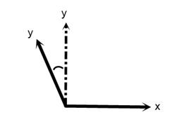
-
VirtualYAxis ORT: X ORV: +30
-
This figure shows the XY plane, with the positive Z coming out of the page. The solid lines represent the machine axes, the dotted line represents the programmed Y axis.
-
In Figure 1, the programmed Y drives the virtual Y axis (dotted line), which results in the machines X and Y axes moving. Here the machines Y axis is 30 degrees from the orthogonal Y axis (positive is counter clockwise looking down the Z axis towards negative Z). If you were currently at X0 Y0 Z0, and you gave the command X0 Y10 Z0, both X and Y would move to achieve this virtual location. In this case, you would call this macro with a value of 30, and a Text value of “X”.
-
VirtualYAxis ORT: Z ORV: -30
-
This figure shows the YZ plane, with the positive X coming out of the page. The solid lines represent the machine axes, the dotted line represents the programmed Y axis.
-
In Figure 2, the programmed Y drives the virtual Y axis, which results in the machines Y and Z axes moving. Here the machines Y axis is negative 30 degrees from the orthogonal Y axis (negative is clockwise looking down the X axis toward negative X). If you were currently at X0 Y0 Z0, and you gave the command X0 Y10 Z0, both Y and Z would move to achieve this virtual location. In this case, you would call this macro with a value of -30, and a Text value of “Z”.
VirtualZAxisABDynamic
-
Function — MISCELLANEOUS
-
Status — ACTIVE
-
Input —
- Text: Not Used
- Value: 0 = Off (Default), 1 = On
-
Comment — Added V7.0.1
-
Input —
- Text: Not Used
- Value: 0 = Off (Default), 1 = On
Turns On, and Off, the dynamic calling of the VirtualZAxisABRotary macro. If the ABC angles are being calculated from IJK points, then the VirtualZAxisABRotary macro needs to be called after the A and B angles have been set. This is done by calling this macro. A value of 0 turns this feature off, a value of 1 turns this feature on.
VirtualZAxisABRotary
-
Function — MISCELLANEOUS
-
Status — ACTIVE
-
Input —
- Text: Not Used
- Value: Not Used
-
Comment — Added V7.0.1
-
Input —
- Text: Not Used
- Value: Not Used
This macro is used to establish a virtual Z axis using rotation planes. The input angle is defined by the local AB axis value. The AAxisMotion and BAxisMotion) macros are used to specify incremental/absolute, and must be called prior to calling this macro. These angles define the angles at which the real Z axis is offset from the virtual orthogonal Z axis.
VirtualZAxisADynamic
-
Function — MISCELLANEOUS
-
Status — ACTIVE
-
Input —
- Text: Not Used
- Value: 0 = Off (Default), 1 = On
-
Comment — Added V6.2.2
-
Input —
- Text: Not Used
- Value: 0 = Off (Default), 1 = On
This macro turns on, and off, the dynamic calling of the VirtualZAxisARotary macro. If the ABC angles are being calculated from IJK points, then the VirtualZAxisARotary macro needs to be called after the A angle has been set. This is done by calling this macro. A value of 0 turns this feature off, a value of 1 turns this feature on.
VirtualZAxisARotary
-
Function — MISCELLANEOUS
-
Status — ACTIVE
-
Input —
- Text: Not Used
- Value: Not Used
-
Comment — Added V6.2.2
-
Input —
- Text: Not Used
- Value: Not Used
Use to establish a virtual Z axis using rotation planes. The input angle is defined by the local A-axis value. The AAxisMotion macro is used to specify incremental/absolute, and must be called prior to calling this macro. This angle defines the angle at which the real Z-axis is offset from the virtual orthogonal Z axis.
VirtualZAxisBRotary
-
Function — Miscellaneous
-
Status — Active
-
Input —
- Text: Not Used
- Value: Not Used
Establish a virtual Z axis using rotation planes. The input angle is defined by the local B axis value. The BAxisMotion macro is used to specify incremental/absolute, and must be called prior to calling this macro. This angle defines the angle at which the real Z axis is offset from the virtual othogonal Z axis.
VirtualZAxisDynamic
-
Function — Miscellaneous
-
Status — Active
-
Input —
- Text: Not Used
- Value: 0 = Off (Default), 1 = On
Turns On, and Off the dynamic calling of the VirtualZAxisBRotary macro. If the ABC angles are being calculated from IJK points, then the VirtualZAxisBRotary macro needs to be called after the B angle has been set. This is done by calling this macro. A value of 0 turns this feature off, a value of 1 turns this feature on.
VoltageOff
-
Function — WIRE EDM
-
Status — ACTIVE
-
Input —
- Text: Not Used
- Value: Not Used
Controls when a SPINDLE/OFF statement is output during wire EDM machining.
VoltageOn
-
Function — WIRE EDM
-
Status — ACTIVE
-
Input —
- Text: Not Used
- Value: Not Used
Controls when a SPINDLE/ON statement is output during wire EDM machining.
W2AxisIncreMotion
-
Function — MOTION
-
Status — ACTIVE
-
Input —
- Text: Not Used
- Value: Incremental amount to move the component.
Specifies the incremental amount to move the W2 axis component on the current subsystem. This will be processed at the end of the block, or when ProcessMotion is called.
Travel Limit warnings for this component will be turned off for this motion.
With robot, if SetRobotLogicVersion is set with value lower than 3, it will also implicitly set motion to Forward Kinematics (Direct Drive of axis) for compatibility with older configurations:
-
CartesianModeOnOff Value = 0
-
SetRobotMotionType Value = 0
W2AxisMachineMotion
-
Function — MOTION
-
Status — ACTIVE
-
Input —
- Text: Not Used
- Value: Position to move component in the machine coordinate system
Specifies the absolute position, within the machine coordinate system, to move the W2 axis component on the current subsystem. This will be processed at the end of the block, or when ProcessMotion is called.
Travel Limit warnings for this component will be turned off for this motion.
With robot, if SetRobotLogicVersion is set with value lower than 3, it will also implicitly set motion to Forward Kinematics (Direct Drive of axis) for compatibility with older configurations:
-
CartesianModeOnOff Value = 0
-
SetRobotMotionType Value = 0
W2AxisMachineRefMotion
-
Function — MOTION
-
Status — ACTIVE
-
Input —
- Text: Not used
- Value: Position to move component relative to the reference location.
Specifies the position, relative to the Machine Reference Location, to move the W2 axis component on the current subsystem. This will be processed at the end of the block, or when ProcessMotion is called.
More specifically, this macro adds the input value and the corresponding value from the Machine Reference Location table, and then calls W2AxisMachineMotion.
See also — W2AxisMachineMotion (ref. Machine Reference Location table in the Tables for Processing G-Codes section, in the CGTech Help Library).
W2AxisMotion
-
Function — MOTION
-
Status — ACTIVE
-
Input —
- Text: Not used
- Value: Position to move component within the local coordinate system.
Sets the local axis position for the W2 axis component on the current subsystem. This will be processed at the end of the block, or when ProcessMotion is called.
The above is the simple description of this macro based on how this macro is most commonly used. There is, however, a series of special logic that could apply under special circumstances.
- If the IncrementalValue function was used to set the value, the input value will be added to the current W2 Axis value.
- If we are incremental mode (ModeIncremental), the value will be added to the existing value.
-
With robot, if SetRobotLogicVersion is set with value lower than 3, it will also implicitly set motion to Forward Kinematics (Direct Drive of axis) for compatibility with older configurations:
-
CartesianModeOnOff Value = 0
-
SetRobotMotionType Value = 0
-
W2AxisMotionLimit
-
Function — MOTION
-
Status — ACTIVE
-
Input —
- Text: Optional MIN, MAX, or MINMAX
- Value: Position to move component within the local coordinate system.
-
Comment — Added V9.3
-
Input —
- Text: Optional MIN, MAX, or MINMAX
- Value: Position to move component within the local coordinate system.
Sets the local axis position for the W2 axis component on the current subsystem. This will be processed at the end of the block, or when ProcessMotion is called. This macro is nearly identical to W2AxisMotion, except it also has a limit feature. If the value would cause the machine to exceed its travel limit, the value is adjusted to the travel limit. This adjustment is done as the value is read in, and therefore all future time calculations, travel limit checks, and local axis positions are based on this adjusted value.
Note — The limit calculations support all of the offsets, but do not support matrices (Working Plane, Rotation Plane, RPCP, Virtual Axis, and Siemens Frames). A corresponding limit macro exists for each of the linear motion axes.
The above is the simple description of this macro based on how this macro is most commonly used. There is, however, a series of special logic that could apply under special circumstances:
- If we are incremental mode (ModeIncremental), the value will be added to the existing value.
-
With robot, if SetRobotLogicVersion is set with value lower than 3, it will also implicitly set motion to Forward Kinematics (Direct Drive of axis) for compatibility with older configurations:
-
CartesianModeOnOff Value = 0
-
SetRobotMotionType Value = 0
-
WarningMacro
-
Function — MISCELLANEOUS
-
Status — ACTIVE
-
Input —
- Text: Text of the warning message
- Value: Not Used
-
Comment — Added V6.0.1
-
Input —
- Text: Text of the warning message
- Value: Not Used
This macro enables you to configure warning messages and conditions.
WaterJetOnOff
-
Function — MISCELLANEOUS
-
Status — ACTIVE
-
Input —
- Text: Not Used
- Value: - 0 = Off
-
Comment — Added V6.2
-
Input —
- Text: Not Used
- Value:
- 0 = Off
- Any other value = On
This macro is macro is used for the simulation of Water Jet cutting. Call this macro with Override Value = 1 to turn the water jet "On" so that the water jet is visible in Vericut, cuts material, and undergoes the appropriate collision checks. Call with Override Value = 0 to turn the water jet "Off" so that it becomes invisible in the Vericut display, does not cut material, and is not used in the collision checking.
WAxisIncreMotion
-
Function — MOTION
-
Status — ACTIVE
-
Input —
- Text: Not Used
- Value: Incremental amount to move the component
Specifies the incremental amount to move the W axis component on the current subsystem. This will be processed at the end of the block, or when ProcessMotion is called. Travel Limit warnings for this component will be turned off for this motion.
With robot, if SetRobotLogicVersion is set with value lower than 3, it will also implicitly set motion to Forward Kinematics (Direct Drive of axis) for compatibility with older configurations:
-
CartesianModeOnOff Value = 0
-
SetRobotMotionType Value = 0
WAxisMachineMotion
-
Function — MOTION
-
Status — ACTIVE
-
Input —
- Text: Not used
- Value: Position to move component in the machine coordinate system
Specifies the absolute position, within the machine coordinate system, to move the W axis component on the current subsystem. This will be processed at the end of the block, or when ProcessMotion is called.
Travel Limit warnings for this component will be turned off for this motion.
With robot, if SetRobotLogicVersion is set with value lower than 3, it will also implicitly set motion to Forward Kinematics (Direct Drive of axis) for compatibility with older configurations:
-
CartesianModeOnOff Value = 0
-
SetRobotMotionType Value = 0
WAxisMachineRefMotion
-
Function — MOTION
-
Status — ACTIVE
-
Input —
- Text: Not used
- Value: Position to move component relative to the reference location.
Specifies the position, relative to the Machine Reference Location, to move the W axis component on the current subsystem. This will be processed at the end of the block, or when ProcessMotion is called.
More specifically, this macro adds the input value and the corresponding value from the Machine Reference Location table, and then calls WAxisMachineMotion.
See also — WAxisMachineMotion (ref. Machine Reference Location table in the Tables for Processing G-Codes section, in the CGTech Help Library).
WAxisMotion
-
Function — MOTION
-
Status — ACTIVE
-
Input —
- Text: Not Used
- Value: Position to move component within the local coordinate system.
Sets the local axis position for the W axis component on the current subsystem. This will be processed at the end of the block, or when ProcessMotion is called.
The above is the simple description of this macro based on how this macro is most commonly used. There is, however, a series of special logic that could apply under special circumstances.
- If the IncrementalValue function was used to set the value, the input value will be added to the current W Axis value.
- If we are in a Drill Cycle mode, and the CycleXyzDepth is set to TRUE (default), and we are in the XY motion plane, and we are executing the drill cycle on motion, the input value will be interpreted as a drill cycle depth value rather than a W axis position value.
-
If we are incremental mode (ModeIncremental), the value will be added to the existing value.
-
With robot, if SetRobotLogicVersion is set with value lower than 3, it will also implicitly set motion to Forward Kinematics (Direct Drive of axis) for compatibility with older configurations:
-
CartesianModeOnOff Value = 0
-
SetRobotMotionType Value = 0
-
WAxisMotionLimit
-
Function — MOTION
-
Status — ACTIVE
-
Input —
- Text: Optional MIN, MAX, or MINMAX
- Value: Position to move component within the local coordinate system.
-
Comment — Added V7.2
-
Input —
- Text: Optional MIN, MAX, or MINMAX
- Value: Position to move component within the local coordinate system.
Sets the local axis position for the W axis component on the current subsystem. This will be processed at the end of the block, or when ProcessMotion is called.
This macro is nearly identical to WAxisMotion, except it also has a limit feature. If the value would cause the machine to exceed its travel limit, the value is adjusted to the travel limit. This adjustment is done as the value is read in, and therefore all future time calculations, travel limit checks, and local axis positions are based on this adjusted value.
Note — The limit calculations support all of the offsets, but do not support matrices (Working Plane, Rotation Plane, RPCP, Virtual Axis, and Siemens Frames). A corresponding limit macro exists for each of the linear motion axes The above is the simple description of this macro based on how this macro is most commonly used. There is, however, a series of special logic that could apply under special circumstances:
- If we are in a Drill Cycle mode, and the CycleXyzDepth is set to TRUE (default), and we are in the XY motion plane, and we are executing the drill cycle on motion, the input value will be interpreted as a drill cycle depth value rather than a W axis position value.
- If 2D rotations or Mirroring is being applied (not using rotation planes), the value will be adjusted accordingly
- If we are incremental mode (ModeIncremental), the value will be added to the existing value.
-
With robot, if SetRobotLogicVersion is set with value lower than 3, it will also implicitly set motion to Forward Kinematics (Direct Drive of axis) for compatibility with older configurations:
-
CartesianModeOnOff Value = 0
-
SetRobotMotionType Value = 0
-
WAxisMotionNoCycle
-
Function — MOTION
-
Status — ACTIVE
-
Input —
- Text: Not Used
- Value: Position to move component within the local coordinate system
This macro is the same as macro WAxisMotion, except that the value is never interpreted as a cycle depth value.
WAxisZeroTracking
-
Function — MOTION
-
Status — ACTIVE
-
Input —
- Text: Not Used
- Value: ZW Tracking value
This macro is used to set the W value used to process the machine's W component on a Zero Tracking machine. In general for Zero Tracking, the local Z value + the local W value = the programmed value. Another way to state this is that the programmed value drives the tool tip to the specified distance in Z from the Program Zero point. If both Z and W are specified on a block, the Secondary axis is driven to its specified Machine Axis location, and Primary axis is driven to the location as specified above.
See Also — WPrimaryTrackingAxis, ZPrimaryTrackingAxis, and ZAxisZeroTracking
WhileLoop
-
Function — BRANCHING
-
Status — ACTIVE
-
Input —
- Text: Not Used
- Value: Value of the expression
Sets the while condition to the input value.
This command is used with DoLoop to process a "while/do" loop of the form:
- While (expression) DO1
- END1
The following Word Formats should be defined:
-
WHILE, DO and END should be defined as a word of Type = "Macro", Sub Type = "Numeric".
-
() represent words of type left and right precedence.
Entries should be defined for WHILE, DO, and END in the Word/Address table as illustrated below:
WireEDM_UV_Plane
-
Function — WIRE EDM
-
Status — ACTIVE
-
Input —
- Text: Not Used
-
Comment — Added V9.7
-
Input —
- Text: Not Used
- Value: Z level of the UV Plane
For Wire EDM, this macro specifies the Z level of the UV Plane. The Z level is specified in machine coordinates, which typically matches the local coordinates for Wire EDM machines.
This macro is only used when WireEDMLogic is set to 2.
WireEDM_UVMotionState
-
Function — WIRE EDM
-
Status — ACTIVE
-
Input —
- Text: Not Used
-
Comment — Added V9.7
-
Input —
- Text: Not Used
- Value: UV motion type: 0=Rapid, 1=Linear, 2=CW, 3=CCW, 4=From
For Wire EDM controls that support dual motion types (such as Agie), this macro specifies the motion type for the UV motion independently of the XY motion type.
Valid values are 0 through 4. A value of 0 (Rapid) is only valid when the current motion type is also Rapid. Conversely, if the current motion type is Rapid, only a value of 0 is accepted.
This macro only needs to be called for controls that support dual (UV/XY) motion types.
WireEDM_XY_Plane
-
Function — WIRE EDM
-
Status — ACTIVE
-
Input —
- Text: Not Used
-
Comment — Added V9.7
-
Input —
- Text: Not Used
- Value: Z level of the XY Plane
For Wire EDM, this macro specifies the Z level of the XY Plane. The Z level is specified in machine coordinates, which typically matches the local coordinates for Wire EDM machines.
This macro is only used when WireEDMLogic is set to 2.
WireEDM_XYSetsUVMotionState
-
Function — WIRE EDM
-
Status — ACTIVE
-
Input —
- Text: Not Used
-
Comment — Added V9.7
-
Input —
- Text: Not Used
- Value: 0 = FALSE (default), 1 = TRUE
For Wire EDM controls that support dual motion types, this macro specifies whether the U and V axes should be automatically set to the X and Y axis values on blocks where WireEDM_UVMotionState has not been called.
This macro is typically called once at the start of processing. When set to TRUE, any block that does not explicitly set the UV motion state via WireEDM_UVMotionState will have its U and V axis values overridden with the corresponding X and Y axis values.
Note: By setting the UV values to be the same as XY, it means that the wire is vertical.
Setting this macro to TRUE is only valid when UV Incremental XY is disabled. An error will be reported if TRUE is specified while UV Incremental XY is enabled.
WireEDMCutWidth
-
Function — WIRE EDM
-
Status — ACTIVE
-
Input —
- Text: Not Used
- Value: Width of cut
This macro specifies the width of the cut for Wire EDM. The cut width defaults to the Wire Diameter.
By changing the voltage on the wire, you can change the amount of "burn" which modifies the width of the cut. Visually, the width of the wire is based on the Wire Diameter, and the cut width is based on this macro.
If the wire is already "threaded", this cut width will apply immediately. Otherwise, it will be applied the next time WireEDMThreadWire is called.
WireEDMLogic
-
Function — WIRE EDM
-
Status — ACTIVE
-
Input —
- Text: Not Used
- Value: 1 = Original 2 = New in V9.7
-
Comment — Added V9.7
-
Input —
- Text: Not Used
- Value:
- 1 = Original logic (default)
- 2 = Wire EDM logic 2 (new in V9.7)
This macro specifies which Wire EDM logic to use. We now have two different ways in which we specify Wire EDM parameters. The two options require different inputs, which means that changing the Wire EDM logic requires other configuration changes.
Option 1: EDM macros are used to specify distance between different levels
Option 2: WireEDM macros are used to specify the Z level of the XY and UV planes. Option 2 will be used for all future enhancements
WireEDMModeOnOff
-
Function — WIRE EDM
-
Status — ACTIVE
-
Input —
- Text: Not used
- Value: 0 = OFF, 1 = On
-
Comment — Added in V9.6.x
- Input —
- Text: Not used
- Value: 0 = OFF, 1 = On
Description —
This macro allows you to turn on and off WireEDMMode. If processing Wire EDM, the WireEDMMode must be set to On. If you are not processing Wire EDM, the WireEDMMode must be set to Off.
If the "Default Machining Type" (in the Project/Settings/Properties window) is set to Wire EDM, the default WireEDMMode will be set to ON. Otherwise, the dafault WireEDMMode will be set to OFF.
Note — If the machine is ever to be in WireEDMMode, than the WireEDMMODE must be set to On at reset. This means either the "Default MachiningType" is set to Wire EDM, or that this macro is called during the Reset event.
WireEDMThreadWire
-
Function — WIRE EDM
-
Status — ACTIVE
-
Input —
- Text: Not Used
- Value: Not Used
Thread the wire. This will cause the Wire to be displayed between the upper and lower guides, and a "PPRINT/Vericut-TC" statement to be printed. For material removal purposes, the height for the cutter will be set to the maximum length of the wire based off of the vertical distance between the guides, and the maximum angle.
This macro is similar to ThreadWire except this macro uses the width specified by the WireEDMCutWidth macro. Note: By changing the voltage on the wire, you can change the amount of "burn" which modifies the width of the cut. Visually, the width of the wire is based on the Wire Diameter, and the cut width is based on the WireEDMCutWidth.
This macro should be called again if the z positioning of the Guides change while the wire is threaded.
WorkCoord
-
Function — WORK OFFSETS
-
Status — ACTIVE
-
Input —
- Text: Optional argument: ERROR
- Value: Index into the Work Offset table
Updates the work coordinate system based off of the values in the Work Offsets table (ref. Work Offsets table in the Tables for Processing G-Codes section, in the Vericut Help Library). The input value is used as an index into this table. Any non-negative number is valid. Outputs an error message if the corresponding table entry does not exist, and "ERROR" is specified as the Text value.
WorkCoordA2Value
-
Function — WORK OFFSETS
-
Status — ACTIVE
-
Input —
- Text: Optional Argument: MIRROR
- Value: Axis value
This macro sets the A2 axis parameter value. This parameter value is then used in various work and Shift offset macros. A corresponding macro exists for each motion axis:
- When this macro is called with an Override Text value of "MIRROR", and the A2 Axis is set to mirror, the input value will be mirrored.
WorkCoordA3Value
-
Function — WORK OFFSETS
-
Status — ACTIVE
-
Input —
- Text: Optional Argument: MIRROR
- Value: Axis value
This macro sets the A3 axis parameter value. This parameter value is then used in various work and Shift offset macros. A corresponding macro exists for each motion axis:
- When this macro is called with an Override Text value of "MIRROR", and the A3 Axis is set to mirror, the input value will be mirrored.
WorkCoordAValue
-
Function — WORK OFFSETS
-
Status — ACTIVE
-
Input —
- Text: Optional Argument: MIRROR
- Value: Axis value
This macro sets the A axis parameter value. This parameter value is then used in various work and Shift offset macros. A corresponding macro exists for each motion axis:
- When this macro is called with an Override Text value of "MIRROR", and the A Axis is set to mirror, the input value will be mirrored.
WorkCoordB2Value
-
Function — WORK OFFSETS
-
Status — ACTIVE
-
Input —
- Text: Optional Argument: MIRROR
- Value: Axis value
This macro sets the B2 axis parameter value. This parameter value is then used in various work and Shift offset macros. A corresponding macro exists for each motion axis:
- When this macro is called with an Override Text value of "MIRROR", and the B2 Axis is set to mirror, the input value will be mirrored.
WorkCoordB3Value
-
Function — WORK OFFSETS
-
Status — ACTIVE
-
Input —
- Text: Optional Argument: MIRROR
- Value: Axis value
This macro sets the B3 axis parameter value. This parameter value is then used in various work and Shift offset macros. A corresponding macro exists for each motion axis:
- When this macro is called with an Override Text value of "MIRROR", and the B3 Axis is set to mirror, the input value will be mirrored.
WorkCoordBValue
-
Function — WORK OFFSETS
-
Status — ACTIVE
-
Input —
- Text: Optional Argument: MIRROR
- Value: Axis value
This macro sets the B axis parameter value. This parameter value is then used in various work and Shift offset macros. A corresponding macro exists for each motion axis:
- When this macro is called with an Override Text value of "MIRROR", and the B Axis is set to mirror, the input value will be mirrored.
WorkCoordC2Value
-
Function — WORK OFFSETS
-
Status — ACTIVE
-
Input —
- Text: Optional Argument: MIRROR
- Value: Axis value
This macro sets the C2 axis parameter value. This parameter value is then used in various work and Shift offset macros. A corresponding macro exists for each motion axis:
- When this macro is called with an Override Text value of "MIRROR", and the C2 Axis is set to mirror, the input value will be mirrored.
WorkCoordC3Value
-
Function — WORK OFFSETS
-
Status — ACTIVE
-
Input —
- Text: Optional Argument: MIRROR
- Value: Axis value
This macro sets the C3 axis parameter value. This parameter value is then used in various work and Shift offset macros. A corresponding macro exists for each motion axis:
- When this macro is called with an Override Text value of "MIRROR", and the C3 Axis is set to mirror, the input value will be mirrored.
WorkCoordCValue
-
Function — WORK OFFSETS
-
Status — ACTIVE
-
Input —
- Text: Optional Argument: MIRROR
- Value: Axis value
This macro sets the C axis parameter value. This parameter value is then used in various work and Shift offset macros. A corresponding macro exists for each motion axis:
- When this macro is called with an Override Text value of "MIRROR", and the C Axis is set to mirror, the input value will be mirrored.
WorkCoordIndex
-
Function — WORK OFFSETS
-
Status — ACTIVE
-
Input —
- Text: Not Used
- Value: Index (or Register value) into the Work Offset Table.
This macro is used to set the Register value that is used with the Work Offset tables.
The default is 1. This value is non-modal. This value will be used with the following macros:
WorkCoordU2Value
-
Function — WORK OFFSETS
-
Status — ACTIVE
-
Input —
- Text: Not Used
- Value: U2 axis position value (units-sensitive)
Sets the U2 axis component of a pending offset. The stored value is not applied immediately — it is picked up by whichever work or shift offset macro is called next (such as SetWorkCoord, AbsoluteShift, etc.).
This macro is one of a family of 18 axis-value macros, one for each motion axis. Any axis not explicitly set before the offset macro is called is either treated as zero or left unchanged (depending on the offset macro).
WorkCoordUValue
-
Function — WORK OFFSETS
-
Status — ACTIVE
-
Input —
- Text: Not Used
- Value: Axis Value
This macro sets the U axis parameter value. This parameter value is then used in various work and Shift offset macros. A corresponding macro exists for each motion axis:
- When this macro is called with an Override Text value of "MIRROR", and the U Axis is set to mirror, the input value will be mirrored.
WorkCoordV2Value
-
Function — WORK OFFSETS
-
Status — ACTIVE
-
Input —
- Text: Not Used
- Value: V2 axis position value (units-sensitive)
Sets the V2 axis component of a pending offset. The stored value is not applied immediately — it is picked up by whichever work or shift offset macro is called next (such as SetWorkCoord, AbsoluteShift, etc.).
This macro is one of a family of 18 axis-value macros, one for each motion axis. Any axis not explicitly set before the offset macro is called is either treated as zero or left unchanged (depending on the offset macro).
WorkCoordVValue
-
Function — WORK OFFSETS
-
Status — ACTIVE
-
Input —
- Text: Not Used
- Value: Axis Value
This macro sets the V axis parameter value. This parameter value is then used in various work and Shift offset macros. A corresponding macro exists for each motion axis:
- When this macro is called with an Override Text value of "MIRROR", and the V Axis is set to mirror, the input value will be mirrored.
WorkCoordW2Value
-
Function — WORK OFFSETS
-
Status — ACTIVE
-
Input —
- Text: Not Used
- Value: W2 axis offset value (units-sensitive)
Sets the W2 axis component of a pending offset. The stored value is not applied immediately — it is picked up by whichever work or shift offset macro is called next (such as SetWorkCoord, AbsoluteShift, etc.).
This macro is one of a family of 18 axis-value macros, one for each motion axis. Any axis not explicitly set before the offset macro is called is either treated as zero or left unchanged (depending on the offset macro).
WorkCoordWithMotion
-
Function — WORK OFFSETS
-
Status — ACTIVE
-
Input —
- Text: Not Used
- Value: - 0 = Apply offset and cause motion on all axes immediately.
-
0 = Apply offset and cause motion on all axes immediately. - 1 = Apply offset (Default). - 2 = Apply offset and cause motion on all axes with next programmed motion.
This macro should be passed a value of 0, 1, or 2. A value of zero means that the work offset should be applied and cause motion on all axes immediately. A value of one means that the offset will be applied (no impact on motion). A value of two means that the offset will be applied and cause motion on all axes with next programmed motion. The default value is 1. This macro affects all macros which set or cancel the base, primary, or secondary work offsets.
Note — In the case of Fadal, a call to this macro could be made during start of processing.
WorkCoordWValue
-
Function — WORK OFFSETS
-
Status — ACTIVE
-
Input —
- Text: Not Used
- Value: Axis value
This macro sets the W axis parameter value. This parameter value is then used in various work and Shift offset macros. A corresponding macro exists for each motion axis:
- When this macro is called with an Override Text value of "MIRROR", and the W Axis is set to mirror, the input value will be mirrored.
WorkCoordXValue
-
Function — WORK OFFSETS
-
Status — ACTIVE
-
Input —
- Text: Optional argument: MIRROR
- Value: Axis value
This macro sets the X axis parameter value. This parameter value is then used in various work and Shift offset macros. A corresponding macro exists for each motion axis:
- When this macro is called with an Override Text value of "MIRROR", and the X Axis is set to mirror, the input value will be mirrored.
WorkCoordYValue
-
Function — WORK OFFSETS
-
Status — ACTIVE
-
Input —
- Text: Optional argument: MIRROR
- Value: Axis value
This macro sets the Y axis parameter value. This parameter value is then used in various work and Shift offset macros. A corresponding macro exists for each motion axis:
- When this macro is called with an Override Text value of "MIRROR", and the Y Axis is set to mirror, the input value will be mirrored.
WorkCoordZValue
-
Function — WORK OFFSETS
-
Status — ACTIVE
-
Input —
- Text: Optional argument: MIRROR
- Value: Axis value
This macro sets the Z axis parameter value. This parameter value is then used in various work and Shift offset macros. A corresponding macro exists for each motion axis:
- When this macro is called with an Override Text value of "MIRROR", and the Z Axis is set to mirror, the input value will be mirrored.
WorkingPlane
-
Function — ROTATION PLANE
-
Status — ACTIVE
-
Input —
- Text: Name of the variables to store the resulting A,B,C values
- Value: - Specifies the input type
-
Specifies the input type - 1 = Rotation Plane angles - 2 = X-Axis Z-Axis vectors
This macro is identical to the WorkingPlane2Abc macro except that it uses Rotation Plane FOUR for input, and creates Rotation Plane SIX matrix.
WorkingPlane2Abc
-
Function — ROTATION PLANE
-
Status — ACTIVE
-
Input —
- Text: Name of the variables to store the resulting A,B,C values
- Value: - Specifies the input type
-
Specifies the input type - 0 = Rotation Plane angles - 1 = X-Axis Z-Axis vectors
This macro converts the "working plane" into real A, B, C angle that applies to the current machine, and establishes a rotation plane matrix if necessary. The resulting angles are then stored in the specified variables. The text value passed to this macro contains the names of the variables, typically for Heidenhain, this will be set to "120 121 122". This macro makes use of the WorkingPlane2AbcType as defined below. The input value defines how the "working plane" was defined.
This macro uses Rotation Plane FOUR.
Valid Override Values (input types):
- Override Value = 0Rotation Plane Angles and offsets.
These values are set with the following macros:
-
Override Value = 1X and Z Vectors.
These vectors are set with the following macros:
-
Override Value = 2
-
The WorkingPlane2Abc macro with value 2 can be programmed to get the same results for the working plane as using a PAROT command. This option was designed for Heidenhain working plane support without using a CYCLE800 sub. In this case the $P_WPFRAME is replaced by the Rotation Plane) matrix which should be set before calling the WorkingPlane2Abc macro.
-
Override Value = 3X and Y Vectors.
These vectors are set with the following macros:
WorkingPlane2AbcSolution
-
Function — ROTATION PLANE
-
Status — ACTIVE
-
Input —
- Text: Optional argument: FORCE
- Value: - 1 = Closest distance
-
Comment — Added V6.1
-
Input —
- Text: Optional argument: FORCE
- Value:
- 1 = Closest distance
- 2 = Negative solution for the first rotary (first rotary from the tool)
- 3 = Positive solution for the first rotary
- 4 = Use the small value solution for the specified rotary axix
- 5 = Use the large value solution for the specified rotary axis
Anytime you convert a tool axis vector (IJK) to the corresponding 2 angles (A-C, B-C, ...), there are 2 possible solutions. This macro selects the algorithm which will be used to determine the best solution. This setting is non-modal, and must be called prior to calling macro WorkingPlane2Abc. The default setting is closest distance. When using an Override Value of 2, or 3, the solution requested will be used unless it violates travel limits. If this macro is passed "FORCE" as a text string, it will pick the specified solution regardless of travel limits.
The "FORCE" option with an Override Value of 2, or 3, (Negative or Positive solution) is not well defined for Linear tables. Using an Override Value of 4 will cause Vericut to use the small value solution for the specified rotary axis. Using an Override Value of 5 will cause Vericut to use the large value solution for the specified rotary axis. Override Values 4, and 5, are specific to Sinumerik 840D controls.
WorkingPlane2AbcType
-
Function — ROTATION PLANE
-
Status — ACTIVE
-
Input —
- Text: Not Used
- Value: - 1 = Generic A-C. A Nutator may exist on the table.
-
1 = Generic A-C. A Nutator may exist on the table. - 2 = Generic B-C. A Nutator may exist on either head or table - 3 = Special A-C table on table machine with a horizontal head. A nutator on the table is NOT supported. - 4 = Generic B-A. - 5 = Special double angle BC nutator support for DMG DMU 50 eVo Linear machines. This value supports any angle on the nutator. - 99 = Universal (Default)
Typically called during the "Start of Processing" event, this macro controls the type of conversion required to convert a rotated coordinate system into ABC rotations. Conversion type is specified via Override Value.
There are two classes of conversion routines, "Generic" and "Specific". Specific conversion types are meant for a very specific machine/control configuration. Generic conversion types are for any machine/control that follows simple rules.
Generic conversion types:
-
Assume that if the rotaries are set to "Absolute", then the direction will be set to "Shortest Distance".
-
When converting to ABC, typically there are 2 solutions. The Generic routines will choose the solution which requires the smallest total rotary travel.
-
Assume that the control will be configured to handle any RTCP/RPCP issues.
-
Assume that the only rotation applied to components will be on nutator components.
-
Are based on the order that the rotaries appear starting at the Tool, and ending with the Stock. This means that an A on C head machine can use the same Generic conversion type as an A head/C table machine, or a C on A table machine. These 3 machine configurations would all be described as "A-C".
-
Travel limits will be obeyed.
-
If the tool angle is (0,0,1), the C angle will be set to match the input C angle.
Valid Override Values (conversion types):
-
1 = Generic A-C. A Nutator may exist on the table.
-
2 = Generic B-C. A Nutator may exist on either head or table
-
3 = Special A-C table on table machine with a horizontal head. A nutator on the table is NOT supported. It is assumed that the NC program has been posted for a horizontal head machine (Tool along the machines Y axis).
-
4 = Generic B-A.
-
5 = Special double angle BC nutator support for DMG DMU 50 eVo Linear machines. This value upports any angle on the nutator.
-
99 = Universal (Default)
-
The new universal logic is based on a machine configuration where 2 rotary components represent 2 degrees of freedom. When the rotation axes of the rotary components are orthogonal (axes are independent) the conversion is satisfied for any IJK values.
-
If the rotation axes are not orthogonal, then only a subset of all IJK values can be satisfied. Although the angle may vary, it must remain constant after the machine is build in order for this logic to work. In other words, if a dormant rotary component is present between the 2 active rotary components, it must remain unchanged during processing. This restriction can be changed in future if needed.
-
The universal method supports both linear, and absolute, rotary axis motion (ref. Control Settings window: Rotary tab in the Configuration menu section of Vericut Help, in the Vericut Help Library), and reversal of the rotary component's motion direction (ref. Reverse Direction on the Configure Component window, Component Type: All Motion Axes, in the Project Tree section of Vericut Help, in the Vericut Help Library).
-
It adheres to "travel limits" unless Ignore is toggled "On" for a component on the Travel Limits tab for either the G-Code Settings window, or the Machine Settings window (ref. Collision and Travel Limits window: Travel Limits tab in the Project Tree section, or Machine Settings window: Travel Limits tab, in the Configuration menu section, of Vericut Help, in the Vericut Help Library).
WorkingPlane2AbcVertAxisRule
-
Function — ROTATION PLANE
-
Status — ACTIVE
-
Input —
- Text: Not Used
- Value: - 0 = no special rules (use the previous position)
-
Comment — Added V6.2
-
Input —
- Text: Not Used
- Value:
- 0 = no special rules (use the previous position)
- 1 = apply the special logic specific to Sinumerik 840D controls
This macro is used to specify when to use an optional set of rules, specific to Sinumerik 840D controls, is used for calculating the second rotary axis position. The Sinumerik 840D control requires that the rotation of the second rotary axis be in a specific direction.
For situations where the tool axis vector is parallel to the second rotary axis, the position of the second rotary axis is irrelevant, so the previous rotary position can be applied (no new rotation of the axis). Use an Override Value of 0.
For all other cases, use an Override Value of 1 to invoke the special logic specific to Sinumerik 840D controls where the rotation of the second rotary axis is restricted to a specific direction.
WorkingPlane2AbcVertRiderOffset
-
Function — ROTATION PLANE
-
Status — Active
-
Input —
- Text: Optional argument: RESET
- Value: Offset value used to override the calculated angle
-
Comment — Added V7.3.3
-
Input —
- Text: Optional argument: RESET
- Value: Offset value used to override the calculated angle
This macro is specific to the Siemens 840D CYCLE800 subroutine (Working Plane programming). Its purpose is to set a specific angle for the Rider rotary axis when it is vertical to the Carrier plane (coaxial with the tool vector) and the X-axis of the Working Plane is not at a zero degree angle relative to the Rider.
In most cases the calculated angle is correct, however on some machines it can be also affected by _DIR parameter of CYCLE800 subroutine. Using this macro, you can override the calculated angle by adding a specified offset value in Override Value field. Usually it is 180 for _DIR=1 and -180 for _DIR=-1. By specifying RESET in the Override Text field, you can reset the previously programmed offset.
See Also — WorkingPlane2AbcVertAxisRule and related macros.
WorkingPlane2AbcVertRiderRule
-
Function — = ROTATION PLANE
-
Status — = ACTIVE
-
Input —
- Text: Not Used
- Value: - 0 = If tool is vertical, don’t rotate it
-
Comment — = Added V7.3
-
Input —
- Text: Not Used
- Value:
- 0 = If tool is vertical, don’t rotate it
- 1 = If tool is vertical, apply the X axis rotation (Default)
This macro is used to support the case where the tool is vertical and the ZAxis and XAxis are both given. Set the Override Value = 0 to support this case (ignore X axis of the Working Plane matrix and keep the old rider value). The default is Override Value = 1. This is necessary to preserve existing 840D controls without changing configuration.
WorkingPlane2AbcVertRiderZero
-
Function — ROTATION PLANE
-
Status — Active
-
Input —
- Text: Optional argument: RESET
- Value: Offset value used to override the calculated angle
-
Comment — Added V7.3.3
-
Input —
- Text: Optional argument: RESET
- Value: Offset value used to override the calculated angle
This macro is specific to the Siemens 840D CYCLE800 subroutine (Working Plane programming). Its purpose is to set a specific angle for the Rider rotary axis when it is vertical to the Carrier plane (coaxial with tool vector) and the X-axis of Working Plane is at a zero degree angle relative to the Rider.
In most cases this angle is 0, however on some machines it can be also affected by _DIR parameter of CYCLE800 subroutine. Using this macro, you can override the calculated angle by specifying the desired angle in Override Value field. Usually it is 0 for _DIR=-1 and 180 for _DIR=1. By specifying RESET in the Override Text field, you can reset a previously programmed zero position.
See Also — WorkingPlane2AbcVertAxisRule and related macros.
WorkingPlaneCancel
-
Function — ROTATION PLANE
-
Status — ACTIVE
-
Input —
- Text: ONE, TWO, THREE, FOUR, FIVE, SIX (default) or SEVEN
- Value: Not Used
-
Comment — Added V7.0.3
-
Input —
- Text: ONE, TWO, THREE, FOUR, FIVE, SIX (default) or SEVEN
- Value: Not Used
This macro is used to cancel the specified Rotation Plane.
Note — The matrix is kept so that it can be later enabled if desired, and this macro also converts the local XYZ into the new coordinate system.
WorkingPlaneDWO
-
Function — ROTATION PLANE
-
Status — ACTIVE
-
Input —
- Text: Name of the variables to store the resulting A,B,C values
- Value: - Specifies the input type
-
Comment — Added V7.2.3
-
Input —
- Text: Name of the variables to store the resulting A,B,C values
- Value:
- Specifies the input type
- 0 = Rotation Plane angles
- 1 = X-Axis Z-Axis vectors
-
This macro is identical to the WorkingPlane macro except that it also updates the work offsets as if the Dynamic Work Offsets (DWO) are turned on, and the part had already been rotated to the new calculated location.
- This macro is created specifically for the Heidenhain control, but may be useful for other controls.
- This macro converts the "working plane" into real A, B, and C angles that apply to the current machine, and establishes a working plane matrix if necessary. The resulting angles are then stored in the specified variables. The text value passed to this macro contains the names of the variables, typically for Heidenhain, this will be set to "120 121 122".
- This macro uses Rotation Plane FOUR for input, and creates Rotation Plane SIX matrix.
- The input value defines how the working plane" was defined.
- This macro makes use of the WorkingPlane2AbcType macro.
Valid Override Values (input types):
- Override Value = 0 Rotation Plane Angles and offsets.
These values are set with the following macros:
-
Override Value = 1 X and Z Vectors.
These vectors are set with the following macros:
WorkingPlaneEnable2
-
Function — ROTATION PLANE
-
Status — ACTIVE
-
Input —
- Text: ONE, TWO, THREE, FOUR (default), FIVE, SIX or SEVEN
- Value: Not Used
-
Comment — Added V7.4
-
Input —
- Text: ONE, TWO, THREE, FOUR (default), FIVE, SIX or SEVEN
- Value: Not Used
This macro is used to enable a previously established working plane matrix. This macro also converts the local XYZ into the new coordinate system. The Text argument specifies which Rotation Plane we are enabling.
WorkingPlaneRelative
-
Function — WORK OFFSETS
-
Status — ACTIVE
-
Input —
- Text: 3 variable names to store A,B,C values, followed by a mode value
- Value: - 0 = reset to the last applied working plane
-
Comment — Added V7.1.6
-
Input —
- Text: 3 variable names to store A,B,C values, followed by a mode value
- Value:
- 0 = reset to the last applied working plane
- 1 = apply the calculated angles
This macro is equivalent to the SiemensPAROT macro and is designed to process the Working Plane definition similar to the Sin840D PAROT command for non-Siemens controls, like Heidenhain.
WorkOffsetRelative
-
Function — WORK OFFSETS
-
Status — ACTIVE
-
Input —
- Text: Not Used
- Value: - 0 = use the old Sin840D PAROT logic
-
Comment — Added V7.1.6
-
Input —
- Text: Not Used
- Value:
- 0 = use the old Sin840D PAROT logic
- 1 = use the new Sin840D PAROT logic
- 2 = this value is no longer used
- 3= used to solve the PAROT command in a CYCLE800 subroutine
This macro is used to activate new logic to process the Sin840D PAROT command. If the Override Value is set to 0, then the old PAROT logic is applied.
When the Override Value is set to 1, the new logic is applied. The new logic is similar to the old logic except that it is enhanced to better handle more cases of machine kinematics that previously not handled correctly.
When the Override Value is set to 3, this macro is used to solve the PAROT command in a CYCLE800 subroutine with the additional conversion of a working plane matrix $P_WPFRAME (calculated in CYCLE800) thru the current/active Work Offset rotation specified in $P_IFRAME (corresponding G54 or G55 etc.).
WorkPieceErrorCompensation
-
Function — ROTATION PLANE
-
Status — ACTIVE
-
Input —
- Text: Not Used
- Value: 0 = Off, anything else = On
-
Comment — Added V9.4
-
Input —
- Text: Not Used
- Value: 0 = Off, anything else = On
This macro turn On/Off the Work Piece Error Compensation. Prior to calling this macro WPCreate should be call. This will fully define the Work Piece Error Compensation (rotations and offsets). The rotary compensation will be saved and applied to all future rotary moves. The offset will be applied immediately as a shift offset. While Work Piece Error Compensation is action, all rotary moves should call the Ijk[ABC]AxisMotion. The rotary motion will be converted to a matrix. This matrix will be adjusted by the Error Compensation, and the resulting matrix will be used as input to WPCreate.
Note — Sometimes a small Error Compensation can cause a large change in the resulting angles.
WPAbsoluteShiftLocal
-
Function — ROTATION PLANE
-
Status — ACTIVE
-
Input —
- Text: Optional: “MODAL”
- Value: Specifies which shift index to use (0, 1, 2)
-
Comment — Added V8.0
-
Input —
- Text: Optional: “MODAL”
- Value: Specifies which shift index to use (0, 1, 2)
This macro implements an absolute shift. This shift is specified with the WorkCord… macros. This input is in local coordinates, and is for the current rotation as defined by the current Working Plane – not necessarily the current rotation of the machine.
Note — Dynamic Work Offsets are turned on for this calculation, and then restored afterwards.
If “MODAL” is set, it will only update the fields that were specified. This is very complicated, lets look at an example:
- A working plane is established where the C table rotates 90 degrees (with no change in the CSYS). The WPAbsoluteShiftLocal macro is called with a Y5 Z10 shift. We will convert this to be a X5 Z10 offset that is rotated 90 degrees. This macro is then called again, this time with a Y7. The current X5 Z10 offset will be converted back to Y5 Z10, and then only the Y will be updated. Then end result is a Y7 Z10 offset which is then converted to a X7 Z10 offset that is rotated 90.
WPAbsoluteShiftLocalTable
-
Function — ROTATION PLANE
-
Status — ACTIVE
-
Input —
- Text: Optional: “MODAL”
- Value: Specifies which shift index to use (0, 1, 2)
-
Comment — Added V8.0
-
Input —
- Text: Optional: “MODAL”
- Value: Specifies which shift index to use (0, 1, 2)
This macro implements an absolute shift. The shift amount is specified in the Shift Offsets table. See also: WorkCoordIndex and WPAbsoluteShiftLocalTable.
This input is in local coordinates, and is for the current rotation as defined by the current Working Plane – not necessarily the current rotation of the machine.
Note —
-
Dynamic Work Offsets are turned on for this calculation, and then restored afterwards. If “MODAL” is set, it will only update the fields that were specified. This is very complicated. See also: AbsoluteShift for an example. SYSWRITE – ID 500/501 This command updates the Shift Offsets table. NR sets the Register value (row number), the SubRegister value is set to 1 and the IDX value specifies the axis to set (1-9 corresponding to X, Y, Z, A, B, C, U, V and W).
-
Existing values are modal. Only the specified value is being updated. SYSWRITE – ID 502 This command updates the Work Offsets table. NR sets the Register value (row number), the SubRegister value is set to 1, and the IDX value specifies the axis to set (1-9 corresponding to X, Y, Z, A, B, C, U, V and W). The Value is interpreted to be in local coordinates.
-
Existing values are modal. Only the specified value is being updated. SYSWRITE – ID 503 This command updates the Work Offsets table. NR sets the Register value (row number), the SubRegister value is set to 1, and the IDX value specifies the axis to set (1-9 corresponding to X, Y, Z, A, B, C, U, V and W). The Value is interpreted to be in local coordinates.
WPAdjustOffsets
-
Function — ROTATION PLANE
-
Status — ACTIVE
-
Input —
- Text: NO_OFFSETS (Optional)
- Value: not used
-
Comment — Added V8.0
-
Input —
- Text: NO_OFFSETS (Optional)
- Value: not used
This macro causes the offsets to be updated based on the last Working Plane solution. This macro will:
-
Move the machine to the last Working Plane solution (internally only – just for calculations)
-
Turn on RTCP and DWO
-
Calculate the offsets (Tool, Work, Shift, Program Zero)
-
Restore the RTCP and DWO settings
-
Restore the machine
-
If “NO_OFFSETS” is specified, then the offsets will be calculated as if there were no offsets on the rotary components. This option should rarely be used.
WPApplyMirroring
-
Function — ROTATION PLANE
-
Status — ACTIVE
-
Input —
- Text: Not used
- Value: 1 = Yes, 0 = No (default)
-
Comment — Added in V8.2
-
Input —
- Text: Not used
- Value: 1 = Yes, 0 = No (default)
This macro determines if Mirroring should be applied to the Working Plane input. If yes, it will use the rotation plane specified with RotationPlaneMirrorIndex to determine which mirroring has been turned on.
Note — This Rotation Plane must contain only Mirroring. The Working Plane logic will eventually call the Ijk2Angles logic. If mirroring is to be applied to the Working Plane input, this macro must be called with a value of 1. The Ijk2AnglesApplyMirroring will be ignored while calculating the working plane.
WPAxisValues
-
Function — ROTATION PLANE
-
Status — ACTIVE
-
Input —
- Text: Register name for corresponding axis (A, B, C, A2, B2, C2, A3, B3, C3)
- Value: Axis values
-
Comment — Added V8.1
-
Input —
- Text: Register name for corresponding axis (A, B, C, A2, B2, C2, A3, B3, C3)
- Value: Axis values
This macro stores the specified axis value, which is then later used by WPCreateAxisValues. This macro only applies to rotaries.
WPCreate
-
Function — ROTATION PLANE
-
Status — ACTIVE
-
Input —
- Text: Variable names to store the calculated axis values for A, B, C, followed by an optional Rotation Plane Identifier
- Value: Not Used
-
Comment — Added V8.0
-
Input —
- Text: Variable names to store the calculated axis values for A, B, C, followed by an optional Rotation Plane Identifier
- Value: Not Used
This macro creates the Working Plane. All settings associated with the working plane should be made prior to this call. The working plane logic will use the Ijk2Angles logic to calculate the angles for 2 rotaries to achieve the specified orientation. If the part was not able to be rotated as specified, the Coordinate System will be rotated as needed. The calculated angles will then store in the corresponding variables.
The Rotation Plane Identifier specifies the Rotation Plane that contains the input parameters. Parameters associated with rotation planes are specific to an individual rotation plane. If this field is not present, it defaults to FOUR.
Note —
- The Rotation Plane created by this macro is controlled by the macro WPMatrix.
- If the rotary that was calculated was A2, B2, or C2, it will not be saved to a variable. See also the Ijk2Angles) macros.
WPCreateAxisValues
-
Function — ROTATION PLANE
-
Status — ACTIVE
-
Input —
- Text: Variable names to store axis values for A, B, C.
- Value: Not Used
-
Comment — Added V8.1
-
Input —
- Text: Variable names to store axis values for A, B, C.
- Value: Not Used
This macro creates the Working Plane based on the orientation of the tool when driven to the positions specified with WPAxisValues. The specified angles will then be stored in the corresponding variables. These angles are stored, and are then used with WPAdjustOffsets.
WPDynamicOnOff
-
Function — ROTATION PLANE
-
Status — ACTIVE
-
Input —
- Text: Not Used
- Value: 0 = Off (default), 1 = On
-
Comment — Added V9.4.x
-
Input —
- Text: Not Used
- Value: 0 = Off (default), 1 = On
This macro specifies if the Working Plane logic should be called whenever processing Ijk[ABC]AxisMotion.
This macro was created for a Fanuc control. This macro should be called with a value of 1 when in G68.2/G53.1/G43.4 mode.
This means that a working plane has been established with G68.2/G53.1, and then you are in G43.4 mode where you now specify IJK values.
WPIncrementalShiftLocal
-
Function — ROTATION PLANE
-
Status — ACTIVE
-
Input —
- Text: Not used
- Value: Specifies which shift index to use (0, 1, 2)
-
Comment — Added V8.0
-
Input —
- Text: Not used
- Value: Specifies which shift index to use (0, 1, 2)
This macro implements an incremental shift. This shift is specified with the WorkCord macros. This input is in local coordinates, and is for the current rotation as defined by the current Working Plane – not necessarily the current rotation of the machine.
Note — Dynamic Work Offsets are turned on for this calculation, and then restored afterwards.
WPInput
-
Function — ROTATION PLANE
-
Status — ACTIVE
-
Input —
- Text: Specifies the Rotation Planes to be used for input (only used when value = 4)
- Value: - 1= Rotation Plane Angles (default)
-
Comment — Added V8.0
-
Input —
- Text: Specifies the Rotation Planes to be used for input (only used when value = 4)
- Value:
- 1= Rotation Plane Angles (default)
- 2 = X and Y axix
- 3 = X and Z axis
- 4 = Rotation Planes
- 5 = Rotation Planes
- 6 = Rotation Planes
This macro specifies the type of input that is being passed to the Working Plane logic. In the case of the value = 4, 5, or 6 (Rotation Planes), the Text input specifies which rotation planes. For example: 24 says to use rotation planes 2 and 4. This rotation planes will only be used if they are currently active/on.
-
Value = 4: Typically with the Working Plane logic (WpCreate), based on the input, the machine will be rotated and if needed, the local CSYS will be rotated (Working Plane matrix). In this case, the Rotation Plane matrices will be kept, and the Working Plane matrix will correspond to the rotation of the part. NOTE: In the WPCreate case where the part is rotated as specified, the Rotation Plane Matrix times the Working Plane matrix will equal the Identity matrix (a total of no rotation of the local CSYS).
-
Value = 5: Similar to 4, the input will be the specified Rotation Planes, but in this case, the WPCreate will cause the input Rotation planes will be cancelled, and a Working Plane matrix will only be created if needed (Working Plane standard logic). In the WPCreate case where the part is rotated as specified, the input Rotation Plane will be cancelled, and the local CSYS will not be rotated. The concept here is: Fanuc G68.2 establishes a rotated CSYS, and G53.1 cancels the rotated CSYS, and creates a Working Plane.
-
Value = 6: Similar to 5, except the input CSYS is adjusted based on the current rotation of the stock.
For Rotation Plane Angles, See the RotationPlaneAngle macros. For X, Y, and Z axis, See the PlaneAxisVector) macros.
WPLocalOnOff
-
Function — ROTATION PLANE
-
Status — ACTIVE
-
Input —
- Text: Not Used
- Value: - 0 = non-local input (default)
-
Comment — Added V8.0
-
Input —
- Text: Not Used
- Value:
- 0 = non-local input (default)
- 1 = local coordinates input
This macro specifies whether the input angles/vectors to the working plane should be interpreted as local to the current Working Plane coordinate system.
Note —
-
The input is not adjusted based on the Rotation Plane, RPCP, Virtual Y or Siemens FRAMES, only the Working Plane.
-
The macro WPRelativeOnOff allows you to interpret the input relative to the last specified Working Plane. This macro allows you to interpret the input relative to the local coordinate system. These 2 macro are mutually exclusive. These 2 macros should never be turned on at the same time.
WPMatrix
-
Function — ROTATION PLANE
-
Status — ACTIVE
-
Input —
- Text: Not Used
- Value: 1 - 7 (default = 6)
-
Comment — s: Added V8.0
-
Input —
- Text: Not Used
- Value: 1 - 7 (default = 6)
This macro specifies Rotation Plane that the WPCreate macro should create. This value is modal.
WPMoveOnOff
-
Function — ROTATION PLANE
-
Status — ACTIVE
-
Input —
- Text: Not Used
- Value: - 0 = Do not move (default)
-
Comment — Added V8.0
-
Input —
- Text: Not Used
- Value:
- 0 = Do not move (default)
- 1 = Move
This macro specifies whether the call to the WPCreate will cause motion.
Note — If a move occurs is will use the current settings for RTCP, RPCP, DWO.
WPRelativeOnOff
-
Function — ROTATION PLANE
-
Status — ACTIVE
-
Input —
- Text: Not Used
- Value: - 0 = non-relative input (default)
-
Comment — Added in V8.1.4
-
Input —
- Text: Not Used
- Value:
- 0 = non-relative input (default)
- 1 = input is relative to last specified Working Plane
This macro specifies whether the input angles/vectors to the working plane should be interpreted as relative to the last specified Working Plane.
Note — When creating a working plane, if the part can be rotated exactly as specified, the local coordinate system is not modified. The macro WPLocalOnOff allows you to interpret the input relative to the local coordinate system. This macro allows you to interpret the input relative to the last specified Working Plane. These 2 macro are mutually exclusive. These 2 macros should never be turned on at the same time.
WPReset
-
Function — ROTATION PLANE
-
Status — ACTIVE
-
Input —
- Text: Not Used
- Value: Not Used
WPReset (Working Plane Reset) turns off the Rotation Plane associated with the Working Plane, and updates the local program axis position based on the new coordinate system. It also resets the solution angles to 0.0.
Note — The solution angles are used by various WP offset macros. The concept is to apply Dynamic Work Offset based on the machine being already rotated to the previous solution angles. For the specific Rotation Plane used with the Working Plane logic, See WPMatrix. Default is 6.
WPrimaryTrackingAxis
-
Function — MOTION
-
Status — ACTIVE
-
Input —
- Text: Not Used
- Value: Not Used
This macro marks the W-axis as the primary axis and the Z-axis as the secondary axis on a zero tracking machine. The W-axis is the default Primary axis.
See Also — ZPrimaryTrackingAxis, ZAxisZeroTracking, and WAxisZeroTracking
WPSpindleOrient
-
Function — MISCELLANEOUS
-
Status — ACTIVE
-
Input —
- Text: ONE, TWO, THREE, FOUR, FIVE, SIX (default) or SEVEN
- Value: Angle
-
Comment — Added V8.1
-
Input —
- Text: ONE, TWO, THREE, FOUR, FIVE, SIX (default) or SEVEN
- Value: Angle
This macro will turn off, and then orient the active spindle to the specified angle within the specified rotation plane coordinate system.
The Z axis of the spindle must be aligned with the Z axis of the rotation plane coordinate system. This macro will first calculate the angle necessary to align the spindle coordinate system with the rotation plane coordinate system. It will then add this value with the input specified angle, and call SpindleOrient.
WTapeEICenterFactor
-
Function — TAPE LAYING
-
Status — ACTIVE
-
Input —
- Text: Not Used
- Value: 1 (default) or -1
-
Comment — Added in V8.2
-
Input —
- Text: Not Used
- Value: 1 (default) or -1
This macro is specific to EI Wide Tape laying. This macro should be called if needed at Start of Processing. This macro is used to flip the tape (left side/right side).
WTapeEICenterOffset
-
Function — TAPY LAYING
-
Status — ACTIVE
-
Input —
- Text: Not Used
- Value: Not Used
-
Comment — Added in V8.2
-
Input —
- Text: Not Used
- Value: Not Used
This macro is specific to EI Wide Tape laying. This macro should be called if needed at Start of Processing. This macro is used to adjust where zero is on the tape. The internal code expect the zero of the tape to be in the center of the tape (which should be at the zero point of the roller). If the input data goes from 0 to 300mm, then this macro should be called with a value of -150
WTapeEICourseInit
-
Function — TAPE LAYING
-
Status — ACTIVE
-
Input —
- Text: Not used
- Value: Not used
-
Comment — Added in V8.2
-
Input —
- Text: Not used
- Value: Not used
This macro is specific to EI Wide Tape laying. This macro should be called at the beginning of each course. This macro resets a series of internal variables associated with the course.
WTapeEICutcmdGroup
-
Function — TAPE LAYING
-
Status — ACTIVE
-
Input —
- Text: Not used
- Value: First argument of an ATL_CUTCMD
-
Comment — Added in V8.2
-
Input —
- Text: Not used
- Value: First argument of an ATL_CUTCMD
This macro is specific to EI Wide Tape laying. This macro is passed the first argument of a ATL_CUTCMD. This is a group number.
WTapeEICutcmdX
-
Function — TAPE LAYING
-
Status — ACTIVE
-
Input —
- Text: Not used
- Value: Second argument of an ATL_CUTCMD
-
Comment — Added in V8.2
-
Input —
- Text: Not used
- Value: Second argument of an ATL_CUTCMD
This macro is specific to EI Wide Tape laying. This macro is passed the second argument of a ATL_CUTCMD. This is usually the point along the course where this cut is to be applied.
WTapeEICutcmdY
-
Function — TAPE LAYING
-
Status — ACTIVE
-
Input —
- Text: Not used
- Value: Third argument of an ATL_CUTCMD
-
Comment — Added in V8.2
-
Input —
- Text: Not used
- Value: Third argument of an ATL_CUTCMD
This macro is specific to EI Wide Tape laying. This macro is passed the third argument of a ATL_CUTCMD. This is typically the position of the cut along the width of the tape.
WTapeEIOnPartScrap
-
Function — TAPE LAYING
-
Status — ACTIVE
-
Input —
- Text: Not Used
- Value: 0 = OFF, anything else = ON
This macro was designed to work with EI Wide Tape processing. This macro allows scrap to be placed at the same time as the desired wide tape piece. The reason for this is because the process of laying scrap is often time consuming and using the same motion to place the desired wide tape piece and the scrap can significantly reduce processing time.
This macro is intended to be turned ON prior to WTapeEIPreCut on courses where the scrap should be placed at the same time as the desired piece. This macro should be turned OFF for any course where the scrap is processed before or after the piece.
WTapeEIPreCut
-
Function — TAPE LAYING
-
Status — ACTIVE
-
Input —
- Text: Not used
- Value: Value associated with the ATL_PRECUT command
-
Comment — Added in V8.2
-
Input —
- Text: Not used
- Value: Value associated with the ATL_PRECUT command
This macro is specific to EI Wide Tape laying. This macro is passed the argument from the ATL_PRECUT command. This specifies that the tape should be layed down earlier than previously specified with the ATL_CUTCMD’s. The value passed specifies how much earlier the tape should be applied (distance).
WTapeEIProcessCutCmds
-
Function — TAPE LAYING
-
Status — ACTIVE
-
Input —
- Text: Not Used
- Value: Not Used
-
Comment — Added V8.2
-
Input —
- Text: Not Used
- Value: Not Used
EI Wide Tape specific. Triggers processing of the cut command pipeline: rewind, tow on/off, alignment point, and cut commands. This macro is typically called automatically by WTapeEIPreCut.
See also — WTapeEIPreCut
WTapeEIProcessingOnOff
-
Function — TAPE LAYING
-
Status — ACTIVE
-
Input —
- Text: Not used
- Value: 0 = Off (default), anything else = On
-
Comment — Added in V8.2
-
Input —
- Text: Not used
- Value: 0 = Off (default), anything else = On
Turns on/off WideTape EI Processing. This must be set to 1 to process EI wide tape comands
WTapeEISpecialTowProcessing
-
Function — TAPE LAYING
-
Status — ACTIVE
-
Input —
- Text: Not used
- Value: 0 =
-
Normal processing (default) - anything else = Special processing.
This macro is specific to EI Wide Tape laying.
Typically with wide tape, when a cut goes all the way across the tape, this marks the end of this course. But, it we are laying scrap on the part, this might not be the end of the course. This macro allows for special processing that will allow for this situation.
WTapeMTKnife1Angle
-
Function — TAPE LAYING
-
Status — ACTIVE
-
Input —
- Text: Not Used
- Value: Angles in degree
-
Comment — Added V9.2
-
Input —
- Text: Not Used
- Value: Angles in degree
This macro is used with MTorres Wide Tape application. It sets the cut angle for the first knife. If the cut angle is perpendicular to the length of the tape, the angle is 0.
WTapeMTKnife1CenterFactor
-
Function — TAPE LAYING
-
Status — ACTIVE
-
Input —
- Text: Not used
- Value: - -1 for positive to the left (default)
-
Comment — Added in V9.1
-
Input —
- Text: Not used
- Value:
- -1 for positive to the left (default)
- 1 for positive to the right
This macro is used with MTorres Wide Tape application. This macro sets whether positive is to the left or right of centerline for knife 1.
WTapeMTKnife1CenterOffset
-
Function — TAPE LAYING
-
Status — ACTIVE
-
Input —
- Text: Space-separated offsets from knife 1 to each roller center (up to 16 values, units-sensitive)
- Value: Not Used
-
Comment — Added V9.1
-
Input —
- Text: Space-separated offsets from knife 1 to each roller center (up to 16 values, units-sensitive)
- Value: Not Used
MTorres Wide Tape specific. Sets the distance from knife 1 to the center of each roller. Up to 16 roller offsets can be specified as a single space-separated Text string, one value per roller in Tool Index order. Unspecified rollers default to zero.
See also — WTapeMTKnife2CenterOffset, WTapeMTProcessing
WTapeMTKnife1Offset
-
Function — TAPE LAYING
-
Status — ACTIVE
-
Input —
- Text: Not Used
- Value: Distance from knife 1 to the tool tip.
-
Comment — Added V7.2.1
-
Input —
- Text: Not Used
- Value: Distance from knife 1 to the tool tip.
This macro is specific to MTorres Wide Tape processing. It is used to specify the distance from knife 1 to the tool tip.
WTapeMTKnife1OnOff
-
Function — TAPE LAYING
-
Status — ACTIVE
-
Input —
- Text: Not Used
- Value: 0 = Off (Default), 1 = On
-
Comment — Added V7.2.1
-
Input —
- Text: Not Used
- Value: 0 = Off (Default), 1 = On
This macro is specific to MTorres Wide Tape processing. It is used to turn on, and turn off, the cutting on knife1.
Note — The knives can move without cutting the tape.
WTapeMTKnife1Pos
-
Function — TAPE LAYING
-
Status — ACTIVE
-
Input —
- Text: Not Used
- Value: Position of knife 1
-
Comment — Added V7.2.1
-
Input —
- Text: Not Used
- Value: Position of knife 1
This macro is specific to MTorres Wide Tape processing. It is used to specify the position of knife 1. The concept here is that the tape is centered on the roller, and the position of the center is 150. To cut straight across a 150 mm piece of tape, the tape might go from 73 to 227 (extra 2 mm on either side).
WTapeMTKnife2Angle
-
Function — TAPE LAYING
-
Status — ACTIVE
-
Input —
- Text: Not Used
- Value: Angles in degree
-
Comment — Added V9.2
-
Input —
- Text: Not Used
- Value: Angles in degree
This macro is used with MTorres Wide Tape application. It sets the cut angle for the second knife. If the cut angle is perpendicular to the length of the tape, the angle is 0.
WTapeMTKnife2CenterFactor
-
Function — TAPE LAYING
-
Status — ACTIVE
-
Input —
- Text: Not used
- Value: - -1 for positive to the left (default)
-
Comment — Added in V9.1
-
Input —
- Text: Not used
- Value:
- -1 for positive to the left (default)
- 1 for positive to the right
This macro is used with MTorres Wide Tape application. This macro sets whether positive is to the left or right of centerline for knife 2.
WTapeMTKnife2CenterOffset
-
Function — TAPE LAYING
-
Status — ACTIVE
-
Input —
- Text: Space-separated offsets from knife 2 to each roller center (up to 16 values, units-sensitive)
- Value: Not Used
-
Comment — Added V9.1
-
Input —
- Text: Space-separated offsets from knife 2 to each roller center (up to 16 values, units-sensitive)
- Value: Not Used
MTorres Wide Tape specific. Sets the distance from knife 2 to the center of each roller. Up to 16 roller offsets can be specified as a single space-separated Text string, one value per roller in Tool Index order. Unspecified rollers default to zero.
See also — WTapeMTKnife1CenterOffset, WTapeMTProcessing
WTapeMTKnife2Offset
-
Function — TAPE LAYING
-
Status — ACTIVE
-
Input —
- Text: Not Used
- Value: Distance from knife 2 to the tool tip.
-
Comment — Added V7.2.1
-
Input —
- Text: Not Used
- Value: Distance from knife 2 to the tool tip.
This macro is specific to MTorres Wide Tape processing. It is used to specify the distance from knife 2 to the tool tip.
WTapeMTKnife2OnOff
-
Function — TAPE LAYING
-
Status — ACTIVE
-
Input —
- Text: Not Used
- Value: 0 is Off (Default), 1 is On
-
Comment — Added V7.2.1
-
Input —
- Text: Not Used
- Value: 0 is Off (Default), 1 is On
This macro is specific to MTorres Wide Tape processing. It is used to turn on, and turn off, the cutting on knife2.
Note — The knives can move without cutting the tape.
WTapeMTKnife2Pos
-
Function — TAPE LAYING
-
Status — ACTIVE
-
Input —
- Text: Not Used
- Value: Position of knife 2.
-
Comment — Added V7.2.1
-
Input —
- Text: Not Used
- Value: Position of knife 2.
This macro is specific to MTorres Wide Tape processing. It is used to specify the position of knife 2. The concept here is that the tape is centered on the roller, and the position of the center is 150. To cut straight across a 150 mm piece of tape, the tape might go from 73 to 227 (extra 2 mm on either side).
WTapeMTProcessing
-
Function — TAPE LAYING
-
Status — ACTIVE
-
Input —
- Text: Not Used
- Value: Not Used
-
Comment — Added V7.2.1
-
Input —
- Text: Not Used
- Value: Not Used
This macro is specific to MTorres Wide Tape processing. Turns on the special processing needed for MTorres Wide Tape processing
WTapeMTProcessingOnOff
-
Function — TAPE LAYING
-
Status — ACTIVE
-
Input —
- Text: Not Used
- Value: 0 = OFF, anything else = ON
-
Comment — Added V7.4.2
-
Input —
- Text: Not Used
- Value: 0 = OFF, anything else = ON
This macro is specific to MTorres Wide Tape processing. Turns on/off the special processing needed for MTorres Wide Tape processing.
WTapeMTTapeEngaged
-
Function — TAPE LAYING
-
Status — ACTIVE
-
Input —
- Text: Not Used
- Value: - 0 = not engaged
-
Comment — Added V7.2.1
-
Input —
- Text: Not Used
- Value:
- 0 = not engaged
- 1 = Engaged (Default)
This macro is specific to MTorres Wide Tape processing. It is used to specify whether or not the tape motor is engaged. If the tape motor is engaged, the tape will only move if it is specifically told to move (forward or backwards). If the tape is not engaged, and the tape is in contact with the part, the tape moves as the roller moves. Currently, we assume that the tape is always in contact with the part if the tape is not engaged.
See Also — WTapeMTTapeMotion
WTapeMTTapeMotion
-
Function — TAPE LAYING
-
Status — ACTIVE
-
Input —
- Text: Not Used
- Value: Distance the tape should be moved.
-
Comment — Added V7.2.1
-
Input —
- Text: Not Used
- Value: Distance the tape should be moved.
This macro is specific to MTorres Wide Tape processing. It is used to specify the specific incremental amount the tape is to be moved, forward or back.
WTapeMTTapeMotionReset
-
Function — TAPE LAYING
-
Status — ACTIVE
-
Input —
- Text: Not used
- Value: Not Used.
-
Comment — Added V7.4.2
-
Input —
- Text: Not used
- Value: Not Used.
This resets the tape position for all tows (0-15) to zero.
WTapeMTTapeOffset
-
Function — TAPE LAYING
-
Status — ACTIVE
-
Input —
- Text: Not used
- Value: Not Used.
-
Comment — Added V7.4.2
-
Input —
- Text: Not used
- Value: Not Used.
This macro specifies the offset from position 0 to where the tape begins. This offset is tow specific, and therefore WTapeMTTowNumber must be called to set the tow number prior to calling this macro.
WTapeMTTowNumber
-
Function — TAPE LAYING
-
Status — ACTIVE
-
Input —
- Text: Not used
- Value: Tow number. Valid range: 0-15
-
Comment — Added V7.4.2
-
Input —
- Text: Not used
- Value: Tow number. Valid range: 0-15
This macro specifies the current tow number. This is used with: WTapeMTTapeOffset, WTapeMTTapeEngaged, and WTapeMTTapeMotion.
WxyzPos
-
Function — MOTION
-
Status — ACTIVE
-
Input —
- Text: See entry below
- Value: Not used
-
Comment — Added V8.2
-
Input —
- Text: See entry below
- Value: Not used
This macro is used to create quaternion input data from part program. The quaternion consists of four numbers usually described as (q1, q2, q3, q4) or (w, x, y, z). Hence Quaternion is a 4D vector and is normalized so ww + xx + yy + zz = 1. The quaternion vector has its geometrical interpretation and can be converted to matrix. The WxyzPos macro is used to set specified quaternion value in control. To set value w use OT=W, value x OT=x etc. until all 4 values are set. Quaternions are used in robot logic at this time. To convert quaternion to matrix use to SetRobotInputType macro with OT=WXYZ_DIR option.
XAxisIncreMotion
-
Function — MOTION
-
Status — ACTIVE
-
Input —
- Text: First character is used to determine the sign of the value if the value is zero
- Value: Incremental amount to move the component
Specifies the incremental amount to move the X axis component on the current subsystem. This will be processed at the end of the block, or when ProcessMotion is called.
The above is the simple description of this macro based on how this macro is most commonly used. There is, however, a series of special logic that could apply under special circumstances.
-
If 2D rotations or Mirroring is being applied (not using rotation planes), the value will be adjusted accordingly
-
With robot, if SetRobotLogicVersion is set with value lower than 3, it will also implicitly set motion to Forward Kinematics (Direct Drive of axis) for compatibility with older configurations:
-
CartesianModeOnOff Value = 0
-
SetRobotMotionType Value = 0
-
XAxisMachineMotion
-
Function — MOTION
-
Status — ACTIVE
-
Input —
- Text: Not used
- Value: Position to move component in the machine coordinate system
Specifies the absolute position, within the machine coordinate system, to move the X axis component on the current subsystem. This will be processed at the end of the block, or when ProcessMotion is called. Travel Limit warnings for this component will be turned off for this motion.
With robot, if SetRobotLogicVersion is set with value lower than 3, it will also implicitly set motion to Forward Kinematics (Direct Drive of axis) for compatibility with older configurations:
-
CartesianModeOnOff Value = 0
-
SetRobotMotionType Value = 0
XAxisMachineRefMotion
-
Function — MOTION
-
Status — ACTIVE
-
Input —
- Text: Not used
- Value: Position to move component relative to the reference location.
Specifies the position, relative to the Machine Reference Location, to move the X axis component on the current subsystem. This will be processed at the end of the block, or when ProcessMotion is called. More specifically, this macro adds the input value and the corresponding value from the Machine Reference Location table, and then calls XAxisMachineMotion.
See Also — XAxisMachineMotion (ref. Machine Reference Location table in the Tables for Processing G-Codes section, in the CGTech Help Library).
XAxisMotion
-
Function — MOTION
-
Status — ACTIVE
-
Input —
- Text: First character is used to determine the sign of the value if the value is zero
- Value: Position to move component within the local coordinate system.
Sets the local axis position for the X axis component on the current subsystem. This will be processed at the end of the block, or when ProcessMotion is called. The above is the simple description of this macro based on how this macro is most commonly used. There is, however, a series of special logic that could apply under special circumstances.
- If the IncrementalValue function was used to set the value, the XAxisIncreMotion macro will be called to process this command.
- If the macro MazakMillingInterpolationOn macro was called, the value will be multiplied by 2.
- If the XAxisMultiplier is non-zero, the multiplier will be applied to the input value
- Special handling is done if CycleTurnEndFaceBox is called.
- If we are in a Drill Cycle mode, and the CycleXyzDepth is set to TRUE (default), and we are in the YZ motion plane, and we are executing the drill cycle on motion, the input value will be interpreted as a drill cycle depth value rather than a X axis position value. NOTE: This is the old style of setting depth.
- If 2D rotations or Mirroring is being applied (not using rotation planes), the value will be adjusted accordingly
- If we are incremental mode (ModeIncremental), the value will be added to the existing value.
-
With robot, if SetRobotLogicVersion is set with value lower than 3, it will also implicitly set motion to Forward Kinematics (Direct Drive of axis) for compatibility with older configurations:
-
CartesianModeOnOff Value = 0
-
SetRobotMotionType Value = 0
-
XAxisMotionLimit
-
Function — MOTION
-
Status — ACTIVE
-
Input —
- Text: Optional MIN, MAX, or MINMAX
- Value: Position to move component within the local coordinate system.
-
Comment — Added V7.2
-
Input —
- Text: Optional MIN, MAX, or MINMAX
- Value: Position to move component within the local coordinate system.
Sets the local axis position for the X axis component on the current subsystem. This will be processed at the end of the block, or when ProcessMotion is called.
This macro is nearly identical to XAxisMotion, except it also has a limit feature. If the value would cause the machine to exceed its travel limit, the value is adjusted to the travel limit. This adjustment is done as the value is read in, and therefore all future time calculations, travel limit checks, and local axis positions are based on this adjusted value.
Note — The limit calculations support all of the offsets, but do not support matrices (Working Plane, Rotation Plane, RPCP, Virtual Axis, and Siemens Frames). A corresponding limit macro exists for each of the linear motion axes The above is the simple description of this macro based on how this macro is most commonly used. There is, however, a series of special logic that could apply under special circumstances:
-
If the MazakMillingInterpolationOn macro was called, the value will be multiplied by 2.
-
If the XAxisMultiplier macro is non-zero, the multiplier will be applied to the input value
-
Special handling is done if CycleTurnEndFaceBox is called.
-
If we are in a Drill Cycle mode, and the CycleXyzDepth is set to TRUE (default), and we are in the YZ motion plane, and we are executing the drill cycle on motion, the input value will be interpreted as a drill cycle depth value rather than a X axis position value. NOTE: This is the old style of setting depth.
-
If 2D rotations or Mirroring is being applied (not using rotation planes), the value will be adjusted accordingly
-
If we are incremental mode (ModeIncremental), the value will be added to the existing value.
-
With robot, if SetRobotLogicVersion is set with value lower than 3, it will also implicitly set motion to Forward Kinematics (Direct Drive of axis) for compatibility with older configurations:
-
CartesianModeOnOff Value = 0
-
SetRobotMotionType Value = 0
-
XAxisMultiplier
-
Function — MOTION
-
Status — ACTIVE
-
Input —
- Text: Not Used
- Value: Multiplier to be applied to the XAxisMotion macro
-
Comment — Added V6.2.2
-
Input —
- Text: Not Used
- Value: Multiplier to be applied to the XAxisMotion macro
This macro defines a multiplier that is used by the XAxisMotion macro. This multiplier is currently only used by the XAxisMotion macro. Typically, this macro will be called when transitioning between programming in radius mode and diameter mode.
If you have a .5 multiplier on the X word or the Word/Address entry, then this macro would be pass a value of 2 when changing to radius mode, and a 1 when changing to diameter mode.
If you do not have a multiplier on the X word or the Word/Address entry, then this macro would be pass a value of 1 when changing to radius mode, and a .5 when changing to diameter mode. The default value is zero, which means to ignore the multiplier.
Note —
If a multiplier is defined, and Debug Macro Arguments is turned on, you will see the following results:
Debug: MACRO: [XAxisMotion](index.md#xaxismotion), WORD:X, TEXTSTR=5., VALUE=5
Debug: ADJUSTED X VALUE=2.5 (XAxisMultiplier)
XLeadRate
-
Function — MOTION
-
Status — ALTERNATE
-
Input —
- Text: Not Used
- Value: Distance to move per revolution
-
Comment — See also Turning Thread Cycles
-
Input —
- Text: Not Used
- Value: Distance to move per revolution
Use this macro to set the distance to move along the X-axis per revolution while threading. If 2 or more axes are in motion, the lead rate of the axis which is moving the greatest distance will be used.
XRelationalOffsetCompName
-
Function — TOOL OFFSETS
-
Status — ACTIVE
-
Input —
- Text: Component name
- Value: Not Used
-
Comment — Added V7.0
-
Input —
- Text: Component name
- Value: Not Used
Specifies the name of the component to which the "X offset" is applied for offsets specified as relational (using Select From/To Locations). Important Limitation: During the reset, the Machine Zero Offset, the Program Zero Offset, the Base Work Offset, and the default Work Offset is set. This occurs prior to the "Reset" event. This means that these macros will not affect the initial settings of these offsets.
See Also — YRelationalOffsetCompName and ZRelationalOffsetComName) Note — Calling UpdatePZ after ZRelationalOffsetCompName could be used to force the update of the Program Zero offset.
XRetractSpecifiedpoint
-
Function — DRILL CYCLES
-
Status — OBSOLETE
-
Input —
- Text: None
- Value: None
XToolOffsetCompName
-
Function — TOOL OFFSETS
-
Status — ACTIVE
-
Input —
- Text: Component name
- Value: Not Used
Specifies the name of the component to which the "X tool offset" is applied.
See Also — YToolOffsetCompName and ZToolOffsetCompName
XyzAxis
-
Function — MAPPING
-
Status — Not Recommended (see AxisMapping)
-
Input —
- Text: Not Used
- Value: Not Used
This macro establishes the following mapping (Axis values to XYZ point values). X axis <= => X Point Y axis <= => Y Point Z axis <= => Z Point The <= => symbol used below represents a two-way mapping. Axis to a point and point to the axis. This macro is not recommended because it also marks the X, Y, Z axes as active, and the U,V,W,U2,V2 and W2 axes as inactive.
See Also — "Notes on Register Mapping" in the Notes about Special Topics section, in the Vericut Help Library, for additional information.
XyzPos
-
Function — MOTION
-
Status — ACTIVE
-
Input —
- Text: Specifies the Axis: X, Y, or Z
- Value: Position of the axis
-
Comment — Added V7.1
-
Input —
- Text: Specifies the Axis: X, Y, or Z
- Value: Position of the axis
Sets the X, Y, or Z values used to define the tool position in a Cartesian coordinate system. The specified tool tip position is defined in the robot base coordinate system by default. You can specify any coordinate system to transform input position to desired origin and orientation using the SetRobotCsys macro. Note that if the robot tool tip is programmed using this macro the robot motion is assumed to be linear. By default, this macro detects the X, Y or Z based on the Word. Using an Override Text value of "X,Y,Z" enables you to indicate that the first 3 parameters of an APT GOTO/ statement is to be applied to X, Y or Z. For example, the APT statement GOTO/1,2,3,4,5,6 will result in X1 Y2 Z3. Any other value entered in the Override Text field is ignored.
YAxisIncreMotion
-
Function — MOTION
-
Status — ACTIVE
-
Input —
- Text: First character is used to determine the sign of the value if the value is zero
- Value: Position to move component in the machine coordinate system
Specifies the absolute position, within the machine coordinate system, to move the Y axis component on the current subsystem. This will be processed at the end of the block, or when ProcessMotion is called. Travel Limit warnings for this component will be turned off for this motion.
With robot, if SetRobotLogicVersion is set with value lower than 3, it will also implicitly set motion to Forward Kinematics (Direct Drive of axis) for compatibility with older configurations:
-
CartesianModeOnOff Value = 0
-
SetRobotMotionType Value = 0
YAxisMachineMotion
-
Function — MOTION
-
Status — ACTIVE
-
Input —
- Text: Not used
- Value: Position to move component in the machine coordinate system.
Similar to YAxisMotion), except it ignores all transformations and is used to move a component to an absolute position within the machine coordinate system. Travel Limit warnings for this component will be turned off for this motion.
With robot, if SetRobotLogicVersion is set with value lower than 3, it will also implicitly set motion to Forward Kinematics (Direct Drive of axis) for compatibility with older configurations:
-
CartesianModeOnOff Value = 0
-
SetRobotMotionType Value = 0
YAxisMachineRefMotion
-
Function — MOTION
-
Status — ACTIVE
-
Input —
- Text: Not used
- Value: Position to move component relative to the reference location.
Specifies the position, relative to the Machine Reference Location, to move the Y axis component on the current subsystem. This will be processed at the end of the block, or when ProcessMotion is called. More specifically, this macro adds the input value and the corresponding value from the Machine Reference Location table, and then calls YAxisMachineMotion.
See also — YAxisMachineMotion (ref. Machine Reference Location table in the Tables for Processing G-Codes section, in the CGTech Help Library).
YAxisMotion
-
Function — MOTION
-
Status — ACTIVE
-
Input —
- Text: First character is used to determine the sign of the value if the value is zero
- Value: Position to move component within the local coordinate system.
Sets the local axis position for the Y axis component on the current subsystem. This will be processed at the end of the block, or when ProcessMotion is called. The above is the simple description of this macro based on how this macro is most commonly used. There is, however, a series of special logic that could apply under special circumstances.
- If the IncrementalValue function was used to set the value, the YAxisIncreMotion macro will be called to process this command.
- If we are in a Drill Cycle mode, and the CycleXyzDepth is set to TRUE (default), and we are in the ZX motion plane, and we are executing the drill cycle on motion, the input value will be interpreted as a drill cycle depth value rather than a Y axis position value.
- If 2D rotations or Mirroring is being applied (not using rotation planes), the value will be adjusted accordingly
-
If we are incremental mode (ModeIncremental), the value will be added to the existing value.
-
With robot, if SetRobotLogicVersion is set with value lower than 3, it will also implicitly set motion to Forward Kinematics (Direct Drive of axis) for compatibility with older configurations:
-
CartesianModeOnOff Value = 0
-
SetRobotMotionType Value = 0
-
YAxisMotionLimit
-
Function — MOTION
-
Status — ACTIVE
-
Input —
- Text: Optional MIN, MAX, or MINMAX
- Value: Position to move component within the local coordinate system.
-
Comment — Added V7.2
-
Input —
- Text: Optional MIN, MAX, or MINMAX
- Value: Position to move component within the local coordinate system.
Sets the local axis position for the Y axis component on the current subsystem. This will be processed at the end of the block, or when ProcessMotion is called. This macro is nearly identical to YAxisMotion, except it also has a limit feature. If the value would cause the machine to exceed its travel limit, the value is adjusted to the travel limit. This adjustment is done as the value is read in, and therefore all future time calculations, travel limit checks, and local axis positions are based on this adjusted value.
Note — The limit calculations support all of the offsets, but do not support matrices (Working Plane, Rotation Plane, RPCP, Virtual Axis, and Siemens Frames). A corresponding limit macro exists for each of the linear motion axes The above is the simple description of this macro based on how this macro is most commonly used. There is, however, a series of special logic that could apply under special circumstances:
-
If we are in a Drill Cycle mode, and the CycleXyzDepth is set to TRUE (default), and we are in the ZX motion plane, and we are executing the drill cycle on motion, the input value will be interpreted as a drill cycle depth value rather than a Y axis position value.
-
If 2D rotations or Mirroring is being applied (not using rotation planes), the value will be adjusted accordingly
-
If we are incremental mode (ModeIncremental), the value will be added to the existing value.
-
With robot, if SetRobotLogicVersion is set with value lower than 3, it will also implicitly set motion to Forward Kinematics (Direct Drive of axis) for compatibility with older configurations:
-
CartesianModeOnOff Value = 0
-
SetRobotMotionType Value = 0
-
YLeadRate
-
Function — MOTION
-
Status — ALTERNATE
-
Input —
- Text: Not Used
- Value: Distance to move per revolution
This macro is used to specify the distance to move along the Y axis per revolution while threading. If 2 or more axes are in motion, the lead rate of the axis which is moving the greatest distance will be used.
YRelationalOffsetCompName
-
Function — TOOL OFFSETS
-
Status — ACTIVE
-
Input —
- Text: Component name
- Value: Not Used
-
Comment — Added V7.0
-
Input —
- Text: Component name
- Value: Not Used
Specifies the name of the component to which the "Y offset" is applied for offsets specified as relational (using Select From/To Locations). Important Limitation: During the reset, the Machine Zero Offset, the Program Zero Offset, the Base Work Offset, and the default Work Offset is set. This occurs prior to the "Reset" event. This means that these macros will not affect the initial settings of these offsets.
See Also — XRelationalOffsetCompName and ZRelationalOffsetComName) Note — Calling UpdatePZ after ZRelationalOffsetCompName could be used to force the update of the Program Zero offset.
YRetractSpecifiedpoint
-
Function — DRILL CYCLES
-
Status — OBSOLETE
-
Input —
- Text: None
- Value: None
YToolOffsetCompName
-
Function — TOOL OFFSETS
-
Status — ACTIVE
-
Input —
- Text: Component name
- Value: Not Used
Specifies the name of the component to which the "Y tool offset" is applied.
See Also — XToolOffsetCompName and ZToolOffsetCompName
ZAxisIncreMotion
-
Function — MOTION
-
Status — ACTIVE
-
Input —
- Text: First character is used to determine the sign of the value if the value is zero
- Value: Position to move component in the machine coordinate system
Specifies the absolute position, within the machine coordinate system, to move the Z axis component on the current subsystem. This will be processed at the end of the block, or when ProcessMotion is called. Travel Limit warnings for this component will be turned off for this motion.
With robot, if SetRobotLogicVersion is set with value lower than 3, it will also implicitly set motion to Forward Kinematics (Direct Drive of axis) for compatibility with older configurations:
-
CartesianModeOnOff Value = 0
-
SetRobotMotionType Value = 0
ZAxisMachineMotion
-
Function — MOTION
-
Status — ACTIVE
-
Input —
- Text: Not used
- Value: Position to move component in the machine coordinate system.
Similar to ZAxisMotion), except it ignores all transformations and is used to move a component to an absolute position within the machine coordinate system. Travel Limit warnings for this component will be turned off for this motion.
With robot, if SetRobotLogicVersion is set with value lower than 3, it will also implicitly set motion to Forward Kinematics (Direct Drive of axis) for compatibility with older configurations:
-
CartesianModeOnOff Value = 0
-
SetRobotMotionType Value = 0
ZAxisMachineRefMotion
-
Function — MOTION
-
Status — ACTIVE
-
Input —
- Text: Not used
- Value: Position to move component relative to the reference location.
Specifies the position, relative to the Machine Reference Location, to move the Z axis component on the current subsystem. This will be processed at the end of the block, or when ProcessMotion is called. More specifically, this macro adds the input value and the corresponding value from the Machine Reference Location table, and then calls ZAxisMachineMotion.
See also — ZAxisMachineMotion (ref. Machine Reference Location table in the Tables for Processing G-Codes section, in the CGTech Help Library).
ZAxisMotion
-
Function — MOTION
-
Status — ACTIVE
-
Input —
- Text: First character is used to determine the sign of the value if the value is zero
- Value: Position to move component within the local coordinate system.
Sets the local axis position for the Z axis component on the current subsystem. This will be processed at the end of the block, or when ProcessMotion is called. The above is the simple description of this macro based on how this macro is most commonly used. There is, however, a series of special logic that could apply under special circumstances.
- If the IncrementalValue function was used to set the value, the ZAxisIncreMotion macro will be called to process this command.
- Special handling is done if CycleTurnEndFaceBox is called.
- If we are in a Drill Cycle mode, and the CycleXyzDepth is set to TRUE (default), and we are in the XY motion plane, and we are executing the drill cycle on motion, the input value will be interpreted as a drill cycle depth value rather than a Z axis position value.
- If 2D rotations or Mirroring is being applied (not using rotation planes), the value will be adjusted accordingly
-
If we are incremental mode (ModeIncremental), the value will be added to the existing value.
-
With robot, if SetRobotLogicVersion is set with value lower than 3, it will also implicitly set motion to Forward Kinematics (Direct Drive of axis) for compatibility with older configurations:
-
CartesianModeOnOff Value = 0
-
SetRobotMotionType Value = 0
-
ZAxisMotionLimit
-
Function — MOTION
-
Status — ACTIVE
-
Input —
- Text: Optional MIN, MAX, or MINMAX
- Value: Position to move component within the local coordinate system.
-
Comment — Added V7.2
-
Input —
- Text: Optional MIN, MAX, or MINMAX
- Value: Position to move component within the local coordinate system.
Sets the local axis position for the Z axis component on the current subsystem. This will be processed at the end of the block, or when ProcessMotion is called.
This macro is nearly identical to ZAxisMotion, except it also has a limit feature. If the value would cause the machine to exceed its travel limit, the value is adjusted to the travel limit. This adjustment is done as the value is read in, and therefore all future time calculations, travel limit checks, and local axis positions are based on this adjusted value.
Note — The limit calculations support all of the offsets, but do not support matrices (Working Plane, Rotation Plane, RPCP, Virtual Axis, and Siemens Frames). A corresponding limit macro exists for each of the linear motion axes The above is the simple description of this macro based on how this macro is most commonly used. There is, however, a series of special logic that could apply under special circumstances:
-
If we are in a Drill Cycle mode, and the CycleXyzDepth is set to TRUE (default), and we are in the XY motion plane, and we are executing the drill cycle on motion, the input value will be interpreted as a drill cycle depth value rather than a Z axis position value.
-
If 2D rotations or Mirroring is being applied (not using rotation planes), the value will be adjusted accordingly
-
If we are incremental mode (ModeIncremental), the value will be added to the existing value.
-
With robot, if SetRobotLogicVersion is set with value lower than 3, it will also implicitly set motion to Forward Kinematics (Direct Drive of axis) for compatibility with older configurations:
-
CartesianModeOnOff Value = 0
-
SetRobotMotionType Value = 0
-
ZAxisMotionNoCycle
-
Function — MOTION
-
Status — ACTIVE
-
Input —
- Text: First character is used to determine the sign of the value if the value is Zero.
- Value: Position to move component within the local coordinate system.
This macro is the same as macro ZAxisMotion, except that the value is never interpreted as a cycle depth value.
ZAxisZeroTracking
-
Function — MOTION
-
Status — ACTIVE
-
Input —
- Text: Not Used
- Value: ZW Tracking value
Sets the Z value used to process the machine's Z component on a Zero Tracking machine. In general for Zero Tracking, the local Z value + the local W value = the programmed value. Another way to state this is that the programmed value drives the tool tip to the specified distance in Z from the Program Zero point. If both Z and W are specified on a block, the Secondary axis is driven to its specified Machine Axis location, and Primary axis is driven to the location as specified above.
See Also — WPrimaryTrackingAxis, ZPrimaryTrackingAxis, and WAxisZeroTracking
ZeroAxisDisplayDrivenAxes
-
Function — MISCELLANEOUS
-
Status — ACTIVE
-
Input —
- Text: List of space separated Linear Axes (X, Y, Z, U, V, W, U2, V2, W2)
- Value: Not Used
-
Comment — Added in V7.4.2
-
Input —
- Text: List of space separated Linear Axes (X, Y, Z, U, V, W, U2, V2, W2)
- Value: Not Used
For both the Tool Tip Zero axis display and the Driven Point axis display, by default, the axis represents the position and orientation of the tool tip or driven point when all linear axes are driven to zero. This macro allows you to adjust what the Tool Tip Zero and the Driven Point axis display represents. Meaning, it allows you to define the axes which should be driven to zero. If this macro is called, only the linear axes specified will be driven to zero.
Example — Suppose you want the Tool Tip Zero to represent where the Tool Tip would go if you drove X, Y, Z to zero, but left W (and all other linear axes) at there current location. To do this, you would call:
- ZeroAxisDisplayDrivenAxes OT= X Y Z
ZLeadRate
-
Function — MOTION
-
Status — ALTERNATE
-
Input —
- Text: Not Used
- Value: Distance to move per revolution
This macro sets the distance to move along the Z axes per revolution while threading. If 2 or more axes are in motion, the lead rate of the axis which is moving the greatest distance will be used.
ZPrimaryTrackingAxis
-
Function — MOTION
-
Status — ACTIVE
-
Input —
- Text: Not Used
- Value: Not Used
This macro marks the Z as the Primary axis and the W as the Secondary axis on a zero tracking machine. The W-axis is the default Primary axis.
See Also — WPrimaryTrackingAxis, ZAxisZeroTracking, and WAxisZeroTracking
ZRelationalOffsetCompName
-
Function — TOOL OFFSETS
-
Status — ACTIVE
-
Input —
- Text: Component name
- Value: Not Used
-
Comment — Added V7.0
-
Input —
- Text: Component name
- Value: Not Used
Specifies the name of the component to which the "Z offset" is applied for offsets specified as relational (using Select From/To Locations). Important Limitation: During the reset, the Machine Zero Offset, the Program Zero Offset, the Base Work Offset, and the default Work Offset is set. This occurs prior to the "Reset" event. This means that these macros will not affect the initial settings of these offsets.
See Also — XRelationalOffsetCompName and YRelationalOffsetComName) Note — Calling UpdatePZ after ZRelationalOffsetCompName could be used to force the update of the Program Zero offset.
ZRetractSpecifiedpoint
-
Function — DRILL CYCLES
-
Status — OBSOLETE
-
Input —
- Text: None
- Value: None
ZToolOffsetCompName
-
Function — TOOL OFFSETS
-
Status — ACTIVE
-
Input —
- Text: Component name
- Value: Not Used
This macro specifies the name of the component to which the "Z tool offset" is applied.
See Also — XToolOffsetCompName and YToolOffsetCompName
ZTranslateStockComp
-
Function — MISCELLANEOUS
-
Status — OBSOLETE
-
Input —
- Text: None
- Value: None
-
Comment — No longer needed with new Pickoff Spindle capabilities
ZTranslateValue
-
Function — MISCELLANEOUS
-
Status — OBSOLETE
-
Input —
- Text: None
- Value: None
-
Comment — No longer needed with new Pickoff Spindle capabilities
ZWBTiltTableLength
-
Function — MISCELLANEOUS
-
Status — SPECIAL
-
Input —
- Text: Not Used
- Value: Length of a tilting table
This macro is designed for use with NC machines that use two linear axes connected at opposing ends of a table that act as a "pseudo-rotary" table. Such a machine has Z, W, B axes which act together to cause table tilt action. You can call this macro during the "Start of Processing" event, and pass it an Override Value equal to the length of a tilting table. This is then used as a flag to correct the B rotary value based on Z and W during rotary moves.
Note — The setting of the B value through the user interface is still required, even though the G-Code tool path on contains Z and W axis commands (no B commands present).