Optimizer Interface
Optimizer Menus
File tab

Project File group
New Project — Creates a new Optimizer project.
Open Project — Opens a file selection window enabling you to choose which existing project file you wish to load.
Recent — Shows a dropdown list of project files that have been open recently for you to select to open.
Save Project — Use to save all changes made to the project.
File Summary — This opens the File Summary window that provides a summary of files with their creation dates, and environment directories, currently being used by Optimizer.
Working Directory — This opens the Working Directory file selection window enabling you to set the Working Directory to a location where you can open and save files.
Favorites — Opens the Favorites panel, enabling you to quickly access frequently used directories and files without using a file selection window each time.
Save As — Use to save all changes made to the project and specify the file name.
Info group
Enable HUD — Select this option to toggle on a graphical Heads Up Display (HUD) of important Status information that will appear as an overlay in the Graphics Area.
Tools — Opens the Tool Manager window enabling you to add, modify, and control various tools.
Project Tree — This opens the Project Tree panel, enabling you to manage the individual parts of machining simulation. See Project Tree for more information.
NC Program — This opens the NC Program panel displaying the NC program file being simulated. In this panel, you can scroll through the entire file to see all the records, search for text forward and backward, print, and more. See NC Program for more information.
Status — This opens the Status panel that provides status information about the simulation, and what would be occurring on the NC machine. Status information includes: NC Program record being processed, machine and tool tip locations, information about the cutting tool, machining conditions, errors and warnings detected by Optimizer. The Status panel is also the feature that provides information for the HUD as mentioned above.
Graphs — This opens the Graphs window which provides a graphical representation of the data generated by Force. This window can be opened at any time, even while the simulation is still running and it will live update as the simulation is processed. See the Graphs section for more information.
Properties — This opens the Settings window, enabling you to set various values like Interpolation Tolerance, Rotary Motion Tolerance, Minimum Error Volume, Model Tolerance, and Cutting Resolution. You can also write Messages and Comments as you adjust these settings.
Report — Opens a Save Report window enabling you to save a PDF report of your project to the location of your choice.
Optimize group
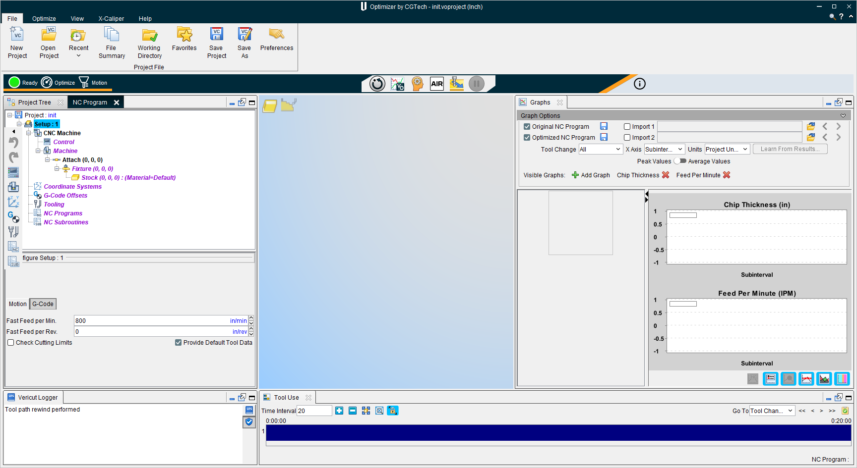
The Optimize group command buttons control Optimization processes and correspond to icons in the Status Bar.
Learn From NC Program — Opens the Learn from NC Program window enabling you to set the parameters for how the program should run.
Optimize — Opens the Optimize window enabling you to set the parameters for how the program should run.
Air Cuts — Opens the Air Cuts window enabling you to set the parameters for how the program should run.
Analyze NC Program — The Analyze button is used to activate the feature of the same name. This turns Optimization "On" and runs through machining process to gauge the forces used in machining. Force calculations are done but no optimized NC program is generated. This enables you to run Force and review the Graphs that are generated to determine appropriate values to use. At end of Optimization, a Graph can be viewed showing the forces that were used and what they were optimized to.
Compare Files — The Compare Files button is used to open the Compare NC Program Files window enabling you to select and compare the original NC program file and the optimized NC program file.
Savings Calculator — This button opens the Savings Calculator window, enabling you to enter shop specific information and use the information available from using the Optimization feature to optimize the current part to calculate the both the part savings, and the workshop savings associated with using Optimization.
Graphs — The Graphs button opens the Graphs window enabling you to learn various tool information about your simulation.
Tool Use — This button opens the Tool Use graph which shows the machining time, in minutes, spent by each simulated tool. The text displayed to the left of the graph line(s) is the sub-system ID. Each tool that cuts the part is shown in the graph with its cut color. Tool changes are indicated by a spike in the graph line. Positioning the mouse cursor on or above a graph line displays data about that tool.
Compare Files — The Compare Files button is used to open the Compare NC Program Files window enabling you to select and compare the original NC program file and the optimized NC program file.
Savings Calculator — This button opens the Savings Calculator window enabling you to enter shop specific information and use the information available from using the Optimization feature to optimize the current part to calculate the both the part savings, and the workshop savings associated with using Optimization.
Tool Use — This button opens the Tool Use graph which shows the machining time, in minutes, spent by each simulated tool. The text displayed to the left of the graph line(s) is the sub-system ID. Each tool that cuts the part is shown in the graph with its cut color. Tool changes are indicated by a spike in the graph line. Positioning the mouse cursor on or above a graph line displays data about that tool.
Global group
Preferences — Opens the Preferences window enabling you to specify the project file that you want displayed when you start the next session, the number of "recent files" that you want Optimizer to remember, and the PDF reader/web browser that you want Optimizer to use for online Help.
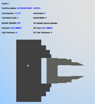
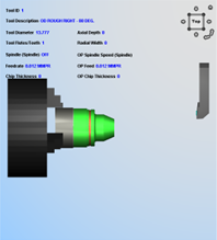
Profile/Workpiece — Use this button to toggle the Graphics Area view between displaying the Profile and the Workpiece view.
Profile
Workpiece
No Animation — Enables you to reduce processing time. When toggled "on" (checked), the graphics display is not updated until either processing is complete or you Stop the processing. At that time the cut model is displayed in it "final" state or the state that it was in when processing was stopped.
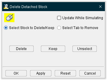
Delete Detached Stock — opens the Delete Detached Stock window enabling you to delete or keep pieces of material. This feature is typically used to delete pieces of excess stock that have been cut free from the workpiece. However, pieces of other models can also be deleted.
-
 (Down to enable mouse tracking and picks, up to disable.) — Use this icon to designate that the Delete Detached Stock window is the window that picks in the Vericut graphics area are to be applied to. When toggled “on”, the icon is displayed in the Mouse Pick Highlight Color specified in the Configuration tab > Preferences window.
 -
Update While Simulating — When toggled "On", Vericut checks during the simulation for detached material based on the stock's relationship to all parent fixture models. The Stock must be a Child of a Fixture component.
-
Select Stock/Tab to Remove — Use this feature to remove stock or tabs left on the machined part (used for holding the part during the machining process) from a model.
-
Delete — After selecting the items to be deleted (they will be highlighted), click Delete to remove selected items from all views. Click OK, described above, to permanently delete the items.
-
Keep — After selecting the items to keep (they will be highlighted), click Keep to remove all un-selected items (not highlighted) from all views. Click OK, described above, to permanently delete the items.
-
Unselect — Use this feature any time while selecting items for Delete/Keep to un-select all selected items (they will no longer be highlighted). This feature becomes inactive once you click on Delete/Keep.
-
OK — Use this feature to permanently delete the items selected for Delete/Keep, or activate Update while Simulating and close the Delete Material window.
-
Apply — Permanently deletes the stock without closing the window.
-
Reset — Puts the deleted stock back in place so long as OK or Apply have not been clicked. Clicking OK or Apply permanently deletes the stock and it cannot be replaced after that.
-
Cancel — Use to un-select all items, cancel any Delete/Keep action, and close the Delete Material window.
Save Cut Stock — opens the Save Cut Stock window enabling you to save the selected Cut Stock model as a Vericut Solid file (.vct). This option is only active after a Cut Stock model has been created by Vericut. The default file extension is .vct.
View tab
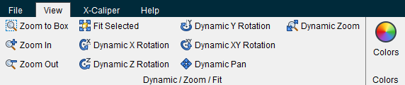
Dynamic/Zoom/Fit group
Zoom to Box — After selecting, you will use your mouse to click and drag a selection box in the Graphics Area. The view will then zoom into the area defined by the box you made.
Zoom In — Magnifies the current images in the Graphics Area by about 10%.
Zoom Out — Reduces the size of the current images in the Graphics Area by about 10%
Fit Selected — Zooms in or out as appropriate until the images in the Graphics Area take up the full space of the window as much as possible.
Dynamic X Rotation — When active, enables you to rotate images along the X axis by clicking and dragging in the Graphics Area.
Dynamic Z Rotation — When active, enables you to rotate images along the Z axis by clicking and dragging in the Graphics Area.
Dynamic Y Rotation — When active, enables you to rotate images along the Y axis by clicking and dragging in the Graphics Area.
Dynamic XY Rotation — When active, enables you to rotate images along the XX axis by clicking and dragging in the Graphics Area.
Dynamic Pan — When active, enables you to move images up, down, left, and right by clicking and dragging in the Graphics Area.
Dynamic Zoom — Enables you to zoom in and out as needed by clicking in the Graphics Area. The same functionality can be achieved by using the mouse wheel. Scrolling up will zoom in and scrolling down will zoom out.
Colors group
Colors — Opens the Color window enabling you assign colors to various displays throughout the VO software.
X-Caliper tab

Feature/History — displays related cut feature (mathematical description) and NC program history. The historical data includes: NC program file name, record number, and NC program record text responsible for cutting the feature. This function is useful to spot-check machined features, and determine the source of an error cut or additive bead placement identified in red.
Model Thickness — used to measure stock material thickness. Maneuver the measurement arrow until you have found your desired surface and click on that surface to select it. Once the surface is selected, the measurement appears as a Dimension label floating above where the measurement was taken.
Air Distance — used to measure the air gap between two solid surfaces. Select Air distance and then click on a surface in the View window to measure. A measurement line will form showing the two solid surfaces that were measured between.
Plane to Point — enables you to select a plane and point on a material to analyze the distance between them. Once the command button is active, first click on a plane in the graphical display. Notice that a blue arrow will point outwards from the plane you are selecting, helping you to make certain you are selecting the right plane. Second, click on a point you wish to measure from the plane. Once the point is selected, the measurement arrow is displayed at the location of the point.
Plane Angle — enables you to select two points on a material to analyze the angle between them. Once the command button is active, click in the graphical display on the first point and the second point you wish to measure between. Notice that a blue arrow will point outwards from the plane you are selecting, helping you to make certain you are selecting the right plane.
Axis to Axis — enables you to select two points on a material to analyze the distance between parallel holes. Once the command button is active, click in the graphical display on the first point and the second point you wish to measure between. Notice that a blue arrow will point outwards from the center of the hole you are selecting, helping you to make certain you are selecting the right plane.
Diameter/Radius — enables you to select any point on the wall of a cylinder or hole to analyze the distance from that point to the opposite end wall of the cylinder or hole. Once the command button is active, click in the graphical display on the point you wish to measure from. Notice that a blue arrow will point outwards from the selection point towards the wall it will be measuring towards, helping you to make certain you are selecting the right plane.
From/To — Each group includes the Feature, Location and Direction used to specify what to measure from and what to measure to. Use the From / To arrows  , to control which fields are filled in by screen pick data. You can select features on the Vericut model, or enter number values (separated by blank spaces) directly into the fields in the Settings group. After selecting the From feature, Vericut automatically transfers control to the To group. After selecting the To feature the Vericut Logger panel displays the measurement data.
 Feature dropdown menu — Controls the types of features to measure between. Select the Feature type from the pull-down list. The default feature is Point until a new feature is selected.
Feature descriptions:
-
Point — The X, Y, Z of the pick point or entered point coordinates.
-
Plane — A flat, unbounded surface. If a curved surface is selected, data retrieved represents a plane tangent to the selected model surface at the pick point.
-
Axis — Centerline of a cylinder or conic.
-
Edge — Edge formed by two intersecting planes or parallel cylinders. Special cases follow.
-
Vertex — Enables you to easily select one of the six key points associated with the triangles representing the faces of a model. For each triangle, the points consist of the three vertices and the midpoint of each of the triangle's three sides. Vericut selects the point closest to your mouse pick. If the mouse pick is over the cut stock, Vertex works in the same way as the Point feature described above. Vertex is a useful tool for measuring the trace of tool/fixture collisions on uncut fixtures.
-
Model Origin — Origin of a selected model. Use the Project tab > Axes to see model origin axes.
-
Component Origin — Origin of a selected component. Use the Project tab > Axes to see component origin axes.
-
CSYS Origin — Origin of the selected coordinate system axis. Use the Project tab > Axes to display the coordinate systems that are available.
-
CSYS Axis — The X, Y, or Z axis of the selected coordinate system. Use the Project tab > Axes to display the coordinate systems that are available.
-
Circle Center — Use this feature to specify a circle center point to be used as a From or To feature.
-
Choose Circle Center from the pull-down list, and then click the arrow
to enable selecting geometry in the graphics area. -
Follow the prompts in the temporary message area above the Vericut Logger panel to define the circle center point.
- Pick the XY plane of the circle.
- Pick the cylinder/cone face that contains the circle.
-
The circle center point will display in the graphics area and the coordinates of the center point will display in the Location text field in the Vericut Logger panel.
-
Toolpath Trace — Use this feature to specify the toolpath you would like to take measurements from. This feature is only available when NC Program Review is active.
These buttons are used together to measure the depth of a hole, the depth of a countersink or the depth of a counterbore.
Hole Top — This is the feature that defines the top of the hole (generally a plane).
Hole Bottom — This is the feature that defines the bottom of the hole.
Feature — Use to specify the feature that you want to measure.
Once all three buttons have been used to define the hole, the Settings group will update to display info about your measurements.
These buttons are used together to measure the tops and bottoms of features as well as the C-Sink depth.
Top Feature — This is used to define the top of a C-Sink.
Bottom Feature — This is used to define the bottom of a C-Sink.
C-Sink — This is used to measure the depth of a feature. It is similar to Hole Depth but measures only as far down as the specified Bottom Feature rather than measuring the entire depth of the hole.
Once all three buttons have been used to define the hole, the Settings group will update to display info about your measurements.
These buttons are used to measure the point in which two axes intersect and the distance from this point to an intersecting plane along those axes.
First Axis — This is used to define one axis of the intersection.
Second Axis — This is used to define the other axis of the intersection.
Intersecting Plane — This is used to define a plane that intersects one or both axes to measure the distance from the axis-axis intersection point to the axis-plane intersection point along the axis.
Once all three buttons have been used to define the hole, the Settings group will update to display info about your measurements.
Center of Gravity — Reports X Y Z values of the calculated center of gravity point for the current cut stock model. If multiple cut stock models exist, user is prompted to select one.
Highlight Plane/Cylinder — The Highlight Plane/Cylinder command button enables you to select a plane and have Vericut highlight all "cut" features that lie in the same plane. It also enables you to select a cylinder and Vericut will highlight all cylinders that have the same radius within the specified tolerance. Select Highlight Plane/Cylinder and then select any plane or cylinder on the stock workpiece in the Workpiece view window.
Closest Point — The Closest Point command button is used to measure the shortest distance from an XYZ point location to the closest point on the model surface. In order to use the Closest Point option, Closest Point must be selected and then the XYZ coordinates of the “From” point must be entered into the Location text field in the Settings group.
Volume — The Volume command button calculates and displays the following volume values for a selected stock workpiece: current cut stock volume, original stock model volume, and volume of material removed from the original stock model. All volumes are in cubic units.
Scallop — The command buttons in the Scallop group are used to measure the height of a scallop formed by two parallel intersecting cylinders. Select the two parallel and intersecting cylinders on the Vericut model that form the scallop. X-Caliper identifies the cylinders being measured by displaying intersecting circles on the model.
The Settings section is a dynamic section that updates depending on what features and options are selected from other X-Caliper sections. The default section is shown below:

The most common sections that appear in this group are the Location and Direction fields. When these features are present in the Settings group, they are editable text fields. Location tells you the CSYS of where you clicked on the stock you are measuring and Direction indicates which axis the feature is measuring along. For instance, when using Model Thickness a Direction of 0 -1 0 would indicate that thickness is being measured downward along the Y axis.
Options:
 (Inch) — Specifies that measurements be displayed in inches. Click on the icon to change it to:
 (Millimeter) — Specifies that measurements be displayed in millimeters. Click on the icon to change it back to .
Help tab
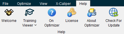
Welcome — Opens the Welcome Screen.
Training Viewer — Opens the Training Viewer panel.
On Optimizer — opens this Help.
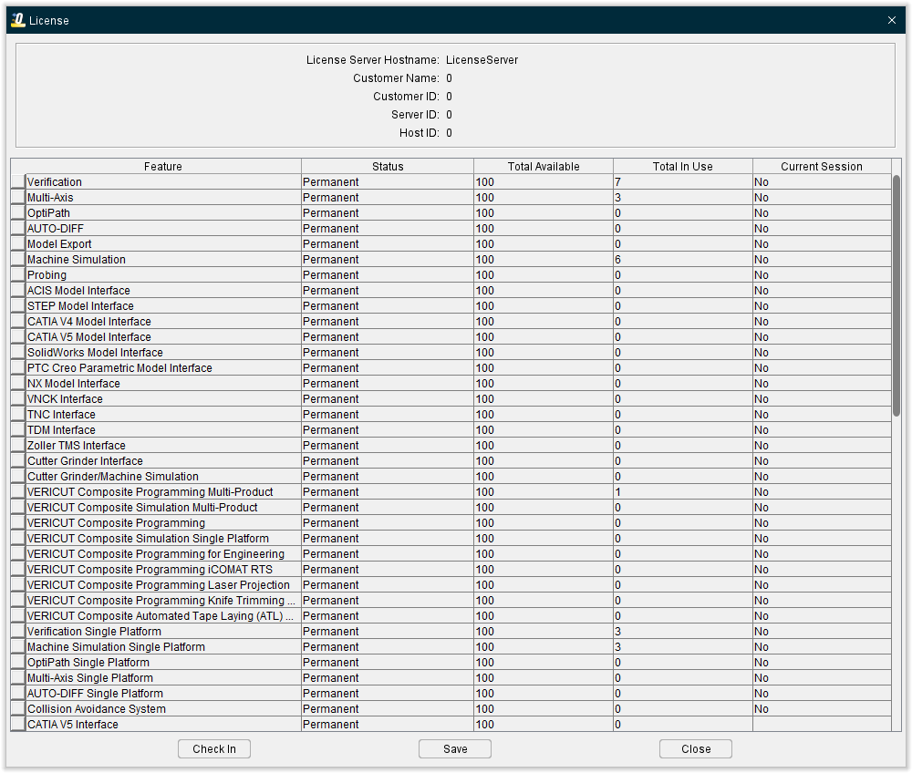
License — opens a window which displays all available licenses for use.
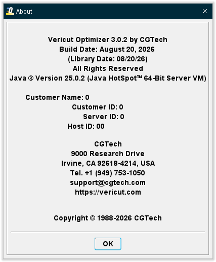
About Optimizer — opens a window telling you various information about your Optimizer download including current version, most recent build date, and so on.
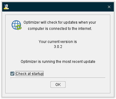
Check For Update — will verify if there is a newer version of Optimizer available for download. Toggle on Check at startup to have this check run automatically whenever this software is opened.