Using the Tool Manager
Tool List Area
The Tool List Area of the Tool Manager window contains a list of all tool assemblies and the components that make up each tool assembly for all of the tools contained in the current tool library file. The Tool List Area provides a list of the tools/tool assemblies contained in the Tool Library. Each tool/tool assembly has a unique alpha-numeric text identifier (ID).
IDs typically correspond to tool or pocket numbers referenced by the tool change record that will call the tool from the library. For example, ID " " would normally be used for a tool called by a G-Code data block "T1M6", or an APT tool change record "LOADTL/1". However, you can use a tool list to cross-reference tools having IDs in a library that are different from those in the tool change record.
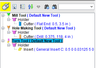
 (Mouse Tracking) — When active, the icon will be highlighted yellow. This means that you will be able to click a feature in the Tool Display Area and the corresponding feature will be selected in the Tool List Area.
 (Expand/Collapse the Csys Window) — Click on the Expand/Collapse the Csys Window icon to hide the Coordinate Systems area from being displayed in the Tool Manager window. Click on the Expand/Collapse the Csys Window icon again to re-display the Coordinate Systems area in the Tool Manager window.
 (Expand/Collapse All Tool Components) — Click on the Expand/Collapse All Tool Components icon to display the tool components in the Tool List. Click on the Expand/Collapse All Tool Components icon again to remove the display of tool components in the Tool List.
 (Sort by Tool ID) — Use this feature to sort the tools in the Tool List Area.
Click on the Sort by Tool ID) icon to list the tools in the Tool List Area by Tool ID from lowest to highest. Click on the Sort by Tool ID) icon again to list the tools in the Tool List Area in the reverse order.
Click on the  to display a menu with the following options.
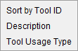
Sort by Tool ID — This feature provides the same functionality described above for the Sort icon.
Select Sort by Tool ID to list the tools in the Tool List Area by Tool ID from lowest to highest. Select Sort by Tool ID again to list the tools in the Tool List Area by Tool ID in the reverse order.
Description — Use this feature to sort the tools in the Tool List Area by the tool descriptions.
Select Description to list the tools in the Tool List Area by description. Select Description again to list the tools in the Tool List Area in the reverse order.
Tool Usage Type — Use this feature to sort the tools in the Tool List Area by the tool usage type (Mill, Hole Making, Turn, Probe, etc.).
Select Tool Usage Type to list the tools in the Tool List Area by tool usage type. Select Tool Usage Type again to list the tools in the Tool List Area in the reverse order.
 Search Forward — Searches forward in the Tool List for the text string specified in the Search Text field.
 Search Backward — Searches backward in the NC program listing for the text string specified in the Search Text field.
Tools
Tool Library files contain descriptions of cutting tools, or tool assemblies. Tool Library data is used by Optimizer when a setup’s Tooling Branch in the Project Tree is configured to do so. Use the procedures below to add new tools to a Tool Library.
📝 NOTE: Remember to save the Tool Library file with the modified tool information when you finish.
The following tool types are valid in a tool library file:
 Mill Tool — Mill tools can have one, or more, of the following Tool Components associated with it: Insert Cutters, Revolved Cutters, and Holders. Mill tools can also have one, or more, of the following tool related records associated with it: Optimization, Driven Point, and Cutter Compensation.
 Hole Making — Hole Making tools can have one, or more, of the following Tool Components associated with it: Revolved Cutters, Insert Cutters, and Holders. Hole Making tools can also have one, or more, of the following tool related records associated with it: Driven Point, and Cutter Compensation.
 Turn Tool — Turn tools can have one, or more, of the following Tool Components associated with it: Insert Cutters and Holders. Turn tools can also have one, or more, of the following tool related records associated with it: Driven Point, and Cutter Compensation.
Add a Tool, Specify Tool Related Information
-
In the Tool List Area, select the tool that you want the new tool assembly added after so that it becomes highlighted.
-
In the Tool Manager Tool Bar, click on command buttons of the Add group to select the type of tool assembly that you want to add from the list.
Similarly you can specify the type of tool assembly that you want to add by right clicking in the Tool List Area and using the Add Tool feature in the menu that displays.
-
When the tool assembly is added, Optimzer creates a default tool ID but you can change it by right-clicking on the tool in the Tool List Area and select Rename from the menu that displays. Modify the tool ID as desired.
-
When the tool assembly is added, the Tool Information tab automatically displays in the center of the Tool Manager window enabling you to specify tool information like Description, Units, Gage Point, Driven Point, Cutter Compensation, etc. Use these features to define the information for the tool that you just added.
-
If you just created a tool assembly as described in the Add a Tool, Specify Tool Related Information, click on the holder component in the Tool List Area so that it becomes highlighted. The appropriate Tool Definition window should now be displayed in the center of the Tool Manager window.
-
In the Tool Definition window, select the Tool Component tab.
- Select the appropriate holder shape/type icon for the holder. Placing the cursor over an icon displays a description of the kind of holder that the icon represents. After selecting the icon the lower part of the tab will update to display the features appropriate for the chosen holder shape.
- Enter supporting data to describe the holder. Press the Enter key after adding a parameter to see the affect it has on the holder.
If the added component is larger than the display area, right-click in the Tool Manager's Tool Display Area and select Fit in the menu that displays to see the entire tool assembly.
-
Toggle the Use as Shank option on (checked) if using holder as a shank. If this option is toggled on (checked), Do Not Spin with Spindle and Alternate features will be disabled.
-
If desired, choose a Color for the holder. Components in a tool assembly have the option to "Inherit", or override, the Tool component's defined color.
- Toggle Do Not Spin with Spindle on (checked) or off (not checked) to specify whether or not the holder should spin with the spindle.
- Toggle Alternate on (checked) or off (not checked) to specify whether or not the holder is an "alternate" or "secondary" holder.
- Click on the Assembly tab. Use the features on the Translate and Rotate tabs to translate or rotate the Holder to the correct position in the tool assembly. You can also use the features on the Assemble tab to position the holder by assembling (mating or aligning) it with other objects in the tool assembly.
📝 NOTE: The above steps can also be used to define additional tool holder components or used to modify existing tool holder components.
Tool Components
 Insert Cutter — Insert Cutters can be either mill inserts for Milling Tools or turn inserts for Turn Tools.
 Revolved Cutter — Revolved Cutters are tools like end mills.
 Hole Making Tool — Hole Making Tool components are tools like drills, reamers, center drills and taps.
 Holder — Holder components are used to define a tool holder or the components of a tool holder assembly.
Define Tool Components
-
If you just created a tool assembly as described in the Add a Tool, Specify Tool Related Information section, click on the cutter component in the Tool List Area so that it becomes highlighted. The appropriate Tool Definition window should now be displayed in the center of the Tool Manager window.
-
In the Tool Definition window, select the Tool Component tab.
- On the Tool Component tab, select the appropriate shape/type icon for the hole making cutter that you are defining. Placing the cursor over an icon displays a description of the kind of cutter that the icon represents. After selecting the icon the lower part of the tab will update to display the features appropriate for defining the chosen cutter shape.
- Enter the supporting data to describe the Cutter or Insert. Press the Enter key after adding a parameter to see the affect it has on the insert.
If the added component is larger than the display area, right-click in the Tool Manager's Tool Display Area and select Fit in the menu that displays to see the entire tool assembly.
-
If desired, choose a Color for the holder. Components in a tool assembly have the option to "Inherit", or override, the Tool component's defined color.
-
If desired, choose a Shank Color for the holder.
- Specify the Spindle Direction. Choose either CW (clockwise) or CCW (counter clockwise.
- Toggle Alternate on (checked) or off (not checked) to specify whether or not the cutter is an "alternate" or "secondary" cutter.
- Toggle OK to Mill on (checked) or off (not checked) to specify whether or not to override the default check for axial cuts enabling you to machine with a Hole Making Tool other than along the tool axis. For example, using a drill to create a chamfer.
- Click on the Assembly tab. Use the features on the Translate and Rotate tabs to translate or rotate the cutter to the correct position in the tool assembly. You can also use the features on the Assemble tab to position the cutter by assembling (mating or aligning) it with other objects in the tool assembly.
📝 NOTE: The above steps can also be used to modify existing tool components.
All of the following procedures apply to the tool record that is currently highlighted in the Tool Manager, Tool List Area and the Tool Manager, Tool Information tab has been automatically displayed in the center of the Tool Manager window enabling you to specify a variety of tool information.
To enter a gage offset for a tool used in a G-Code NC program simulation —
In the Tool Manager, Tool Information tab, click in the Gage Point field so that it becomes highlighted, and then enter data in the field, or use Tool Manager's Tool Display Area to select a position on the tool assembly to supply the gage offset values. Note that selecting gage offset points with the left mouse button supplies 3-dimensional offset data, however, milling tool gage offsets typically should only have a "Z" value, for example: 0 0 6.5. Selecting the gage offset point with the center mouse button will only update the "Z" value.
To orient the tool in a direction other than defined —
In the Tool Manager, Tool Information tab, click in the Orientation field so that it becomes highlighted, then enter X, Y, and Z rotation angle values (separated by spaces) to orient the tool assembly relative to the tool origin. Angle values are in degrees, relative to the tool origin. Rotation occurs about the tool's gage point.
To move the tool control point (driven point) —
-
In the Tool Manager, Tool Information tab, click on the Driven Point
 icon to add a driven point record to the Driven Point table.
 -
Optimizer adds a default ID but you can change it by clicking in the ID field of the driven point record and enter another ID for the driven point record. Click in the Value field of the driven point record and enter the coordinates of the driven point, or use Tool Manager's Tool Display Area to select a position on the tool assembly to supply the driven point values.
📝 NOTE: You can remove a driven point record from the Driven Point table by clicking on the record so that it becomes highlighted and then click on the  icon to remove the record.
To add a cutter compensation value —
-
In the Tool Manager, Tool Information tab, click on the Cutter Compensation
 icon to add a cutter compensation point record to the Cutter Compensation table.
 -
Optimizer adds a default ID but you can change it by clicking in the ID field of the cutter compensation record and enter another ID for the driven point record. Click in the Value field of the cutter compensation record and enter the cutter compensation value
📝 NOTE: You can remove a cutter compensation record from the Cutter Compensation table by clicking on the record so that it becomes highlighted and then click on the icon to remove the record.
Tool Related Records
 Stock Material Record — Used by Optimizer to determine how to optimize feed rates and/or spindle speeds for the specific tool under various cutting conditions. Both “active” and “inactive” Stock Material records for a particular tool are displayed in the Tool Table. The “active” or “inactive” state is determined by the Material and Machine settings on the Optimize window.
 Active Stock Material Record — When the Material and Machine values for a particular Stock Material record in the Tool List Area, both match the Material and Machine settings on the Optimize window, Optimization Settings tab, the Stock Material record is considered to be “active”. Active Stock Material records are identified by colored symbols.
 Inactive Stock Material Record — When the Material and Machine values for a particular Stock Material record in the Tool List Area, do not both match the Material and Machine settings on the Optimize window, Optimization Settings tab, the Stock Material record to be considered “inactive”. Inactive Stock Material records are identified by gray symbols.
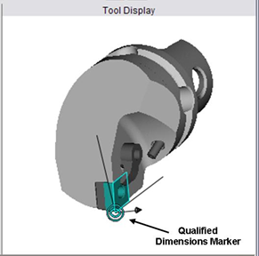
 Qualified Dimensions Record — These are needed when cutting face of a CAD insert is far away from the machine component ZX plane. Having QD defined might improve accurate material removal. As in this and your pictures, you can see a tilted cutting face from the ideal ZX cutting plan.
↘️ Shortcut: s:
-
Double click a tool component in the Tool List Area to display the Tool Component tab to enable modification of the tool component.
-
Right-click in the Tool List Area to display a menu with the following features. The features that are available will vary slightly depending on the item that is highlighted.
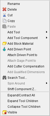
Rename — Use to rename the highlighted object in the Tool List Area.
Delete — Deletes the highlighted object from the Tool List Area.
Cut — Cuts the highlighted object in the Tool List Area and puts it in the paste buffer.
Copy — Copies the highlighted o in the Project Tree to the paste buffer.
Paste — Puts the contents of the paste buffer after the highlighted object in the Tool List Area. The Paste feature only becomes active after the Cut or Copy feature has been used.
Add Tool — Use to add a new tool assembly to the Tool List Area. Select the tool type from the menu that displays. Optimizer will add a unique Tool ID but you can change it if you wish.
Mill — Adds a Mill Tool tool assembly after the highlighted tool in the Tool List and displays the Tool Component tab for Mill Tools enabling you to define the tool component in the new tool assembly.
Hole Making — Adds a Hole Making Tool tool assembly after the highlighted tool in the Tool List and displays the Tool Component tab for Hole Making Tools enabling you to define the tool component in the new tool assembly.
Turn — Adds a Turning Tool tool assembly after the highlighted tool in the Tool List and displays the Tool Component tab for Turn Inserts enabling you to define the tool insert in the new tool assembly.
Standard Hole Making — Adds a Standard Hole Making Tool tool assembly after the highlighted tool in the Tool List and displays the Tool Component tab for Polisher tools enabling you to define the polisher tool in the new tool assembly.
DXF Tool — Displays the DXF Geometry window.
CAD Tool — Displays the Import CAD Tool window.
Add Tool Component — Use to add a new tool component to an existing tool in the Tool List Area. Select the component type from the menu that displays.
Holder — Adds a Holder component to the highlighted Tool and displays the Tool Component tab for Holders enabling you to define the new holder component.
Cutter — Adds a Cutter component to the highlighted Tool and displays the appropriate Tool Component tab enabling you to define the cutter.
Add Stock Material — Displays the Stock Material Record window.
Add Driven Point — Displays the Tool Information tab enabling you to add one or more a Driven Point records for the highlighted tool.
Add Cutter Compensation — Displays the Tool Information tab enabling you to add one or more Cutter Compensation records for the highlighted tool.
Add Qualified Dimensions — The Qualified Dimension record is added to the tool assembly in the Tool List Area as shown in the picture below. Holding the cursor over the Qualified Dimensions record will display a tip with the current values of the record as shown in the picture below.
Click on the turning tool so that it becomes highlighted. Then select Add menu > Qualified Dimensions to add a Qualified Dimensions record to the tool as shown in the picture below.
You can also right-click on the turning tool so that it becomes highlighted and then select Add Qualified Dimensions in the menu that displays to add the Qualified Dimensions record.
The Qualified Dimension record is added to the tool assembly in the Tool List Area as shown in the picture below. Holding the cursor over the Qualified Dimensions record will display a tip with the current values of the record as shown in the picture below.
The qualified dimension and driven point location are often coincident. When adding a Qualified Dimension record, it will default to the same 3 values as the first driven point if one exists. When adding the first driven point it will default to the same 3 values as the Qualified Dimension if one exists.
The Qualified Dimension can be modified as need by editing the values in the Description column of the Qualified Dimensions record.
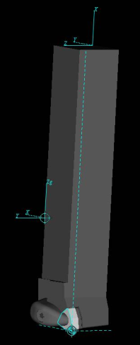
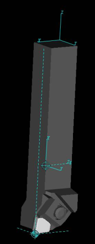
When a Qualified Dimension Record is added a turning plane is also created. The turning plane defaults to the ZX plane of the “orientation” of the tool (how it is mounted in the tool component). When orientation is 0,0,0, then it is the same as the ZX plane of the tool origin. The turning plane direction is indicated to be the Y-axis of the tool orientation axis by the presence of a Y in the Units column of the Qualified Dimensions record. Another axis can be specified by selecting the desired axis from the pull-down list in the Units column.
Examples
| For the tool in the picture below, the X-Y plane goes through the Qualified Dimensions point, and the cutting plane direction will be along the tool’s Z-axis. | For the tool in the picture below, the X-Z plane goes through the Qualified Dimensions point, and the cutting plane direction will be along the tool’s Y-axis. |
|---|---|
 |
 |
Spin Around — The Spin Around feature is only available for inserted tools. It enables you to specify whether to spin the tool around the Tool Axis (for example a right angle holder), or around the Machine Spindle axis.
Shift Component Z — The Shift Component Z feature displays the Z Offset window enabling you to specify an offset value for moving the highlighted tool component in the Z direction.
The Shift Component Z feature is not available under the following conditions:
- The highlighted tool component is part of a Turn tool assembly.
- When the highlighted item is an Stock Material record.
Expand/Contract All — Click on this feature to Expand (display all tool components) for all Tools in the Tool List Area. Click on it again to Contract (not display all tool components) for all Tools in the Tool List Area.
Show Tool Components — Use this feature to show all tool components for the highlighted tool in the Tool List Area.
Hide Tool Components — Use this feature to hide all tool components for the highlighted tool in the Tool List Area.
Visible — Use this to set the visibility of the Tool component.
Invisible — Use this to make several Tool components invisible at once. This feature is only available when multiple components are selected in the Tool List Area.
Z Offset window
The Z Offset window, accessed from the Tool Manager: Tool List Area right mouse button menu: Shift Component Z feature, enables you to specify an offset value for shifting the highlighted tool component in the Z direction.
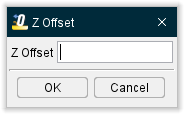
Z Offset — Use to specify an offset distance for shifting the tool component in the Z direction. Enter the offset distance in the Z Offset text field.
OK — Use OK to apply the specified Z offset distance and close the Z Offset window.
Close — Use to close the Z Offset window without applying the specified Z offset distance.
Coordinate System List Area
The features in the Coordinate Systems List Area enable you to create and modify coordinate systems that can be used to orient tools and tool assemblies from within the Tool Manager.
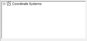
The Coordinate Systems area, located below the Tool List Area and above the Message area, is initially displayed empty as shown in the picture below.
Once one or more coordinate systems are added, the Coordinate System area changes so that it is displayed in the following picture.
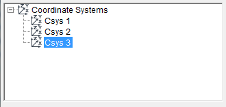
The Coordinate System area shows a list of all of the coordinate systems that have been created in Tool Manager.
Add a New Coordinate System:
-
Right-click in the Coordinate Systems List Area and select Add New CSYS from the menu that displays. A new coordinate system will be added to the Coordinate Systems List Area of the Tool Manager, and the Configure Coordinate System window will display in the center of the Tool Manager window enabling you to define the coordinate system.
-
Right-click on the default coordinate system name and select Rename in the menu that displays to rename the coordinate system.
- Use the features on the Configure Coordinate System window’s tabs to position and orient the newly created coordinate system.
- Select Add New CSYS in the Configure Coordinate System menu to add addition coordinate systems.
Any changes made on any of the Configure Coordinate System window’s tabs are applied to the coordinate system that is highlighted in the Tool Manager Coordinate Systems List Area. You can also use the Configure Coordinate System window to modify existing coordinate systems.
Add a New Coordinate System From a File:
- Right-click in the Coordinate Systems List Area and select CSYS from File from the menu that displays.
A file selection window will display enabling you to specify the CSYS file to be used.
-
Once you select the CSYS file and press OK in the file selection box, a new coordinate system is added to the Coordinate Systems List Area of Tool Manager, and the Configure Coordinate System window will display in the center of the Tool Manager window enabling you to modify the coordinate system or create additional coordinate systems.
-
Right-click on the coordinate system name and select Rename in the menu that displays to rename the coordinate system.
Any changes made on any of the Configure Coordinate System window’s tabs are applied to the coordinate system that is highlighted in the Tool Manager Coordinate Systems List Area. You can also use the Configure Coordinate System window to modify existing coordinate systems.
↘️ Shortcut:
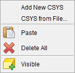
Right-click in the Coordinate System List area that has no coordinate systems defined to display a menu with the following features:
Right-click in the Coordinate System List area that has one or more coordinate systems defined to display a menu with the following features:
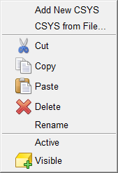
Add New CSYS — Adds a new CSYS to the Tool Manager, Coordinate Systems list. Optimizer automatically provides a unique name for the CSYS. You can right-click on the default name and select Rename from the menu that displays to rename the CSYS if desired.
New coordinate systems are created with zero translation and rotation values and attached to the Tool origin. The newly added coordinate system is automatically selected in the Coordinate Systems list. Use the Configure Coordinate System menu to make any necessary modifications to the newly added CSYS.
CSYS from File — Displays a file selection box enabling you to specify the CSYS file to be used. Optimizer will read the file and creates a CSYS attached to the selected tool.
Cut — Cuts the highlighted coordinate system in the Coordinate System list and puts it in the paste buffer.
Copy — Copies the highlighted coordinate system in the Coordinate System list to the paste buffer.
Paste — Puts the contents of the paste buffer after the highlighted coordinate system in the Coordinate System list.
Delete — Deletes the highlighted coordinate system from the Coordinate System list.
Rename — Use to rename the highlighted setup.
Visible — Use to make the highlighted coordinate system from the Coordinate System list visible, or not visible in the Tool Manager, Tool Display area. The Visible icon will indicate the visibility status of the coordinate system.  indicates "visible",
  indicates "not visible". Click on Visible to toggle between the two modes.
Tool Display Area
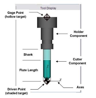
The Tool Display Area displays the tool selected in the Tool List. Colors distinguish holders from cutter components. Target symbols indicate the tool's driven point and gage point. Use the View Orient functions to visually manipulate the tool in the display area.
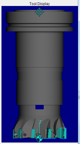
Milling Tool
CAD/STL Insert Turning Tool
↘️ Shortcut: s:
-
Double click a tool component in the Tool Display area to display the appropriate Tool Component tab enabling you to make modifications to the tool component.
-
Right-click in the Tool Manager Tool Display area to display a menu with the following features:
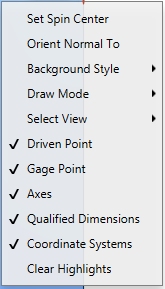
Select View — Select the view that you want from the pull-down list and the tool in the Tool Display area will re-orient to the selected view.
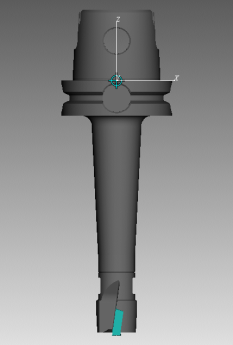
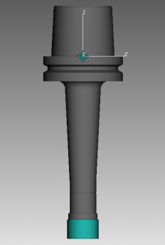
Spun Tool Display — When this option is toggled on (checked), tools in the Tool Display Area will appear as they would when they are in use. This feature will remain active until it is toggled off (unchecked) or until you exit Optimizer. Spun Tool Display is off by default at the start of each session.
| Standard view | Spun Tool Display active |
|---|---|
 |
 |
Orient Normal To — Resets the view to the normal of the feature selected in the graphics area. The modified view is centered on the position of the selection vector.
Background Style — Controls the background seen in a view.
Flat — Monochromatic.
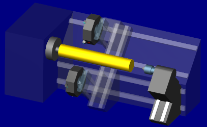
Shaded — Light-to-dark shading.
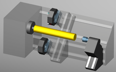
↘️ Shortcut: You can quickly change the Background Style by right-clicking in the view, and selecting Background Style from the displayed menu.
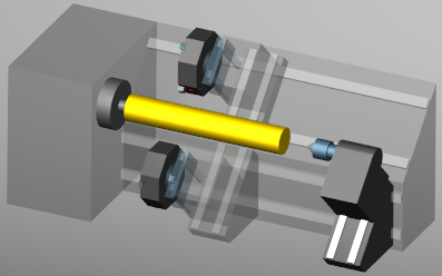
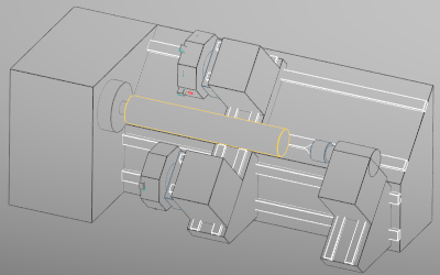
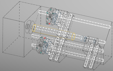
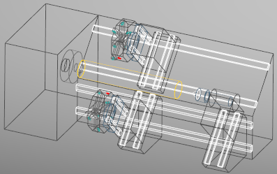
Draw Mode — Controls how machine components are displayed.
Shaded with Edges —
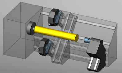
Shaded —
Hidden with Edges Removed —
Hidden Edges Shown —
Wireframe —
Polygon Wireframe —
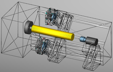
↘️ Shortcut: You can quickly change the Draw Mode by right-clicking in the view, and selecting from the displayed menu.
Select View — Orients the objects in the view to the selected view. The Select View feature list will contain all available standard and custom views.
Driven Point — Use to toggle the display of the driven point symbol  , which represents the location of the driven point, “on” (checked) and “off”.
Gage Point — Use to toggle the display of the gage point symbol  , which represents the location of the gage point, “on” (checked) and “off”.
Axes — Use to toggle the display of the axis, representing the tool origin, “on” (checked) and “off”.
Qualified Dimensions — Use to toggle the display of the qualified dimensions symbol  , which represents the qualified dimension location, “on” (checked) and “off”.
Coordinate Systems — Use to toggle the display of coordinate systems available in the Tool Manager, Coordinate Systems list, “on” (checked) and “off”.
Clear Highlights — Use to remove “highlights” from the Tool Display Area.
Example:
When using the X-Caliper features, if a tool component was created using a profile (Sweep Solid or Solid of Revolution) the profile will be displayed in the Tool Manager Tool Display area as shown in the picture below.
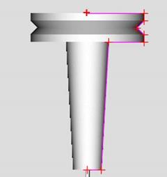
Use Clear Highlights to remove the profile when you are finished with it. The profile will automatically be removed when you change tool components.
Message Area
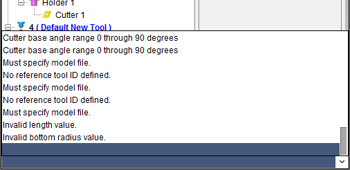
The message area, also known as the "message logger", is located at the bottom of the Tool Manager window, and by default displays the most recent message Optimizer has provided. Optimizer provides error, warning, and informational messages to assist you while working in the Tool Manager.
To review previous messages, click on the message line-the most recent message is listed last. Click again to close the message logger.