PTC Creo Parametric-to-Vericut Interface (PROEV)
Prerequisites
PROEV is a licensed software program that provides a Creo to Vericut data transfer connection. The interface is designed to work with Creo Parametric.
Versions supported:
PTC Creo Parametric 8.0 (or later)
CGTech Licensing:
PTC Creo Parametric Interface
Minimum Vericut Version required:
Vericut 7.2
Minimum Optimizer Version required:
1.1
Minimum Vericut License Version required:
9.4
Configuration
The CGTech software installation procedure places the files required by PROEV in a sub-folder. If you elected to install the software in the default folder " C:\Program Files\CGTech\Vericut x.x.x\windows64\proev
Steps
Copy the protk.dat file to the “start in” directory per the properties of the shortcut.
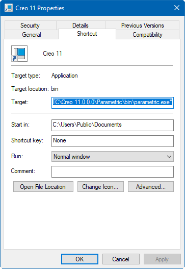
At startup, Creo Parametric will look for the registry file, protk.dat, to get location information about the other files used by the Creo-to-Vericut Interface. Creo Parametric will look for the protk.dat file first in the “start in” directory, then it will look in “
The protk.dat file contains the following information:
name cgtproev
startup dll
exec_file <full path, including the file name, where the cgtproev.dll is located>
text_dir <full directory path to the directory, where the proev.txt file is located>
revision Wildfire
end
Edit the protk.dat file to point to the locations of the cgtproev.dll and the proev.txt file.
The protk.dat file specifies the location of the cgtproev.dll file and the proev.txt file. Edit exec_file line so that it points to the \proev\Creoxx\cgtproev.dll of your Vericut installation.
Edit text_dir line so that it points to the \proev\Creoxx\text directory of your Vericut installation.
The protk.dat file should look similar to the following after editing:
name cgtproev
startup dll
exec_file C:\Program Files\CGTech\Vericut x.x.x\windows64\proev\Creoxx\cgtproev.dll
text_dir C:\Program Files\CGTech\Vericut x.x.x\windows64\proev\Creoxx\text
revision Wildfire
end
Environment variables
To enable Creo to find the necessary Vericut files, you also need to define three environment variables, CGTECH_INSTALL, CGTECH_PRODUCTS and LSHOST. CGTECH_SINGLE_PLATFORM and PROEV_LANGUAGE are optional.
| No. | Environment Variable | Example |
|---|---|---|
| 1 | CGTECH_INSTALL | C:\Program Files\CGTech\Vericut x.x.x |
| 2 | CGTECH_PRODUCTS | C:\Program Files\CGTech\Vericut x.x.x\windows64 |
| 3 | LSHOST | localhost |
| 4 | CGTECH_SINGLE_PLATFORM | YES |
| 5 | PROEV_LANGUAGE | C:\Program Files\CGTech\Vericut x.x.x\windows64\proev\Creoxx\ProevFrench.local |
| 6 | PROEV_PATH | C:\Program Files\CGTech\Vericut x.x.x\windows64\proev\Creoxx |
| 7 | CGTECH_VO_INSTALL | YES |
CGTECH_INSTALL is set to the Vericut installation folder. In the above table, x.x.x represents the Vericut release number. For a typical Vericut 9.7 installation this variable is set to C:\Program Files\CGTech\Vericut 9.7. Defining a value explicitly for the CGTECH_INSTALL environment variable is optional. It can be derived from the CGTECH_PRODUCTS environment variable value.
CGTECH_PRODUCTS is set to the folder for the specific operating system of the computer running Vericut: "windows64". In the above table, x.x.x represents the Vericut release number. For a typical Vericut 9.7 installation this variable is set to C:\Program Files\CGTech\Vericut 9.7\windows64.
LSHOST is set to the name of the license server computer.
CGTECH_SINGLE_PLATFORM=YES If you are using Vericut single Platform then an additional environment variable needs to be defined for the interface.
PROEV_LANGUAGE If you want the interface to use something other than US English, the variable can specify a file of localized text. Versions for French, German, Italian, Portuguese, Chinese and Japanese are supplied.
PROEV_PATH If you want to use a system variable to set the path to the exec_file and text_dir, set PROEV_PATH and call it in the protk.dat file.
Example:
name cgtproev
startup dll
exec_file $PROEV_PATH\cgtproev.dll
text_dir $PROEV_PATH\text
revision Wildfire
end
CGTECH_VO_INSTALL — if set to “yes” the Optimizer interface will start, otherwise it will be the Vericut interface. Note: One can also switch between the two using the radio buttons in the Options dialog.
Use the Microsoft Windows Control Panel > System Properties > Advanced tab > Environment Variables feature to define these environment variables. See Microsoft Windows Help for more information.
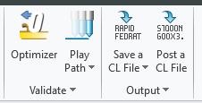
To add an icon to the Ribbon
The proev.txt file contains the resource text for the Vericut option which shows up in Pro/ENGINEER under the "Applications" menu. The Vericut option is the entry point for launching the Creo-to-Vericut Interface.
• Edit the proev.txt and set Vericut
Reference: C:\Program Files\CGTech\Vericut x.x.x\windows64\proev\Creox.x\text
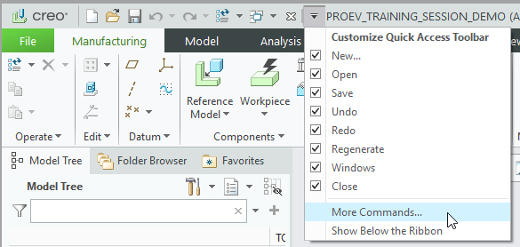
• Select Customize Quick Access Toolbar > More Commands..
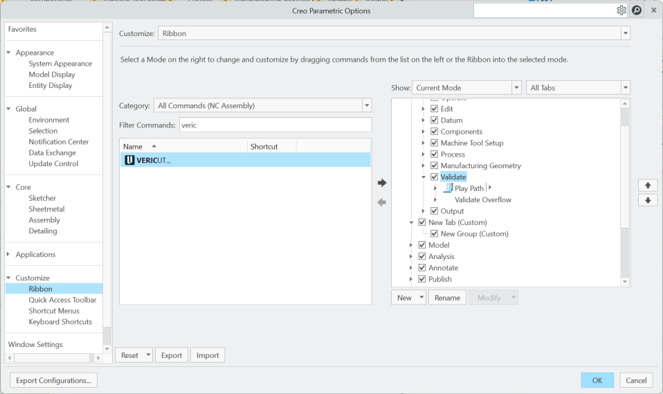
• Customize: Ribbon
• Category: All Commands (Note: you may need to set TOOLKIT Commands)
• Filter Commands: Vericut
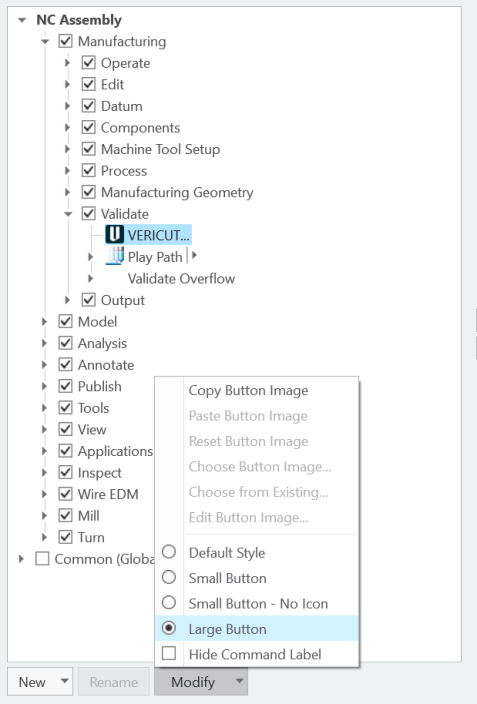
• Menu Validate
• Use  arrow to add Vericut to the desired location
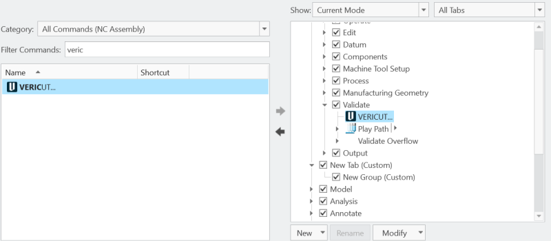
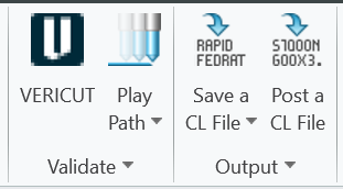
• Select Modify> Large Button
• Select Modify > Choose Button Image... and browse the Vericut32.gif
Reference: C:\Program Files\CGTech\Vericut x.x.x\windows64\proev\Creox.x\text\resource
• Select OK
To add the Optimizer Icon to the Creo Ribbon
• Edit the proev.txt and set Optimizer
Reference: C:\Program Files\CGTech\Vericut x.x.x\windows64\proev\Creox.x\text
• Select Customize Quick Access Toolbar > More Commands..
• Customize: Ribbon
• Category: All Commands (Note: you may need to set TOOLKIT Commands)
• Filter Commands: Optimizer
• Menu Validate
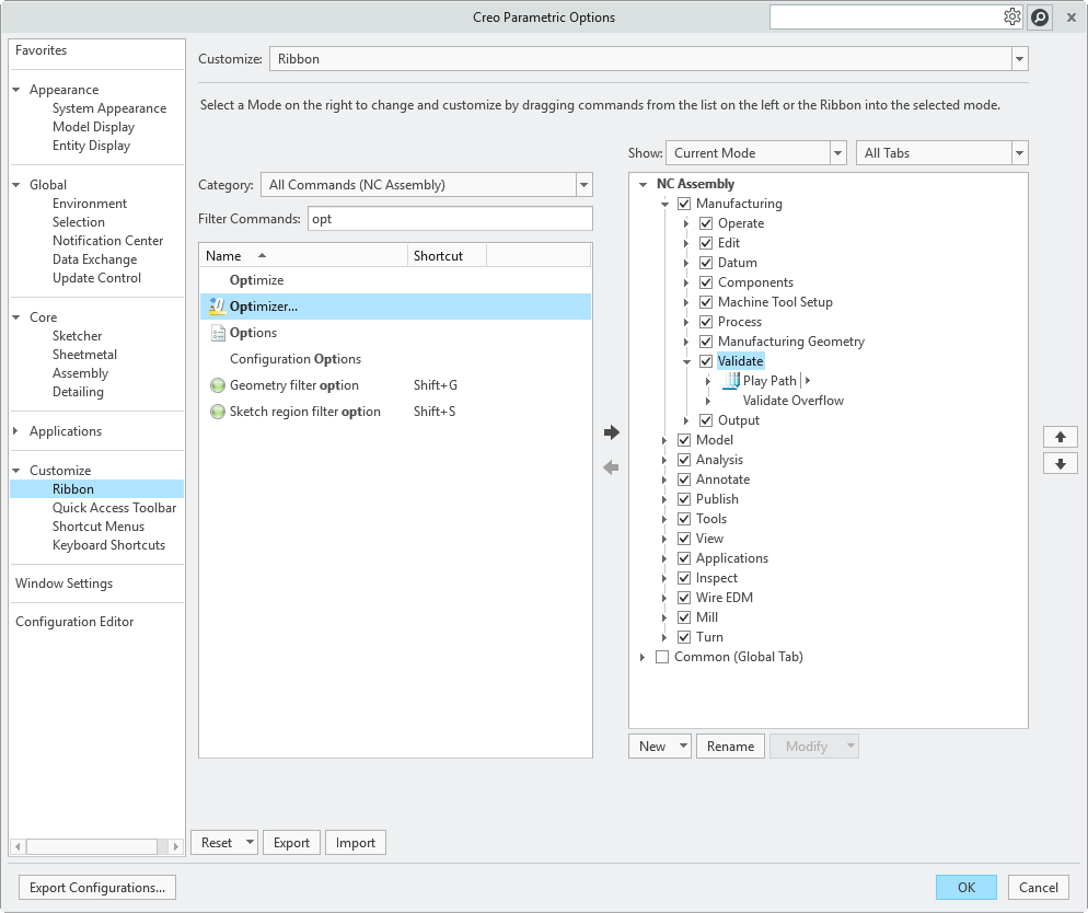
• Use arrow to add Optimizer to the desired location
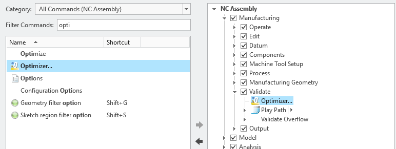
• Select Modify> Large Button
• Select Modify > Choose Button Image... and browse the Vericut32.gif
Reference: C:\Program Files\CGTech\Vericut x.x.x\windows64\proev\Creox.x\text\resource
• Select OK
Microsoft Redistributables
The interface may require the Install of Windows C++ run-time libraries (Microsoft Redistributables). The Microsoft Redistributable vc_redist.x64.exe Installer is also available for download at: https://learn.microsoft.com/en-us/cpp/windows/latest-supported-vc-redist?view=msvc-170
Usage
The Creo-to-Vericut Interface (PROEV) exports the Creo manufacturing data to Vericut, PROEV addresses the below Vericut setup requirements and then launches Vericut with the simulation ready to play.
The Vericut simulation requirements are:
-
Select a VMC (Vericut Machine Configuration)
-
Select and orient stock, fixture and design models
-
Select NC Programs & Subroutines
-
Define Cutting tools
-
Define Work Offsets Tables
Accessing the Creo-to-Vericut Interface
The PROEV dashboard is activated by clicking  Vericut from the Ribbon or from the Creo > Applications tab > Vericut

📝 NOTE: PROEV** requires an active NC Manufacturing file running in order to interface with Vericut.
User Interface & Operation
When you trigger PROEV from the toolbar, you should see a window similar to below:
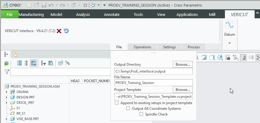
Click  to close the Vericut dashboard. Click
  to reset the Custom Data and close.
📝 NOTE: The Interface Checks Out a license while the Interface is generating Vericut files and then the Interface Checks In the license when the Interface is done generating Vericut files
File page:
PROEV will generate several files to pass Creo information to Vericut. For verification or simulation of a Creo manufacturing assembly, the following can be created;
• Vericut template file (*.VcTmp)
• Vericut Tool libraries (*.tls)
• Vericut Operation file (*.ops)
• Model files (*.stl and *.ply)
The Output Directory specifies the directory where you want the Vericut files to be written (.VcTemp, .tls, .ops, .ply, .stl). Type the Output Directory, or use the "Browse" button to display a file selection window to select the path.
The File Name specifies the "base" name for all Vericut files that will be created.
The files generated by PROEV are intended to be "add-ons" for existing Vericut projects that contain much more detail than is present in a Creo manufacturing assembly. For example, you may have a machine and control fully specified in a project file, and simply wish to place the Creo manufacturing assembly stock and fixtures on this machine before verifying the new NC programs. In this field you can specify the Project Template file. Type the Project Template, or use the "Browse" button to display a file selection window to select the Vericut project template.
📝 NOTE: The machine file, specified in the Project Template file, is used to extract all components and subsystems on the machine. The machine file is opened as it is defined in the template file. If it is not found, then the machine file is searched for in the same directory as the template file. If it does not exist in the same directory as the template file, then the machine file is searched for in the directories specified by the CGTECH_LIBRARY environment variable.
If you wish to append the part operations from a Creo manufacturing assembly to the setups that are already defined in your project template, you can click on the Append to existing setups in project template check-box under the template field. Otherwise, and more typically, the imported part operations will be the only setups in the generated project. If you wish to transfer all GibbsCAM part coordinate systems to Vericut, then you can click on the Output All Coordinate Systems check-box.
Spindle Check, In Creo it is no possible to know on witch spindle a Fixture, Stock and Design are mounted for an operation. You only know which Csys is associated at each spindle. When Spindle Check check-box is toggled on (checked), a Head/Subsystem assignment check is performed allowing the user to trigger the spindle axes recognition logic.
Operations Page:
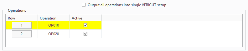
The Operations Table displays all operations in the Pro/ENGINEER manufacturing file. The currently highlighted operation is the operation in which all operation dependent settings will apply. To select an operation, press the button in the column labeled “row”. Only one operation can be selected at a time. An operation can be active or inactive by toggling on/off the check box in the column labeled “Active’. Only active Operations will be exported to Vericut.
Output all operations into a single Vericut setup: When toggled"on" (checked), PROEV will combine all the Creo operations into a single Vericut setup.
📝 NOTE: From the operations page, all operation dependent settings can be specified.
Setup Template Tab:
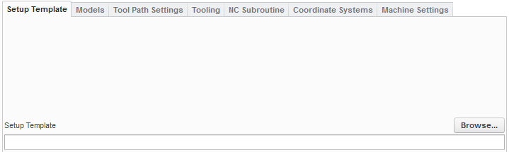
If all part operations in the Creo manufacturing assembly use the same machine, and that machine is defined in the project template file, then the setup template field can be left blank. If there are several machines involved, you will need to have a Vericut project file for each one, and will specify which file each setup should use in this field.
Models Tab:

The attach components are read from the machine file that is specified in the project template (or from the machine file specified in the setup template if defined) and presented in a pull down list called Attach Component. For each attach component, a set of models can be specified. Also for each attach component an Attach CSYS, Stock CSYS, fixture name, stock name, design name, stock cross section and design cross section can be specified. All attach components are active by default. The user can prohibit an attach component from being processed by unchecking the Active check box.
Attach CSYS is the Creo coordinate system that is associated with the Vericut Attach Component.
📝 NOTE: in Pro/E the ATTACH10 coordinate system is positioned to represent the location of the Vericut Attach component.
If Stock CSYS is specified, then the relationship between the Attach CSYS and the Stock CSYS is used for transitioning between Vericut setups, else the relationship between the current Attach CSYS and the Attach CSYS from the first operation is used.
📝 NOTE: Example of Pro/E – PROEV – Vericut process to transition the Cut Stock between setups.
Stock Tab:
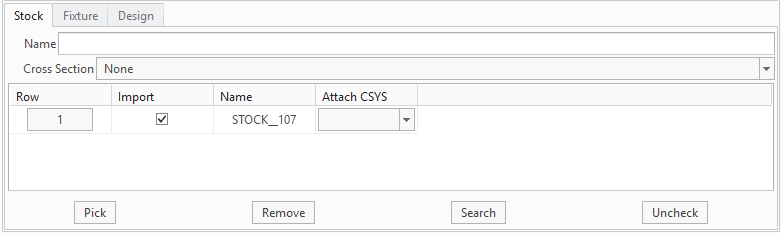
For each attach component, a set of stock models can be specified. Also for each attach component, a stock name, and stock cross section can be specified. The Pick button can be used to graphically pick multiple models/assemblies using the mouse. The Remove button can be used to remove models from the list. The Search button can be used to populate the list.
If the “Attach CSYS” is set to a spindle axes, then the search button will only populate the table with the models associated with the specified spindle axes. If the “Attach CSYS” is not set to a spindle axes, then the search button will populate the table with all models. The Import column allows the user to prevent models from being transferred. The Uncheck button can be used to toggle off all Import toggles. If the Attach CSYS at the model level is not blank, then it overrides the Attach CSYS at the Attachment level.
📝 NOTE: Cross sections must be created at the part level and not at the assembly level. Load part, create cross section, save part, and then load manufacturing assembly.
Fixture Tab:
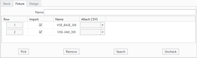
For each attach component, a set of fixture models can be specified. Also, for each attach component, a fixture name can be specified. The Pick button can be used to graphically pick multiple models/assemblies using the mouse. The Remove button can be used to remove models from the list. The Search button can be used to populate the list.
If the “Attach CSYS” is set to a spindle axes, then the search button will only populate the table with the models associated with the specified spindle axes. If the “Attach CSYS” is not set to a spindle axes, then the search button will populate the table with all models. The Import column allows the user to prevent models from being transferred. The Uncheck button can be used to toggle off all Import toggles. If the Attach CSYS at the model level is not blank, then it overrides the Attach CSYS at the Attachment level.
Design Tab:
Vericut:
Optimizer:
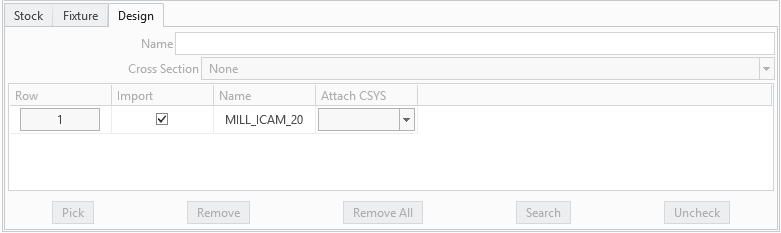
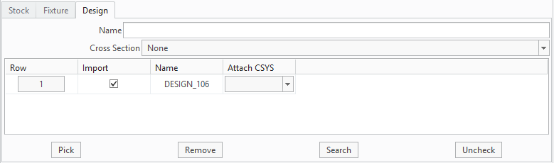
For each attach component, a set of design models can be specified. Also for each attach component, a design name, and design cross section can be specified. The Pick button can be used to graphically pick multiple models/assemblies using the mouse. The Remove button can be used to remove models from the list. The Search button can be used to populate the list.
If the “Attach CSYS” is set to a spindle axes, then the search button will only populate the table with the models associated with the specified spindle axes. If the “Attach CSYS” is not set to a spindle axes, then the search button will populate the table with all models. The Import column allows the user to prevent models from being transferred. The Uncheck button can be used to toggle off all Import toggles. If the Attach CSYS at the model level is not blank, then it overrides the Attach CSYS at the Attachment level.
📝 NOTE: Cross sections must be created at the part level and not at the assembly level. Load part, create cross section, save part, and then load manufacturing assembly.
Tool Path Settings Tab:
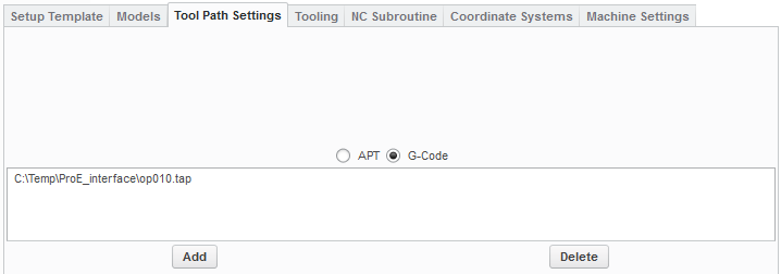
Specify whether the NC programs to be passed to Vericut are APT or G-Code. Use the “Add” button to browse for and add a tool path to the list. Use the “Delete” button to delete a tool path from the list. It is important to ensure that the list is in the order of cutting.
💡 Tip: Add the wild card filter (*) to the preference file (C:\Users\username\proev_creo6_user.prefs) filters... to make it easier to find files
ProevTpFilter,,.ncl,.tap,.mcd,.mpf,.ncl;.tap;.mcd;*.mpf
ProevSubFilter,,.sub
Tooling Tab:
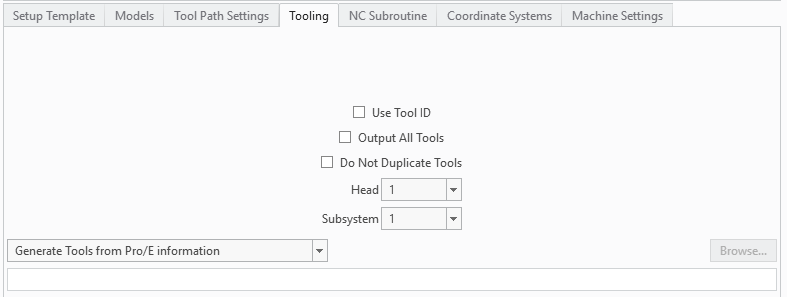
If the Use Tool ID check box is toggled on (checked), then the tool ID is used directly, else the tool list is used. Select which Head from the choice list. Select which Subsystem to use for the Head from the choice list.
The Output All Tools option is used to output all tools that are loaded into the CREO virtual machine.
If the Do Not Duplicate Tools check box is toggled on, then tools referenced by multiple NC Sequences will only be output once in the tool library file. Default behavior is that a tool will be output to the tool library file for each instance it is referenced by an NC Sequence.
Select which subsystem to use for head 1 from the Head 1 Subsystem ID choice list.
Select which subsystem to use for head 2 from the Head 2 Subsystem ID choice list.
Select one of the following options from the pull-down list:
• Generate Tools from Creo information — Choose this option to have Creo create a tool library using the tool data in Creo.
• Use Selected Tool Library — Choose this option to specify a specific tool library to use. Enter the \path\filename of the tool library file in the text field or use the Browse button to display a file selection window and use it to specify the \path\filename of the tool library file.
• Use Tools from the Setup Template — Choose this option to use the tool library file stored in the Setup Template instead of one created by PROEV.
• Merge Tools into Setup Template Tool Library — Choose this option to merge the tool library created by PROEV, with the tool library file stored in the Setup Template, and use the "merged" tool library rather than one created by PROEV.
If Use Selected Tool Library is selected, then type the tool library name in the text field or use the "Browse" button to display a file selection window to select the tool library file
PROEV supports both parametric and 3D holders are supported. In order for the 3D holders to be recognized by Pro/E, the working directory must be set to the directory in which the 3D holders reside.
NC Subroutine Tab:
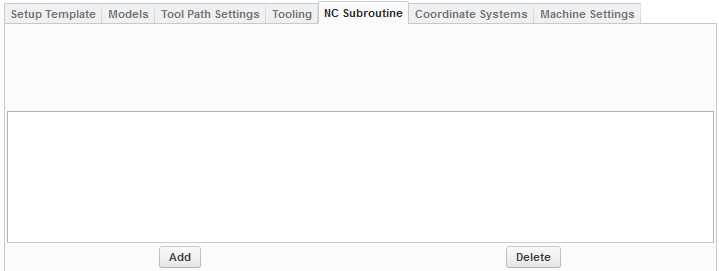
If you have G-Code programs that reference subroutines, you can use the “Add” button to browse for and add subroutine files to the list. Use the “Delete” button to delete subroutine files from the list.
Coordinate Systems Tab:
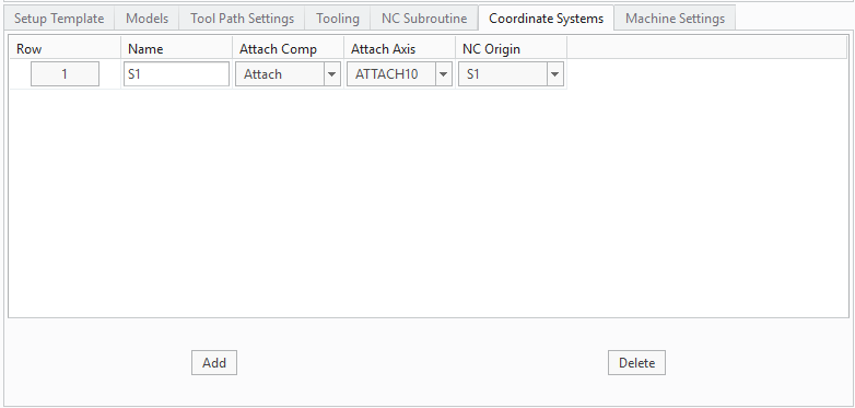
The Coordinate Systems list allows for the definition of a coordinate system that defines the relationship between an Attach Axis System and the NC Program Origin. Use the Add button to create a new coordinate system. A default coordinate system Name is assigned when created and can be changed and must be unique. The Attach Component is the Vericut component in which the coordinate system will be attached to. The Attach Axis System and the NC Program Origin are Creo Axis Systems. To select a coordinate system, press the button in the column labeled “row”. To unselect a coordinate system, press the button in the column labeled “row”. Multiple coordinate systems can be selected at a time. Use the Delete button to delete all selected coordinate systems.
Machine Settings Tab:
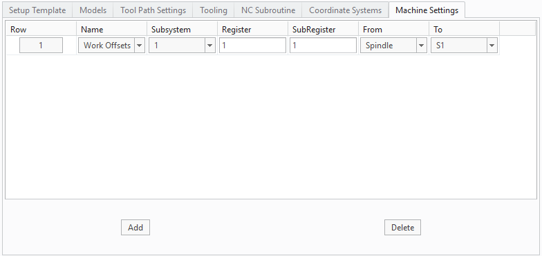
The Machine Settings list allows for the definition of work offsets which defines the relationship between the ‘From’ Component and the ‘To’ CSYS. Use the Add button to create a new work offset record. Table name can be Program Zero, Work Offsets, or Base Work Offset. Set the appropriate Subsystem ID, Register Number and Subregister Number. The ‘From’ Component is a Vericut component. The ‘To’ CSYS is a coordinate system defined in the Coordinate Systems list. To select a work offset, press the button in the column labeled “row”. To unselect a work offset, press the button in the column labeled “row”. Multiple work offsets can be selected at a time. Use the Delete button to delete all selected work offsets.
Settings Page:
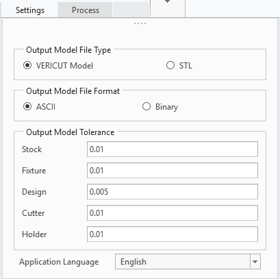
Use Output Model File Type to specify the type of model files that are created and passed to Vericut. Choose either Vericut Model (Vericut polygon file) or STL (Stereolithography model file).
Use Output Model File Format to specify the file format of the model files. Choose either ASCII or Binary. NOTE: "Binary" Vericut polygon files are platform specific.
Use the Output Model Tolerance to specify tolerance values for Stock, Fixture, and Design models. Use Application Language to set the default language for the program.
Use “Application Language” to specify native language.
Process Page:
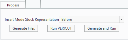
Set the Insert Mode Stock Representation choice list to Before, After, or Manual. If Before is selected, then the “Insert Here” will be moved right before the first Material Removal Feature. If After is selected, then the “Insert Here” will be moved right after the operation currently being processed. If Manual is selected, the “Insert Here” is not moved. This allows the user to manually move the insert.
When you have provided PROEV with all the information it needs, you can perform the transfer of data to, and triggering of, Vericut. Click on the "Generate files" button to create the appropriate files without triggering Vericut. Once you have all the files needed, you can fire up Vericut with the "Run Vericut" button. You can perform both of these steps at once with the "Generate and run" button.
See Operations File in the Getting Started section of Vericut Help for information on the Operations File (or Ops File).
Usage Variables
| No. | Environment Variable | Example |
|---|---|---|
| 1 | CGTECH_PROEV_TDP_ADJUST | 1 |
| 2 | CGTECH_PROEV_NEW_TLS | 1 |
CGTECH_PROEV_TDP_ADJUST set to activate logic which will ensure that the X and Z driven points are negative when the following three requirements are met...
- The environment variable CGTECH_PROEV_TDP_ADJUST is set to "1".
- The tool is a lathe tool.
- The tool is on head 2
CGTECH_PROEV_NEW_TLS
PROEV supports the new tooling API logic. To activate the new tooling API logic, set the following environment variable… set CGTECH_PROEV_NEW_TLS=1. If the above environment variable is not set, then the old tls logic is used.
Preferences
Preferences File
Also known as 'prefs' file, stores all user specified 'global' settings for interface operation. The settings stored are called 'global' because they are responsible for overall look & feel and operational behavior of the interface. They are not tied to any specific Pro/E project. By default, 'Preferences' file is generated at C:\Users\username\proev_Creoxx_user.prefs.
📝 NOTE: The 'prefs' file has support for environment variables in path names. The 'prefs' file only supports Vericut's environment variable convention ${...}, not windows batch file convention %...%.
Custom Data
The values that you set in any of the "PROEV" windows are saved as external data in the Creo manufacturing model. When you re-open the Creo manufacturing model, the "PROEV" settings are recalled as they were when you saved the file.
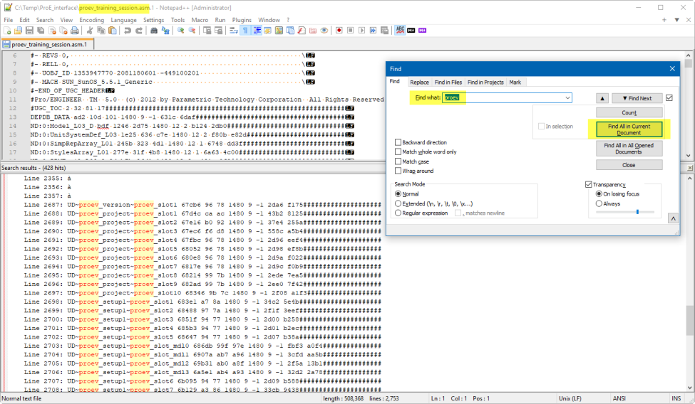
"Quick Start" training session
The Creo-to-Vericut Interface “Quick Start” training session is designed to quickly teach a Vericut user the “basics” of using the Creo Interface. The download includes: CAD/CAM files, Vericut files, and step-by-step training sessions in PDF format.
Download: https://vericut.com/products/vericut-interfaces
📝 NOTE: to run the Quick Start files, PTC CREO Elements Pro 5 or later is required.