Siemens NX-to-Vericut Interface (NXV)
Prerequisites
NXV is a licensed software program that provides a Siemens NX to Vericut data transfer.
Siemens NX Versions supported:
Siemens NX 2212 (or later)
CGTech Licensing:
NX Interface
Minimum Vericut Version required:
Vericut 8.0
Minimum Optimizer Version required:
1.1
Minimum Vericut License Version required:
9.4
Configuration
For the Siemens NX Interface, no user configuration is required. The interface installation files are located at C:\Program Files\CGTech\Vericut x.x.x\windows64\nx\version and can be accessed by C:\Program Files\CGTech\Vericut x.x.x\windows64\commands\nx(version).bat
Environment variables
To enable NX to find the necessary Vericut files, you also need to define three environment variables, CGTECH_INSTALL, CGTECH_PRODUCTS, and LSHOST. CGTECH_SINGLE_PLATFORM and CGTECH_LOCAL are optional.
| No. | Environment Variable | Example |
|---|---|---|
| 1 | CGTECH_INSTALL | C:\Program Files\CGTech\Vericut x.x.x |
| 2 | CGTECH_PRODUCTS | C:\Program Files\CGTech\Vericut x.x.x\windows64 |
| 3 | LSHOST | localhost |
| 4 | CGTECH_SINGLE_PLATFORM | YES |
| 5 | UGII_VENDOR_DIR | C:\Program Files\CGTech\Vericut x.x.x\windows64\nx\NXxx\french |
| 6 | CGTECH_NXV_LANGUAGE | french |
| 7 | CGTECH_VO_INSTALL | YES |
CGTECH_INSTALL is set to the Vericut installation folder. In the above table, x.x.x represents the Vericut release number. For a typical Vericut 9.7 installation this variable is set to C:\Program Files\CGTech\Vericut 9.7. Defining a value explicitly for the CGTECH_INSTALL environment variable is optional. It can be derived from the CGTECH_PRODUCTS environment variable value.
CGTECH_PRODUCTS is set to the folder for the specific operating system of the computer running Vericut: "windows64". In the above table, x.x.x represents the Vericut release number. For a typical Vericut 9.7 installation this variable is set to C:\Program Files\CGTech\Vericut 9.7\windows64.
LSHOST is set to the name of the license server computer.
CGTECH_SINGLE_PLATFORM=YES If you are using Vericut single Platform then an additional environment variable needs to be defined for the interface.
UGII_VENDOR_DIR is set to the NX Interface application folder.
CGTECH_NXV_LANGUAGE If you want the interface to use something other than US English, the variable can specify a file of localized text. If CGTECH_NXV_LANGUAGE is set to “abc” we take nxres.local from the “application\abc” folder. If CGTECH_NXV_LANGUAGE it is not set we look for the setting of UGII_LANG, and apply it the same way if found. Versions for French, German, Chinese, Czech, Portuguese and Japanese are supplied.
📝 NOTE:
For Portuguese use braz_portuguese
For Chinese use simpl_chinese
CGTECH_VO_INSTALL — if set to “yes” the Optimizer interface will start, otherwise it will be the Vericut interface. Note: One can also switch between the two using the radio buttons in the Options dialog.
Use the Microsoft Windows Control Panel System Properties Advanced tab Environment Variables feature to define these environment variables. See Microsoft Windows Help for more information.
To add an icon to the Toolbar
If you wish to have a Vericut icon ( ) on an NX 2306 toolbar…
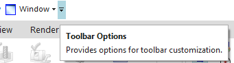
• Select Toolbar Options
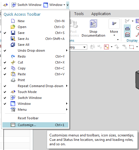
• Customize
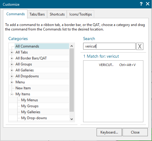
• Search for Vericut
• Drag and Drop command to desired location
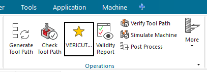
• Right click on icon > Change Icon > Icon Name
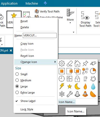
• Browse Button Image > C:\Program Files\CGTech\Vericut x.x.x\windows64\nx\NX_CR_2306\application\vericut_icon.bmp
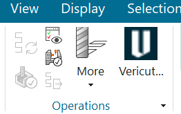
• Select Close
If you wish to add an Optimizer icon ( ) on an NX 2306 toolbar...
📝 NOTE: Step 1 should be set by the Installer, step 1 is for a manual installation
Modify cgtech.men file in the startup folder: it should point to cgtech_cam_VC.men for Vericut and to cgtech_cam_VO.men for Optimizer. You can copy cgtech.men_V to cgtech.men for Vericut, or copy cgtech.men_O to cgtech.men for Optimizer. The application folder contains both menu files: cgtech_cam_V.men and cgtech_cam_O.men.
Reference: C:\Program Files\CGTech\Vericut x.x.x\windows64\nx\NX_CR_xxxx\startup
Manually customize NX by adding the appropriate command and icon. Both icons are present in the application folder.
• Select Toolbar Options
• Customize
• Search for Optimizer
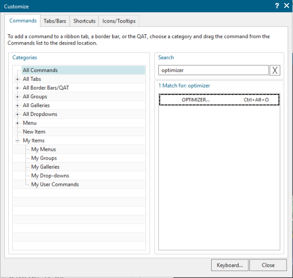
• Drag and Drop command to desired location
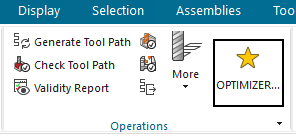
• Right click on icon > Change Icon > Icon Name
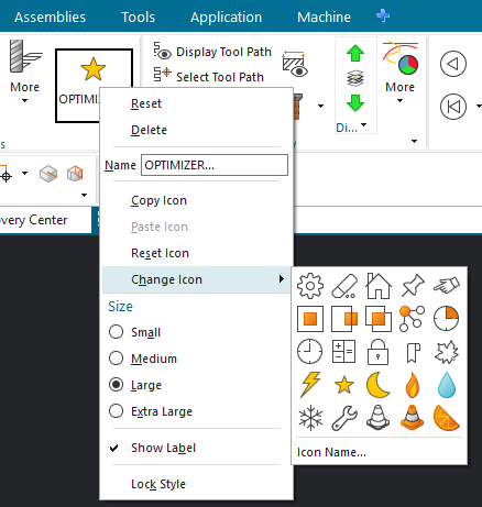
• Browse Button Image > C:\Program Files\CGTech\Vericut x.x.x\windows64\nx\NX_CR_2306\application\optimizer_icon.bmp
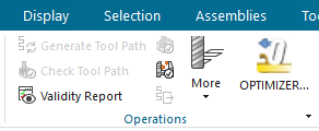
• Select Close
If you wish to have an icon () on an NX (NX 1980 - NX 2212) toolbar…
• Select Toolbar Options
• Customize
• Search for Vericut
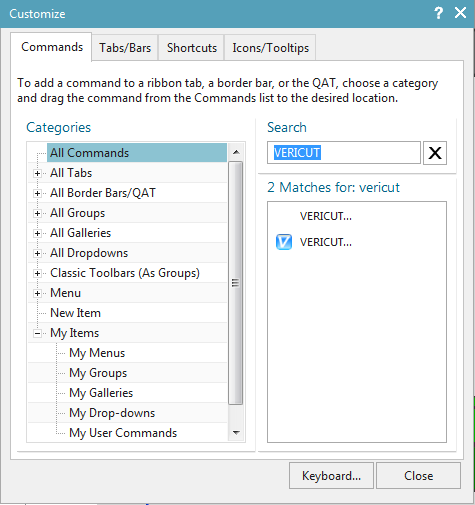
• Drag and Drop command to desired location
• Select Close
Microsoft Redistributables
The interface may require the Install of Windows C++ run-time libraries (Microsoft Redistributables). The Microsoft Redistributable vc_redist.x64.exe Installer is also available for download at: https://learn.microsoft.com/en-us/cpp/windows/latest-supported-vc-redist?view=msvc-170
Usage
The NX-to-Vericut Interface (NXV) exports the NX manufacturing data to Vericut, NXV addresses the below Vericut setup requirements and then launches Vericut with the simulation ready to play:
The Vericut simulation requirements are:
-
Select a VMC (Vericut Machine Configuration)
-
Select and orient stock, fixture and design models
-
Select NC Programs & Subroutines
-
Define Cutting tools
-
Define Work Offsets Tables
Accessing the NX-to-Vericut Interface
Vericut:
From the Toolbar select the Vericut ( ) icon or hold down the Ctrl key, hold down the Alt key, and click the V key ( Ctrl+Alt+V).
Optimizer:
From the Toolbar select the Optimizer icon  or hold down the Ctrl key, hold down the Alt key and click the O key (Ctrl + Alt + O).
📝 NOTE: NXV** requires an active NC Manufacturing file running in order to interface with Vericut (Ctrl + Alt + M)
User Interface & Operation
When you trigger NXV, you should see a window similar to this:
Vericut:
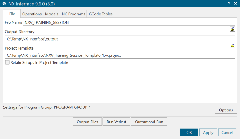
📝 NOTE: The Interface Checks Out a license when the Interface is opened and then the Interface Checks In the license when the Interface is closed.
File tab
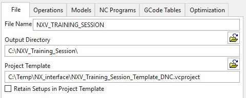
File Name: In the File Name text field, enter the "base" name for the Vericut files that will be created. By default, the base name of the NX .prt file is used.
Output Directory: NXV will generate several files to pass NX information to Vericut. All these files will be placed in a single folder. In the Output Directory text field, enter the /path/ to the directory where you want the Vericut files (.VcProject, .tls. CGTPart.stk, CGTStock.stk, etc.) output, or use the  button to display a file selection window and use it to specify the /path/. By default, the output directory is the "start in" directory of the NX session. Optionally you can set environment variable in the nx8.bat file. Example:
set CGTECH_NXV_OUTPUTDIR=C:\NXV_working_directory
Project Template: Enter the /path/filename of the "template" .VcProject file that you want loaded, in the text field, or use the button to display a file selection window and use it to specify the /path/filename. A Project Template is a previously defined Vericut .VcProject file that containing files and settings required for Vericut simulation. Optionally you can set environment variable in nx8.bat file. Example:
set CGTECH_NXV_PROJTEMPLATE=C:\NXV_working\NXV_Template.vcproject
Retain Setups in Project Template: Toggle “on” Retain Setups in Project Template to specify that you want to append the operations in the NX part file, to the setups that are already defined in your Project Template file so that setups from both files will be contained in the generated project file.
Operations tab
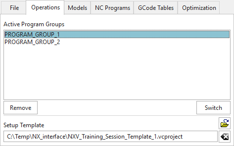
Active Program Groups: Select the name of the program group, from the Active Program Groups list, that you want to specify settings for. The "Settings For Program Group: program group name" will update to confirm your selection. Any settings that you make will apply to this program group until another program group is selected.
Remove/Restore and Switch Buttons: If there are some program groups that you do not wish to transfer to Vericut, select them on the Active Program Group(s) list and use the Remove button to move them to the Deleted Program Group(s) list. Click the Switch button to switch between displaying the Active Program Group(s) list and the Deleted Program Group(s) list. To restore previously deleted program groups to the Active Program Group(s) list, select them in the Deleted Program Group(s) list and click the Restore button.

Setup Template: If desired, enter the /path/filename of the Setup Template file that you want loaded, in the text field, or use the button to display a file selection window and use it to specify the /path/filename. A setup "template" is a previously defined Vericut.VcProject file that containing files and settings required for Vericut simulation. If this field is left blank the Project Template will be used.
Models tab
Vericut:
Optimizer:
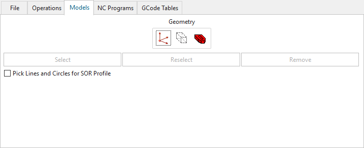
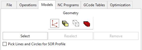
Geometry: By default, NXV automatically selects models associated with your NC operations. However, the following options can be used to select alternate geometry to use in the simulation:
📝 NOTE: In general, click the desired Geometry icon, then click Select and select the corresponding NX geometry. A window also display containing standard NX "Class Selection" tools to assist you in selecting geometry. Geometry items can be selected in any order, for example: stock-fixture-part, fixture-stock-part, etc. NX highlights selected geometry. Selections for each of the geometry options can be re-selected or cleared by selecting the corresponding geometry option, then clicking Reselect or Remove, respectively. Reselect and Remove are only available when geometry was previously selected.
 (Model Location): NXV will automatically position the Part, Stock and Fixture models from MCS origin of Program Group to Vericut ATTACH component. If you wish to output the Part, Stock and Fixture models relative to a different coordinate system, click
  , then select the coordinate system representing the orientation of the stock on the machine in Vericut. You must have previously set Output Model Relative To, on the Options window, to MCS/Coordinate System. All models will be output relative to the selected coordinate system.
 (Part): Click this option to select geometry to represent the design model, or theoretical finished part. Design models are used by Vericut's AUTO-DIFF function to detect gouges and excess material conditions. Geometry for use as a "Design Surface" model does not have to be solid or watertight.
 (Stock/Blank): Click this option to select geometry to represent the raw stock workpiece to be machined.
 (Fixture/Check): Click this option to select geometry to represent the fixture used to hold the stock for machining.
📝 NOTE: When selecting a coordinate system from the NX session, an MCS cannot be used.
NC Programs tab
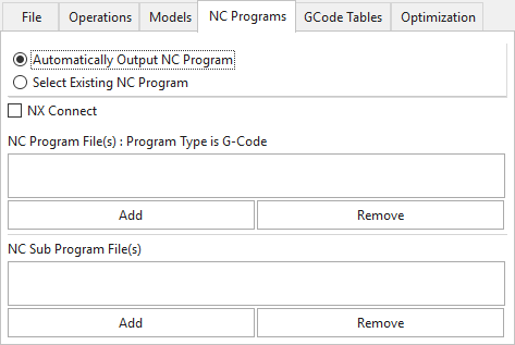
Automatically Output NC Program: To create a new NC program file to add to the NC Program File(s) list, select Automatically Output NC Program, and then select Add. NXV will automatically create a new .cls, or .ptp, file containing the operations related to the selected operations. If either the Program Group is selected, or no selection is made in the operation Navigator (ONT), NC code will be output for all operations. Otherwise, NC code will be output only for the operation(s) selected. NXV uses the settings in the Options window to determine whether a .cls file, or a .ptp file, is created for simulation.
Select Existing NC Program: To add an existing NC program file(s) to the NC Program Files list, toggle to Select Existing NC Program, and then select Add. NXV displays a standard file selection window enabling you to select existing files.
NC Program Files: Displays a list of NC Program files that will be passed to Vericut.
NC Sub Programs Files: Displays a list of NC Sub Program files that will be passed to Vericut. NC Sub Programs cannot be automatically created, they have to be selected.
Add — Use to add NC program/sub files to the NC Program/Sub Program File(s) list. When Select Existing NC Program is selected, NXV displays a standard file selection window enabling you to select existing files. When Automatically Output NC Program/Sub Program is selected, the configured NC code is output and added to the list.
Remove — Use to remove the highlighted NC program file(s) from the NC Program File(s) list.
NX Connect:
The NX Connect option of NXV will create a connection between Vericut and NX.
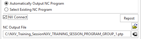
With this connection set, if the user selects an error from the Vericut Logger, the corresponding NX CAM Machining Operation will be highlighted in NX. With this option the user can easily identify an NX CAM Machining Operation responsible for that error.
Prerequisites:
• NX11 or higher
• VERICUT8.1 or higher
• NX postprocessor
📝 NOTES:
• NX and Vericut will run simultaneously. Vericut must be launched from NXV
• The NX Connect option is only available when the Automatically Output NC Program is checked.
• Machine Type, When Output and Run is selected NVX will generate a NC program with the postprocessor set
• If the NX CAM Machining Operation is updated, the user can select Repost to output an updated NC program and continue use the current connection with NX. No need to close Vericut OR NX.
GCode Tables tab
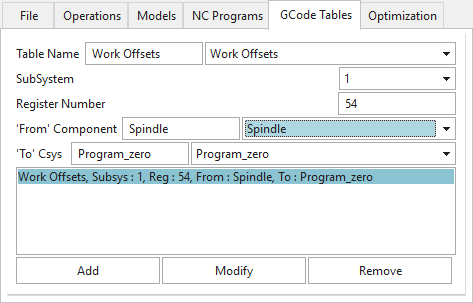
📝 NOTE: Data for the tables’ selection lists is taken from the machine specified in the Setup Template.
Table Name: Enter the G-Code table name or select it from the Table List pull-down list.
SubsystemID: Select the Subsystem from list.
Table List: The Table List pull-down list contains the following Vericut GCode tables: Work Offsets, Program Zero, and Base Work Offset.
The Work Offsets table is used to store the work coordinate system offset (fixture offset) values.
The Program Zero table is used to specify the programmed zero location of a GCode NC program file.
The Base Work Offset table is used to specify the location from which work offsets are based.
Register Number: If Work Offsets was selected as the Table Name, enter the work offset register, for example 54, 55, 56, etc.
'From' Component: Enter the name of the component that represents the "from" point for determining the program zero offset or select it from the 'From' List pull-down list. Vericut will use the origin of the specified component. The default "From Component" is "tool".
'To' Csys: Enter the name of a CSYS to represent the "to" point for determining the program zero offset in the text field or select the CSYS name from the 'To' List pull-down list. Vericut will use the origin of the specified CSYS. The default "To Csys" is a CSYS named "Program_Zero" which is derived from the MCS coordinate system.
The currently configured GCode Tables are displayed in the list below. The following buttons are used to manage the list of tables:
Add: Add the current GCode table to the list.
Modify: Modify the fields of the selected table by the current settings.
Remove: Delete the selected table(s) from the list.
Optimization tab
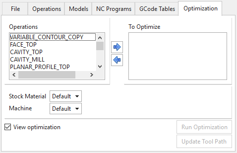
Operations: List of current used NX toolpaths in the session
To Optimize: List of current toolpaths to be optimized after Vericut optimization
 moves NX Toolpath from Operations list to To optimize list
 moves NX toolpath from To optimize list to Operation list
Stock Material: Specifies the stock material being cut. The material name is changed via clicking the arrow and selecting from a list of available materials. List comes from Vericut template + selected Tool manager.
Machine: Specifies the NC machine being used to cut the workpiece. This feature functions similar to Stock Material described above.
📝 NOTE: For optimization to occur, the Stock Material and Machine names must match those of the desired Stock Material records in the Tool Library file.
View optimization: Toggle on (checked) to run Optimization in batch mode. Vericut will open at the end of optimization for monitoring.
Run Optimization: NXV creates a Vericut project ready to optimize state with CLS file program file type for all setups.
Update Tool Path: Updates selected NX tool path with optimized feed rate and add more cuts if needed after optimization.
📝 NOTE: A series a time and date check are performed to ensure synchronization between Vericut and NX data.
Settings for Program Group: “program group name" will update to confirm your selection. Any settings that you make will apply to this program group until another program group is selected.

Options button

Models tab
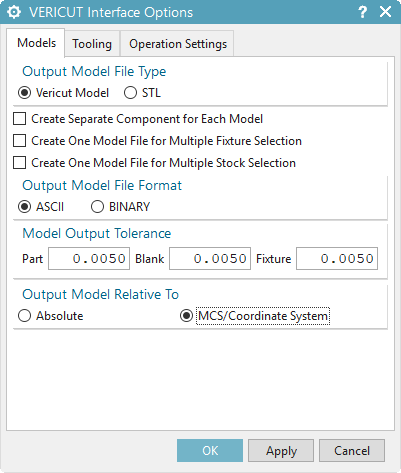
Output Model File Type: Use to specify the type of model files that are being passed to Vericut. Choose either Vericut Model (Vericut polygon file) or STL (Stereolithography model file).
Create Separate Component for Each Model: When toggled "on" (checked), NXV will create a component for each stock/fixture/design model. All the components will be on the same level under the Attach component, disregarding the tree structure in the setup template.
Create One Model File for Multiple Fixture Selection: When toggled “on” (checked), NXV will transfer multiple NX fixture models to Vericut as a single model file.
Create One Model File for Multiple Stock Selection: When toggled “on” (checked), NXV will transfer multiple NX stock model to Vericut as a single model file.
Output Model File Format: Use to specify the file format of the model files. Choose either ASCII or Binary. The "Binary" Vericut polygon files are platform specific.
Model Output Tolerance: Use to specify tolerance values for Part, Blank and Fixture models.
Output Model Relative To: Model files are output relative to a specific coordinate system. Use to specify whether model files will be output to the Absolute or MCS/Coordinate System.
Absolute: The Absolute choice is typically used for CLSF files because the CL file MSYS record takes care of tool point location transformation. If Absolute is selected, the following is output in the setup file for this program group:
• Models are output relative to absolute.
• Vericut Process Matrix is turned-on.
• A Vericut Csys is created for each MCS in each Program Group, attached to the stock component.
MCS/Coordinate System: The MCS/Coordinate System choice outputs the models relative to the MCS of the first operation in the program group, or relative to the selected coordinate system (new), if one exists. This choice is typically used for G-Code processing since there is no MSYS equivalent in the G-Code data. It is sometimes used by CLSF users when they only have one setup, and want the models located relative to the MCS, rather than absolute. If MCS/Coordinate System is selected, the following is output in the setup file for this program group:
• Models are output relative to the selected Program Group's MCS, or …
• Models are output relative to the selected coordinate system.
• Vericut Process Matrix is turned-off
• A Vericut Csys is created for each MCS in each Program Group, attached to the stock component.
MCS/Coordinate System output is sometimes used for a single-position CLSF where the user wants the models in the same coordinates as the MCS.
Tooling tab
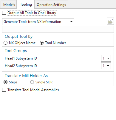
Output All Tools in One Library: Typically you would have NXV generate tool libraries (with the ".tls" extension) from the tool data in the NX part file for each setup. Alternatively, if you choose to create a single tool library for all setups, click on the Output All Tools in One Library check-box.
Select one of the following Tools options from the pull-down list:
Generate Tools from NX information: Choose this option to have NXV create a tool library using the tool data in NX.
Merge Tools into Setup Template Tool Library: Choose this option to merge the tool library created by NXV, with the tool library file stored in the Setup Template, and use the "merged" tool library rather than one created by NXV.
Use Tools from the Setup Template: Choose this option to use the tool library file stored in the Setup Template instead of one created by NXV.
Use Selected Tool Library: Choose this option to specify a specific tool library to use.
Enter the \path\filename of the tool library file in the text field or use the button to display a file selection window and use it to specify the /path/filename of the tool library file.
Output Tools By: Use to specify whether you want to output tools named with the NX Object Name (Default) or named with the NX Tool Number. Choose NX Object Name if you want the tool to have the NX object name as the Tool ID in Vericut. Choose Tool Number if you want the tool to have the NX tool number as the Tool ID in Vericut.
Tool Groups: Use to match Vericut subsystems with NX tool groups. This is needed to create the tool-change list. Used only when different tool groups are defined in NX, for turning or mill-turn machines.
Translate Mill Holder As: Enables you to specify whether to transfer an NX holder definition as individual SORs for each step or as a single SOR representing the complete holder:
Steps: Each Step in the NX holder definition is transferred as a separate SOR.
Single SOR: The NX holder definition is transferred as a single SOR.
Translate Tool Model Assemblies: When toggled “on” (checked), the NXV interface automatically creates a Step file for each referenced tool assembly; which can be processed by the CAD Import dialog in the Vericut Tool Manager. When toggled "off" (not checked), 3D assembly components are translated as faceted solid models (using the settings in the Options window) and these models are output as the tool components. If a tool assembly component has the name "CUT" the corresponding Vericut tool component will be "Insert", otherwise it will be "Holder". This is designed to enable the NXV interface to identify the Vericut tool component type for each NX tool assembly solid component. When toggled “off” (unchecked), NXV uses an NX SOR-like representation of the tool assembly as the tool component.
Operation Settings tab
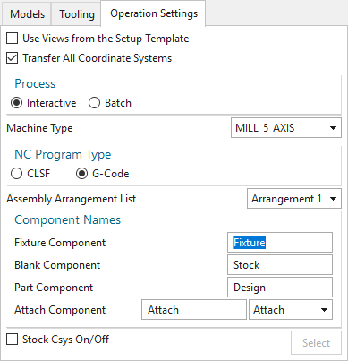
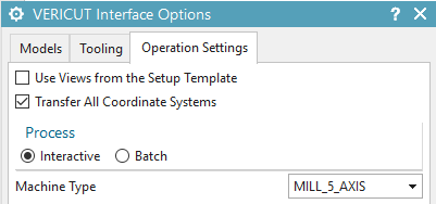
Use Views from the Setup Template: When toggled "on"(checked), Vericut will use the views stored in the Setup Template rather than the views created by NXV.
Transfer All Coordinate Systems: When toggled "on" (checked), NXV transfers all NX coordinate systems to Vericut.
Process: Controls the processing mode in which Vericut is run.
Interactive: Opens the Vericut window for access to all Vericut functions and capabilities. When the Vericut window opens, all of the required Vericut files are loaded and ready for processing. The stock is displayed in its unprocessed state and you need to press the "Play to End" icon in Vericut to start the verification process.
Batch: Runs Vericut unattended in the background. When the Vericut window opens, the toolpath verification process is complete and the part is displayed in its processed state.
📝 NOTE: In either case, both application windows (Vericut and NX) are available to work in at the same time.
Machine Type: Enables you to select the machine type that NXV is to use for creating G-Code files from the NX internal toolpath files.
NC Program Type: Use to specify the type of NC program files that are to be passed Vericut. Choose either CLSF or G-Code. This feature is used in conjunction with the Create for selected operations feature on the NXV Vericut window.
Assembly Arrangement List: The Assembly Arrangement List feature displays a list of all NX Assembly Arrangements available in the current part file. Select the desired Assembly Arrangement from the list. If no Assembly Arrangements exist in the current NX part file, the pull-down list displays "None".
Component Names:
Fixture Component: Enter the name of the Fixture component that is to be used for the current program group.
Stock Component: Enter the name of the Stock component that is to be used for the current program group.
Design Component: Enter the name of the Design component that is to be used for the current program group.
Attach Component: Enter the name of the Vericut attach component that is to be used for the current program group or select it from the list (containing all Attach components available in the current Setup Template).
Stock Csys On/Off: When the check box “Stock Csys On/Off” is checked the user can press “Select” to select the “Stock Csys” coordinate system. The currently selected “Stock Csys” coordinate system is highlighted, and the user can reselect it if he wishes. If the check box “Stock Csys On/Off” is checked, the currently selected “Stock Csys” coordinate system will be output with the name "STOCK” and used for cut stock transition.
If the check box “Stock Csys On/Off” is unchecked, no "STOCK” coordinate system will be output.
Output files
Vericut:

Optimizer:

Run Vericut: launches Vericut with the files created by Output Files.
Output Files: outputs all files, for all Program Groups, including the selected models, tool library files, updated project and setup files, and the "operations" file that assembles all of this information into a Vericut "project" file.
Output and Run: Use Output and Run to output the files needed by Vericut and then launch Vericut in the same step.
OK: Saves values that you set in the NXV windows as attributes the NX part file and closes the NXV Vericut window.
Apply: Saves values that you set in the NXV windows as attributes the NX part file and leaves the NXV Vericut window open to enable you to continue.
Cancel: Closes the NXV Vericut window without saving any of the settings in the NX part file.
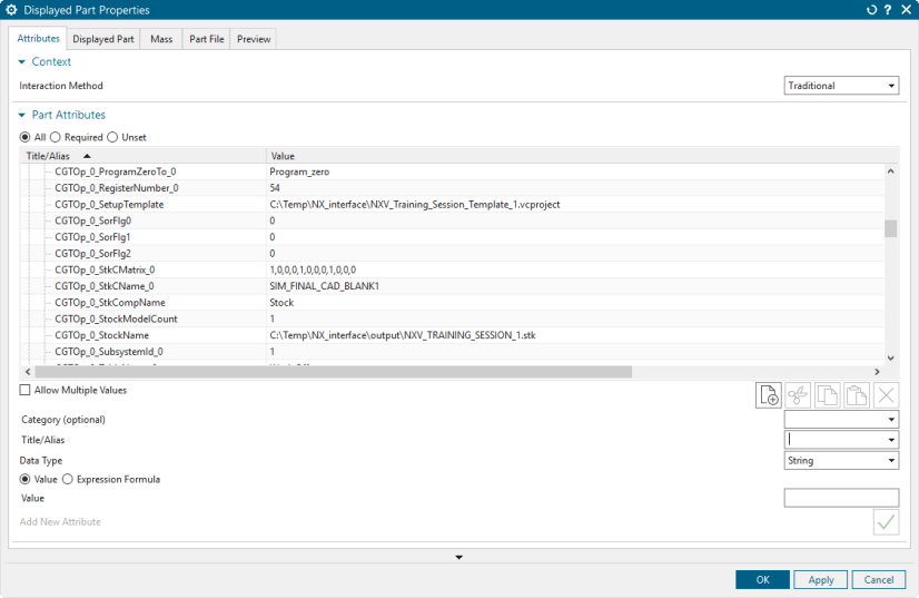
📝 NOTE: The values that you set in the NXV windows as attributes are saved in the NX part file so that when you save the part and later load it again, the values in the NXV dialog will be restored.
NX > File menu > Properties:
Usage Variables
The following optional environment variables are available for use with the Mastercam Interface.
| No. | Environment Variable | Example |
|---|---|---|
| 1 | CGTECH_NXV_OUTPUTDIR | C:\Temp\nxv\working\tmp |
| 2 | CGTECH_NXV_PREFSDIR | C:\Temp\nxv\working\tmp |
| 3 | CGTECH_NXV_PROJTEMPLATE | C:\Temp\nxv\working\NXV_Template.vcproject |
| 4 | UGII_CAM_LIBRARY_TOOL_GRAPHICS_PATH | C:\Temp\nxv\working\tmp |
| 5 | LREF_TOOL_DEBUG | 1 |
| 6 | CGTECH_NXV_DRIVEN_POINT_Z_OFFSET | 1 |
| 7 | CGTECH_NXV_LATHE_TOOL_X_MINUS | 1 |
| 8 | CGTECH_NXV_MILL_FORCE_CUTCOM_RECORD | 1 |
CGTECH_NXV_OUTPUTDIR set if the user wishes to set the NXV Output Directory.
CGTECH_NXV_PREFSDIR set if the user wishes to specify the location of the NXV preferences file. Default is %HOMEDRIVE%%HOMEPATH%.
CGTECH_NXV_PROJTEMPLATE set if the user wished to set the NXV Project Template.
UGII_CAM_LIBRARY_TOOL_GRAPHICS_PATH set if the user wishes to set directory for 3D tool models.
LREF_TOOL_DEBUG set if the user wishes to display the NX information window.
CGTECH_NXV_DRIVEN_POINT_Z_OFFSET set if the user wishes to alternate between two different orientations of referenced lathe tools
CGTECH_NXV_LATHE_TOOL_X_MINUS to alternate between two different orientations of referenced lathe tools set CGTECH_NXV_LATHE_TOOL_X_MINUS equal to 1
CGTECH_NXV_MILL_FORCE_CUTCOM_RECORD to force output of Cuter Compensation records for milling tools
Preferences
Preferences File
Also known as ‘prefs’ file, stores all user specified ‘global’ settings for interface operation. The settings stored are called ‘global’ because they are responsible for overall look & feel and operational behavior of the interface. They are not tied to any specific NX project. By default, ‘Preferences’ file is generated at C:\Users\username\nxv_version_user.prefs.
"Quick Start" training session
The NX-to-Vericut Interface “Quick Start” training session is designed to quickly teach a Vericut user the “basics” of using the NX Interface. The download includes: CAD/CAM files, Vericut files, and step-by-step training sessions in PDF format.
Download: https://vericut.com/products/vericut-interfaces
📝 NOTE: to run the Quick Start files, Siemens NX 8 or later is required.