Profile Sketcher window
The Profile Sketcher provides an easy graphical means of describing a profile in 2-D drawing space. Profiles are sketched by connecting a series of lines and arc segments. You can select points, enter point/arc data into the Profile entity list, or pick then edit entity values in the list. You can also import the 2-D geometry from a DXF file. The profile displayed in the sketcher window is constantly updated regardless of how you supply profile entity data, making it easy to see what you've defined.
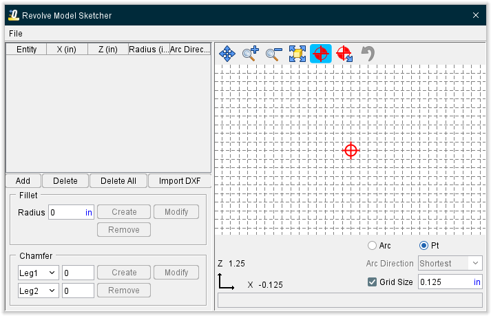
Revolve Profile" mode, where an "open" 2D profile is rotated about the Z-axis to create a solid model or cutter/holder or in "Sweep Profile" mode, where a "closed" 2-D profile is "swept" a specified distance along the Z-axis to create a solid model or a cutter insert/holder.
| Revolve | Sweep |
|---|---|
 |
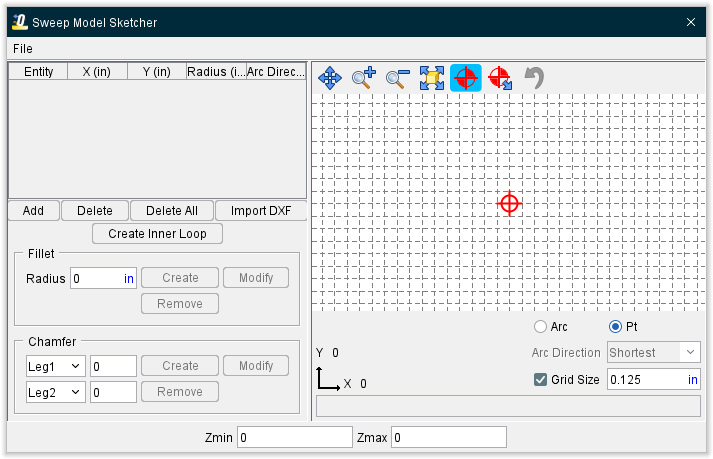 |
The Profile Sketcher is accessible from the Project Tree > Configure Component menu > Add Model > Revolve/Sweep, from the Project Tree > Configure Model menu: Model tab (Model File) > Sketcher and from Project Tree > Configure Model menu > Add Model > Revolve/Sweep to create profiles that can be rotated about an axis, or swept along an axis to create solid models.
The options available in the Profile sketcher will vary slightly depending on whether it was accessed from one of the Model menu windows or from Tool Manager. Most of the features are common regardless of where the window was accessed from and have identical functionality. Those features that are specific to a particular function are located at the bottom of the window are described in the Special Features section below.
File — Opens the file dropdown menu:
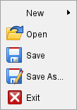
New — Hover this option to choose between opening a new Revolve or Sweep window.
Open — Use to load a previously created Revolve or Sweep.
Save — Stores the current profile sketcher.
Save As — Stores the current profile sketcher and allows you to rename it.
Exit — Closes the profile sketcher.
Entity list — Lists the point/arc entities that define the profile. The list is created by graphical selection, or by pressing Add to add entities to the list. Existing data can be edited directly in the Entity list.
Add — Adds a single entity to the Entity list. Once added, the entity type (Point or Arc) can be changed, or data values edited.
Delete — Deletes the highlighted entity from the Entity list.
Delete All — Deletes all entities in the Entity list.
Import DXF — Opens the DXF Geometry window enabling you import two dimensional tool geometry from files which comply with a de facto CAD system standard, the Data eXchange Format (DXF) to add (or modify) individual cutter (or holder) components in existing tool records.
Fillet
Radius — Use this text field to specify the radius of the fillet to be created or modified. Use with Create and Modify described below.
Create — Use to create a fillet at the selected point. Use Radius described above, to specify the size of the fillet.
Modify — Use to modify a fillet. Select the fillet in the Entity List and then set Radius to the new value. Finally, click on Modify to update the fillet.
Remove — Use to remove the highlighted fillet from the Entity List.
Chamfer
A chamfer can be defined at a corner between two line segments. To create a chamfer you need to select a corner point, and then define two length parameters: (leg1 + leg2), or a length and an angle parameter, e.g. (leg1 + angle2). See the picture on the following page.
If you specify two angle elements the chamfer will not be created, since two angles are not enough information to define a chamfer. A message will be displayed in the lower right corner of the Profile Sketcher window.
When a chamfer is defined it can be modified by selecting it and changing the type and/or the value of its defining parameters.
For example, if you defined a chamfer by leg1 = 1, angle1 = 30, you can now modify it by specifying angle1 = 35, leg2 = 1.2. While you are working on your sketch, each chamfer construction method will be remembered, and can be modified. However when you save the resulting profile all chamfers will be save just as line segments, the construction details forgotten.
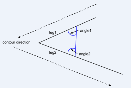
Entity 1 — Select one of the following entities (Leg1, Angle2, Angle1) from the pull-down list and then enter the value (distance or angle) for the selected entity in the in the text field next to the selected entity.
Entity 2 — Select one of the following entities (Leg2, Angle1, Angle2) from the pull-down list and then enter the value (distance or angle) for the selected entity in the in the text field next to the selected entity.
Create — Use to create a chamfer using the information supplied for Entity1 and Entity2 described above. Select Entity1 from the pull-down list and then enter the value in the text field.
Select Entity2 from the pull-down list and then enter the value in the text field. Finally, click on Create to create the chamfer.
Modify — Use to modify a chamfer. Select the chamfer in the Entity List and then set the new entity type and/or values. Finally, click on Modify to update the chamfer.
Remove — Use to remove the highlighted chamfer from the Entity List.
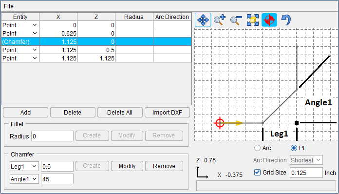
Example 1 – Create a 45 degree chamfer using a leg and an angle
- Set Entity 1 = Leg1 with a value of 0.5.
- Set Entity 2 = Angle 1 with a value of 45.
- In the Sketcher Entity List, select the intersection point of the 2 lines where you want the chamfer.
- Select Create to create the chamfer. See the diagram below.
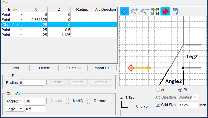
Example 2 – Create a 30 degree chamfer using a leg and an angle
- Set Entity 1 = Leg1 with a value of 1.
- Set Entity 2 = Angle1 with a value of 30.
- In the Sketcher Entity List, select the intersection point of the 2 lines where you want the chamfer.
- Select Create to create the chamfer. See the diagram below.
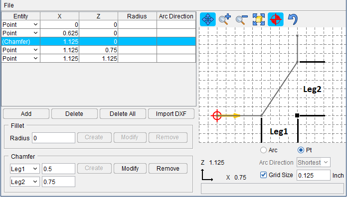
Example 3 – Create a chamfer using 2 legs
- Set Entity 1 = Leg1 with a value of 0.5.
- Set Entity 2 = Leg2 with a value of 0.75.
- In the Sketcher Entity List, select the intersection point of the 2 lines where you want the chamfer.
- Select Create to create the chamfer. See the diagram below.
↘️ Shortcut: Clicking with the right mouse button in the Sketcher window (Revolve Profile or Sweep Profile) displays the following shortcut menu:
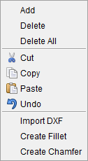
Most of these features provide the same functionality as those described above under Common Features.
The Create Inner Loop feature is only available in the Sweep Profile window and is described below in the Special Features section.
Sketcher window — Displays the current defined tool profile (blue line), based on the entity list. The profile in the window is constantly updated to reflect current list data. The following symbols may be seen in the sketcher window:
 Tool origin — The tool origin is assumed by Optimizer to be the control point, or driven point, on the tool. Typically, tool profiles are sketched relative to the tool origin to provide proper cutting by the tool. However, the tool origin can be relocated at any time via dragging the origin point. Tool origin display is controlled by the Origin
  feature on the sketcher Toolbar (see below).
 (blue dot) Entity point — This symbol indicates a point on the profile or an arc center point. You can change the profile shape by dragging entity points to different locations. The corresponding entity in the list is automatically updated.
 (green dot) Selected entity point — This symbol indicates the entity selected for editing. The corresponding entity in the list is also highlighted for editing.
📝 NOTE: Selecting a line segment in the Sketcher window selects both end points for editing. Drag the line segment to the desired location and both end points are automatically updated in the Sketcher window as well as in the Profile Entity List.
 (red dot) Target selection point — This symbol follows the mouse and is the target for graphical selection. Values displayed with the Sketcher axes below the sketcher window reflect the target selection point location.
Sketcher axes — Axes that depict the coordinate system in which the tool profile is being constructed. Values displayed with the axes reflect the target selection point location, relative to the tool origin.

 (Arrow) — The arrow on the profile indicates the direction.
Arc / Pt — Controls the profile entity type being defined via graphical selection.
Arc Direction — Controls the direction of an Arc being defined via graphical selection.
Grid Size — When selected, displays a grid in the sketcher window. When a grid is displayed, target and selected points snap to the nearest grid line intersection. Grid spacing is specified in the data field located right of the Grid Size label, and can be changed at any time. Clear the checkbox to remove the grid and select or drag points anywhere in the 2-D drawing space.
Sketcher Message area — Located below the sketcher window, this un-editable text field displays error and informational messages to assist you with defining tool profiles. If actions in the Tool Manager, and/or sketcher, window are not as expected, check the main window message area for additional relevant messages.
Sketcher Toolbar — The icons on this Toolbar zoom in/out, fit, and pan the tool profile in the sketcher window. See the table below for details. Sketcher icons:
↘️ Shortcut: The following keys provide instant access from the keyboard to dynamic viewing options (press and hold keys while dragging): Dynamic Zoom — <Ctrl>, Dynamic Pan — <Shift>.
| Icon: | Name: | Action: |
|---|---|---|
 |
Pan | Pan/translate- drag mouse in the direction pan |
 |
Zoom In | Zooms in approximately 20% each time it is clicked |
 |
Zoom Out | Zooms out approximately 20% each time it is clicked |
 |
Fit | Fits the tool in the sketcher window |
 |
Origin | When selected, displays the tool origin point |
 |
Origin Translate | When selected, enables you drag the origin to a new location |
 |
Undo | Select to "undo" the previous action(s). |
Special Features
The following features are only available in the Sweep Profile window:
Create Inner Loop — Use to create "inner loops" within the main profile used for creating "swept" solid models. The "inner loops" will result in open areas in the "swept" solid model. This feature is not available when the Sweep Profile window is accessed from Tool Manager.
Example:
The following Sweep Profile window shows a main profile with four different shaped "inner loops".
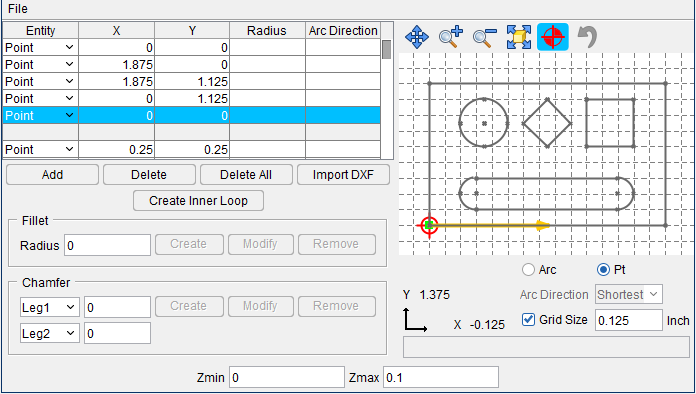
Zmin / Zmax — Used to specify the starting and ending location along the Z-axis when creating a "swept" solid model.
The following features are only available when the Sweep or Revolve Profile window is accessed from the Tool Manager. The specific features available will vary depending on the tool type (Mill, Turn, or Probe) and the tool component type (Revolved Cutter, Insert Cutter, or Holder) and the profile window type (Sweep or Revolve).
Color — Color that the tool component is to be displayed in.
Do Not Spin with Spindle — Toggle On (checked), or Off (not checked), to specify whether or not the holder component spins with the spindle. For example, a milling tool holder would spin with the spindle, while a turning tool holder would not.
Flute Length — Used to specify the length of the cutter having flutes or teeth that can remove material.
Spindle Direction — Use to specify spindle direction for a specific revolved cutter. Choose CW (clockwise) or CCW (counterclockwise).
Thickness — Used to specify the thickness of the insert or holder (sweep profile only).
Alternate — When toggled "on" (checked) this feature designates the cutter that is being created as an "alternate" or "secondary" cutter for a particular tool assembly. This feature enables you to switch between a "primary" and "alternate" cutter shape, in order to support tools such as back-boring tools.
The AlternateTool macro is used to specify whether to use the "primary" (Override Value = 0) cutter shape or to use the "alternate" (Override Value = 1) cutter shape.