Project Tree Right Mouse Button (RMB) Menus
Right-clicking on an item in the Project Tree will generate pop-up menus full of features you can click. This enables you to access relevant features more quickly than using the Menu ribbon. Each menu contains some common features that are shared with many right mouse button menus and some features that are specific to only that menu of that feature on the Project Tree.
Open group
These common features have to do with loading and saving files.
Open — Displays the Open Project file selection window enabling you to open an existing project file.
Save — Use to save an existing project file with the current Optimizer session settings.
Save As — Opens the Save Project As window, enabling you to save the current project file under a different name, or in a different location.
Cut/Copy/Paste group
These common features have to do with standard cutting, copying, and pasting of information.
Cut — Cuts the highlighted component branch from the Project Tree and puts it in the paste buffer.
Copy — Copies the highlighted component branch from the Project Tree to the paste buffer.
Paste — Uses the contents of the paste buffer to replace the highlighted component branch in the Project Tree.
Delete — Removes the highlighted component branch from the Project Tree.
Delete All — Removes all child branches from the Project Tree.
Rename — Use to rename the highlighted component branch.
Expand group
These common features control when subcomponents are displayed or hidden.
Expand All Children — Expands all sub-branches of your currently selected branch.
Expand Components — Expands all child branches of the selected (highlighted) component.
Collapse All Children — Collapses all sub-branches of your currently selected branch.
Project RMB
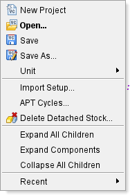
New Project — Displays the New Optimizer Project window enabling you to create a New Project file.
Unit — Use this option to toggle between Inch and Millimeter measurements.
Import Setup — Opens the Import Setup window, enabling you to copy a setup from either a pre-V6.0 user file, or from a V6.0 or later project file, and append it after the current setup.
APT Cycles — Opens the Cycles window enabling you to maintain cycle and modal definitions.
Delete Detached Stock — Removes selected stock from the project.
Recent — Displays a list of recently used files to open quickly.
All remaining options are described in the Common Features intro section at the top of this page.
Setup RMB
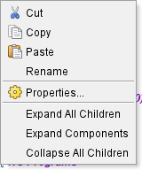
Properties — This opens the Properties window.
All remaining options are described in the Common Features intro section at the top of this page.
CNC Machine RMB
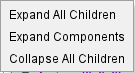
All options are described in the Common Features intro section at the top of this page.
Control RMB
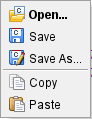
All options are described in the Common Features intro section at the top of this page.
Machine RMB
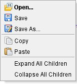
All options are described in the Common Features intro section at the top of this page.
Fixture RMB
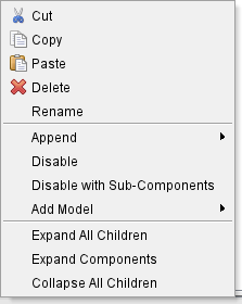
Append — Use this option to add a new stock to the Project Tree. Options are Fixture and Stock.
Disable — Use to make the selected model active or inactive in the machining process.
Disable with Sub-Components — Use to make the selected model and all of its sub-components active or inactive in the machining process.
Add Model — The Add Model pull-down list contains the model types that can be added to an Attach Component. Options are: Block, Cone, Cylinder, Model File, Create Revolve, and Create Sweep.
All remaining options are described in the Common Features intro section at the top of this page.
Stock RMB
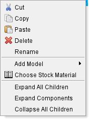
Add Model — The Add Model pull-down list contains the model types that can be added to an Attach Component. Select from the listed model types.
Choose Stock Material — Opens a Stock Material Catalog window enabling you to select a material from a preset list to use as a component.
All remaining options are described in the Common Features intro section at the top of this page.
Models RMB
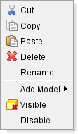
Add Model — The Add Model pull-down list contains the model types that can be added to an Attach Component. Select from the listed model types.
Visible — Use to make the highlighted Attach Component visible, or not visible, in the Optimzer graphics area. The Visible icon will indicate the visibility status of the model.  indicates "visible",
  indicates "not visible". Click on Visible to toggle between the two modes. In the Project Tree, any Attach Component in the "not visible" state will be displayed in gray instead if a color.
Disable — Use to make the selected model active or inactive in the machining process.
All remaining options are described in the Common Features intro section at the top of this page.
Coordinate Systems RMB
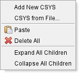
Add New CSYS — Generates a CSYS to edit in the Project Tree.
CSYS from File — Displays a file selection box enabling you to specify the CSYS file to be used.
All remaining options are described in the Common Features intro section at the top of this page.
CSYS RMB
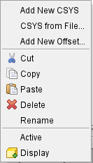
Add New CSYS — Generates a CSYS to edit in the Project Tree.
CSYS from File — Displays a file selection box enabling you to specify the CSYS file to be used.
Add New Offset — Generates a new G-Code Offset to edit in the Project Tree.
Active — Click on this option to make the selected CSYS the coordinate system that Optimizer will use in positioning stock.
Display — Use to make the highlighted CSYS visible, or not visible, in the Optimzer graphics area. The icon will indicate the visibility status of the model. indicates "displayed", indicates "not displayed". Click on Display to toggle between the two modes. Displayed CSYS will be visible the Graphics Area.
All remaining options are described in the Common Features intro section at the top of this page.
G-Code Offsets RMB

All remaining options are described in the Common Features intro section at the top of this page.
Tooling RMB
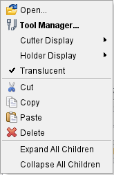
Tool Manager — Clicking this option opens the Tool Manager window.
Cutter Display — Use this pop-up menu to select how cutters are displayed in the Graphics Area. Options are: Invisible, Workpiece View, Machine View, and Both Views.
Holder Display — Use this pop-up menu to select how holders are displayed in the Graphics Area. Options are identical to Cutter Display options.
Translucent — Selected this option to make tools see through.
All remaining options are described in the Common Features intro section at the top of this page.
NC Programs RMB
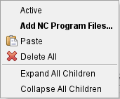
Active — When toggled “on” (checked), all NC program files in the NC Programs branch are designated “active”. When toggled “off”, all NC program files in the NC Programs branch are designated as “inactive”. Only NC program files designated as “active” are processed by Vericut. "Inactive" NC program files are indicated by red text in the Project Tree panel.
Add NC Program Files — Displays the NC Programs file selection window enabling you to add one, or more, NC programs to the setup.
All remaining options are described in the Common Features intro section at the top of this page.
NC Subroutines RMB
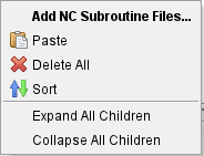
Add NC Subroutine Files — Displays the NC Programs file selection window enabling you to add one or more external subroutine files.
Sort — Reorders the NC Subroutine Files.
All remaining options are described in the Common Features intro section at the top of this page.