Mastercam-to-Vericut Interface (McamV)
Prerequisites
MCAMV is a licensed software program that provides a Mastercam to Vericut data transfer connection. The interface is a C-Hook that is designed to work with Mastercam.
Versions supported:
Mastercam (2024 or later)
CGTech Licensing:
Mastercam Interface
Minimum Vericut Version required:
Vericut 8.0
Minimum Optimizer Version required:
1.1
Minimum Vericut License Version required:
9.4
Configuration
To automatically install the Mastercam to Vericut interface (McamV), insert the Vericut installation folder of the downloaded Vericut installer. Next, run the mastercam_interface_install.exe and follow the on-screen instructions.
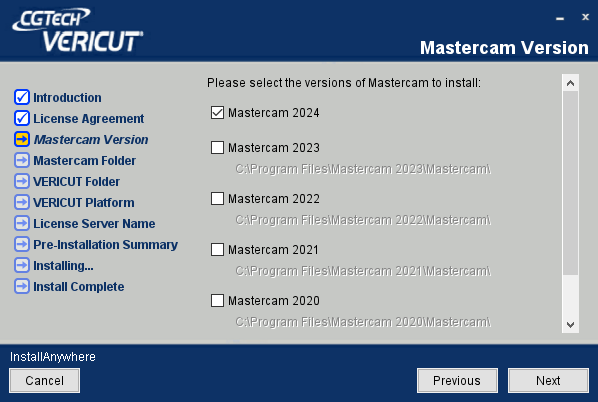
Installer: https://vericut.com/previous-vericut-release
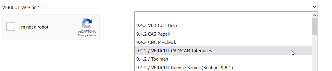
Manual installation
The following section describes how to install the Mastercam-to-Vericut Interface without using the installer. This Vericut C-Hook is for Mastercam xxxx. It is distributed as seven files located in the C:\Program Files\cgtech\Vericut x.x.x\windows64\mcamv\Xv directory of the Vericut installation. The x.x.x represents the Vericut release number.
Vericut.dll (the code)
VericutSupport.dll (supporting code)
VericutSupport1.dll (supporting code)
SetStock.dll (gets the parameters for a Lathe Stock from Mastercam source code)
Vericut.ft (used to map an Icon into the Mastercam menu interface)
Optimizer.ft (used to map an Optimizer Icon into the Mastercam ribbon)
mcRes.local (language translation)
Step 1
The four .dll files and the 2 .ft files should be placed in Mastercam's "chooks" folder.
Copy from C:\Program Files\CGTech\Vericut x.x.x\windows64\mcamv*version*
Copy to C:\Program Files\Mastercam version\chooks
Vericut.dll
VericutSupport.dll
VericutSupport1.dll
SetStock.dll
Vericut.ft
Optimizer.ft (used to map an Optimizer Icon into the Mastercam ribbon)
Step 2
The mcRes.local should be placed in the Mastercam installation folder.
Copy from C:\Program Files\CGTech\Vericut x.x.x\windows64\mcamv*version*
Copy to C:\Program Files\Mastercam version
📝 NOTE: Languages supported by McamV:
German
English
French
Portuguese
Chinese
Japanese
Environment variables
To enable Mastercam to find the necessary Vericut files, you also need to define three environment variables, CGTECH_INSTALL, CGTECH_PRODUCTS and LSHOST. CGTECH_SINGLE_PLATFORM is optional.
| No. | Environment Variable | Example |
|---|---|---|
| 1 | CGTECH_INSTALL | C:\Program Files\CGTech\Vericut x.x.x |
| 2 | CGTECH_PRODUCTS | C:\Program Files\CGTech\Vericut x.x.x\windows64 |
| 3 | LSHOST | localhost |
| 4 | CGTECH_SINGLE_PLATFORM | YES |
| 5 | CGTECH_VO_INSTALL | YES |
CGTECH_INSTALL is set to the Vericut installation folder. In the above table, x.x.x represents the Vericut release number. For a typical Vericut 9.7 installation this variable is set to C:\Program Files\CGTech\Vericut 9.7. Defining a value explicitly for the CGTECH_INSTALL environment variable is optional. It can be derived from the CGTECH_PRODUCTS environment variable value.
CGTECH_PRODUCTS is set to the folder for the specific operating system of the computer running Vericut: "windows64". In the above table, x.x.x represents the Vericut release number. For a typical Vericut 9.7 installation this variable is set to C:\Program Files\CGTech\Vericut 9.7\windows64.
LSHOST is set to the name of the license server computer.
CGTECH_SINGLE_PLATFORM=YES If you are using Vericut single Platform then an additional environment variable needs to be defined for the interface.
CGTECH_VO_INSTALL — if set to “yes” the Optimizer interface will start, otherwise it will be the Vericut interface. Note: One can also switch between the two using the radio buttons in the Options dialog.
Microsoft Redistributables
The interface may require the Install of Windows C++ run-time libraries (Microsoft Redistributables). The Microsoft Redistributable vc_redist.x64.exe Installer is also available for download at: https://learn.microsoft.com/en-us/cpp/windows/latest-supported-vc-redist?view=msvc-170
To add an icon to the Toolbar
If you wish to have an icon to the Mastercam toolbar…
• From the Mastercam Quick Access Toolbar, select More Commands
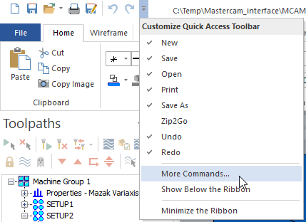
• Select Customize Ribbon
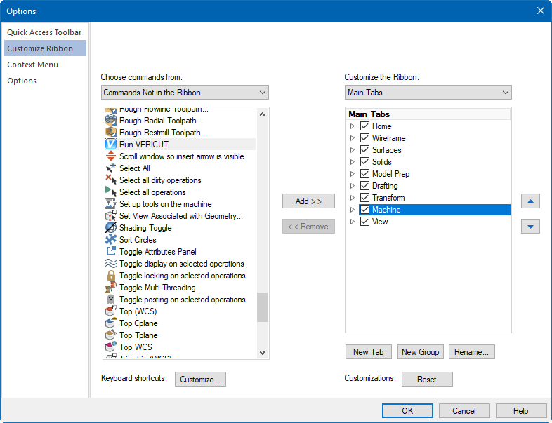
• Add a New Group to the Machine tab
• Rename to Vericut or Optimizer and
• Add the Run Vericut or Run Optimizer Icon
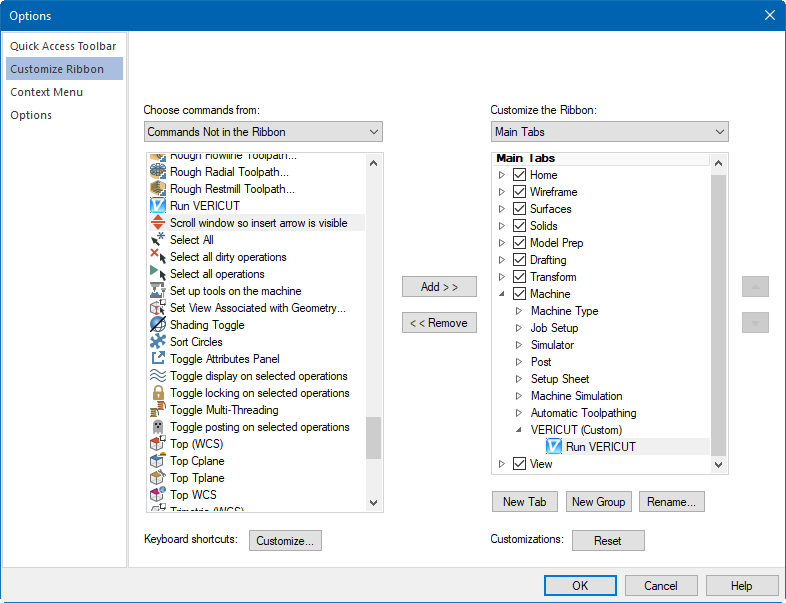
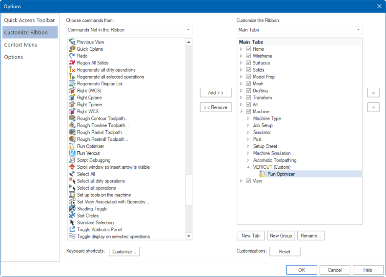
• Select OK
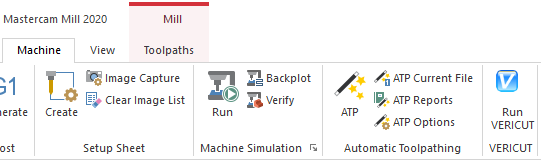
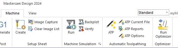
Usage
The Mastercam-to-Vericut Interface (MCAMV) exports the Mastercam manufacturing data to Vericut, MCAMV addresses the below Vericut setup requirements and then launches Vericut with the simulation ready to play:
The Vericut simulation requirements are:
-
Select a VMC (Vericut Machine Configuration)
-
Select and orient stock, fixture and design models
-
Select NC Programs & Subroutines
-
Define Cutting tools
-
Define Work Offsets Tables
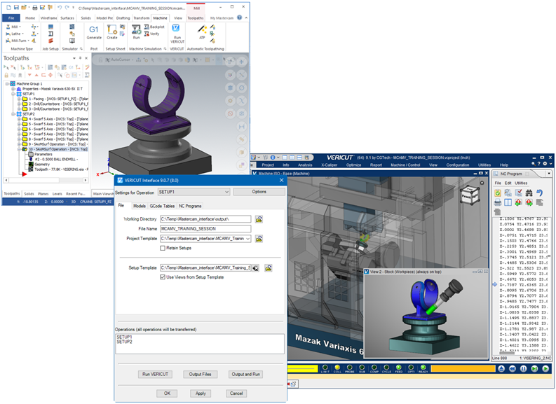
Accessing the Mastercam-to-Vericut Interface
From the Mastercam Toolbar select the Vericut ( ) or Optimizer (
 ) icon or hold down the Alt key and click the C key (referred to as Alt-C).
📝 NOTE: McamV** requires an active NC Manufacturing file running in order to interface with Vericut.
User Interface & Operation
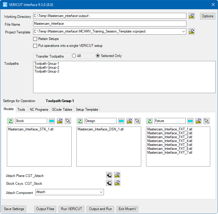
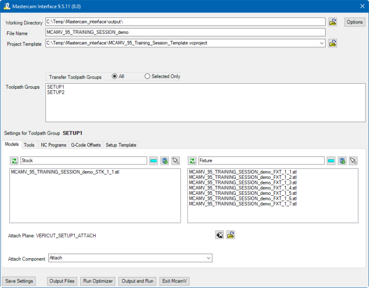
When you trigger McamV, you should see a window similar to this:
Vericut:
Optimizer:
📝 NOTE: The Interface Checks Out a license when the Interface is opened and then the Interface Checks In the license when the Interface is closed.
Options
The Options button opens the Options window.
Application Tab: Specify general McamV options.
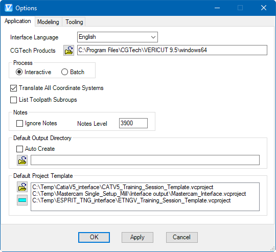
Interface Language: Allows you to change the current language of the interface. This change takes effect immediately.
CGTech Products: Allows you to change the directory used to launch Vericut from the interface. This directory is initialized by the CGTECH_PRODUCTS environment variable.
Process: Controls the processing mode in which Vericut is run.
Interactive: Opens the Vericut window for access to all Vericut functions and capabilities. When the Vericut window opens, all of the required Vericut files are loaded and ready for processing. The stock is displayed in its unprocessed state and you need to press the "Play to End" icon in Vericut to start the verification process.
Batch: Runs Vericut unattended in the background. When the Vericut window opens, the toolpath verification process is complete and the part is displayed in its processed state.
📝 NOTE: In either case, both application windows (Vericut and Mastercam) are available to work in at the same time.
Translate All Coordinate Systems: When toggled "on" (checked), McamV transfers all Mastercam coordinate systems to Vericut.
List Toolpath Subgroups: When toggled "on" (checked), McamV lists every toolpath group in the Toolpaths tree structure as separate entry in the Toolpath Groups list. The default state (when not checked), is when only top-level toolpath groups are listed.
Notes
Ignore Notes: When toggled "on" (checked), McamV will not read the interface data stored with the Mastercam part. This setting is supported by a ‘prefs’ file, and will take effect the next time McamV is launched.
Notes Level — Allows you to select the Mastercam level where McamV data is stored (as Mastercam note entities). The default level is 3987, however it may be unsuitable for some reason. Generally the ‘Notes’ level is supposed to contain only the McamV data.
Default Output Directory
Auto Create: When toggled "on" (checked) the Output Directory will be “part_directory\output”, it will be created or used if already exists. (Here “part_directory” is the current Mastercam part location). You can also select a different Output Directory in the text box below.
Default Project Template
This is the list of Vericut project files that is used to form a selection of project templates. You can add to the list using the  (Browse) icon, or remove items using the
  (Remove) button.
Modeling tab
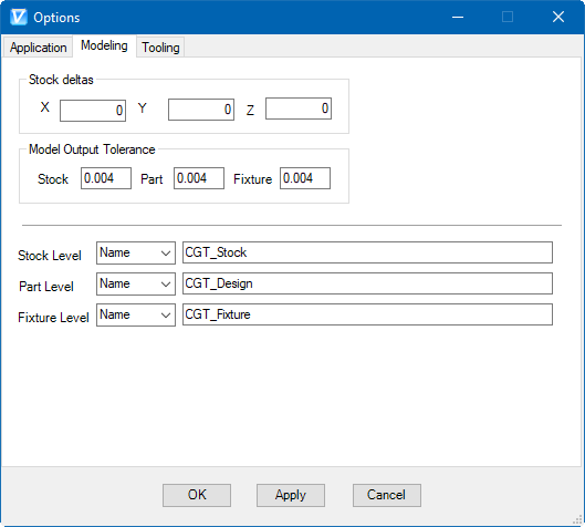
Specify options for model output.
Vericut:
Optimizer:
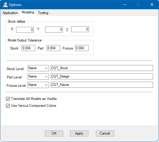
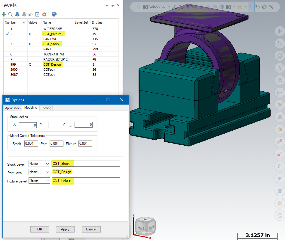
Stock Deltas: Use to position the stock at the correct location on the Vericut machine. Enter the offset values in the X, Y and Z text fields. The values specified will be applied to the stock in addition to any selected Coordinate System.
Model Output Tolerance: Use to specify tolerance values for Stock, Part, and Fixture models.
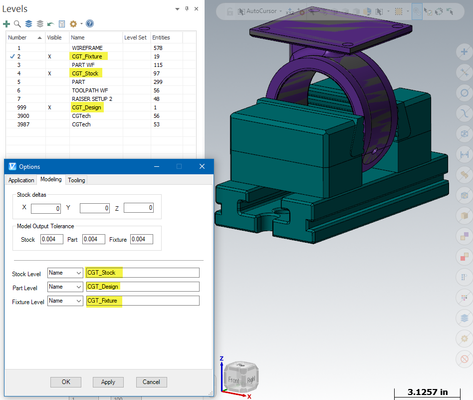
Stock Level Name/Number: Specify the Mastercam level that will be used to export Stock component models.
Part Level Name/Number: Specify the Mastercam level that will be used to export Part component models.
Fixture Level Name/Number: Specify the Mastercam level that will be used to export Fixture component models.
Tooling tab
Specify options for tool output.
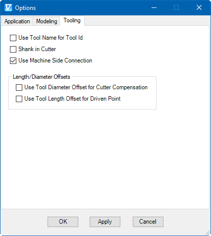
Use Tool Name for Tool Id: select if you want to export the Mastercam Tool Name as the Vericut tool ID. A tool list will not be generated if this option is selected.
Shank in Cutter: select if you wish to have the interface export the Shank as part of the Cutter Component
Use Machine Side Connection: select if you wish to use logic for 3d lathe tool orientation which uses the orientation set in Mastercam > Machine Side Connection.
Length/Diameter Offsets
Use Tool Diameter Offset for Cutter Compensation: Choose this option to have McamV create a Cutter Compensation entry for the tools being exported.
Use Tool Length Offset for Driven Point: Choose this option to have McamV create a Driven Point entry table for the tools being exported.
📝 NOTE:
If any Mastercam Toolpath which is using the tool has the Compensation Type set to Control, then the Interface outputs Tool Manager > Cutter Compensation table for that tool with the value of tool radius (½ of tool diameter).
If any Mastercam Toolpath which is using the tool has the Compensation Type set to Wear or Reverse Wear, then the Interface outputs Tool Manager > Cutter Compensation table for that tool with the value of 0
If no Mastercam Toolpath which is using the tool has this Compensation Type set to Control or Wear or Reverse Wear entry for the tool, then the Interface does not output Tool Manager > Cutter Compensation table for that tool.
Files
Vericut:

Optimizer:

McamV will generate several files to pass Mastercam information to Vericut. All these files will be placed in a single folder.
Working Directory — Enter the \path to the directory where you want the Vericut files output. Use the (Browse) icon to display a directory selection window and use it to specify the \path.
File Name — Enter the "base" name for Vericut files that will be created. By default the name of the Mastercam .MCX file is used.
Project Template — Enter the /path/filename of the "template" .VcProject file that you want loaded in the text field. Use the (Browse) icon to display a file selection window and use it to specify the /path/filename. A "template" .VcProject file is a previously defined Vericut project file. A default Project Template file can be specified using the CGTECH_DEFAULT_PROJECT variable in the batch file that you use to start Mastercam. Example:
set CGTECH_DEFAULT_PROJECT=C:\MCamV_working\McamV_Template.vcproject
Retain Setups: When toggled "on" (checked), MCAMV will append the operations in the Mastercam part file, to the setups that are already defined in your Project Template file, and setups from both files will be contained in the generated project file. Otherwise, and more typically, the imported Mastercam part operations will be the only setups in the generated project file.
Put operations into a single Vericut setup: When toggled “on” (checked), MCAMV will combine all the Mastercam operations into a single Vericut setup.
Mastercam Toolpath Groups
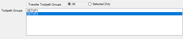
All of the Mastercam ToolPath Groups shown in the Operations Manager are available in this list. Use the list to select the operation that you want selected settings to be applied to.
Transfer Toolpath Groups: Use to specify the toolpath groups to process.
All: Process all toolpath groups in the list.
Selected Only: Process only selected toolpath groups in the list.
When an operation is selected from the list, the Settings for Toolpath Groups field is updated so you can see at a glance which operation you are selecting settings for.

You can create/change setting for all of the Mastercam Toolpath Groups (Operations) shown in the Toolpath Groups List. Use the list to select the toolpath group (operation) that you want selected settings to be applied to. When an operation is selected from the list, the Settings for Toolpath Group field is updated so you can see at a glance which toolpath group (operation) you are selecting settings for.
Models tab
Vericut:
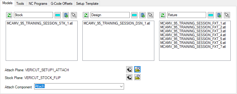
Optimizer:
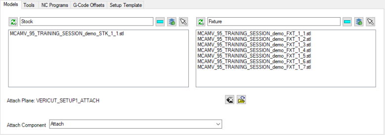
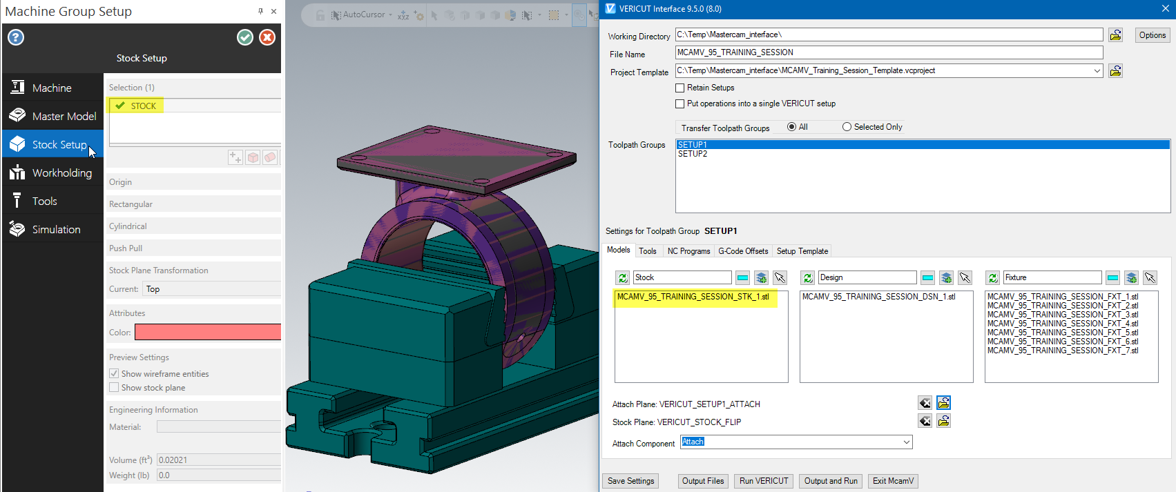
Stock: By default, MCAMV will create STL Stock models based on the information in the Mastercam Machine Group Setup function panel information.
If the Mastercam Machine Group Setup function panel information is not present, then MCAMV will create STL Stock models based on the Mastercam Level > Name/Number set in the Options > Modeling Tab.
Alternately, you can select the geometry to use in the simulation.
Use the  icon to clear the Stock STL File list, and re-read Stock models from the Mastercam Machine Group Setup function panel information
Use the Stock text box on top of the list to specify the Stock component name, which is “Stock” by default.
Use the (Remove) icon to remove the selected STL File(s) from the Stock STL File(s) list.
Use the  (Select Level) to select Stock models from a Mastercam level.
Use the  (Pick) to select Stock model(s) in the Mastercam graphics area. Multiple selection is available.
📝 NOTE: When the Stock models list is empty, MCAMV will create a Stock Block or Cylinder derived from the Mastercam Machine Group Setup function panel information.
Design: By default, MCAMV will create STL Design models based on the information in the Mastercam Machine Group Setup function panel information.
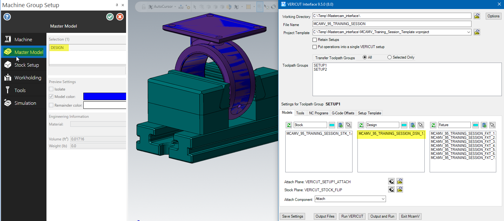
If the Mastercam Machine Group Setup function panel information is not present, then MCAMV will create STL Design models based on the Mastercam Level > Name/Number set in the Options > Modeling Tab.

Alternately, you can select the geometry to use in the simulation.
Use the icon to clear the Design STL File list, and re-read Design models from the Mastercam Machine Group Setup function panel information
Use the Design text box on top of the list to specify the Design component name, which is “Design” by default.
Use the (Remove) icon to remove the selected STL File(s) from the Design STL File(s) list.
Use the (Select Level) to select Design models from a Mastercam level.
Use the (Pick) to select Design model(s) in the Mastercam graphics area. Multiple selection is available.
Fixture: By default, MCAMV will create STL Fixture models based on the information in the Mastercam Machine Group Setup function panel information.
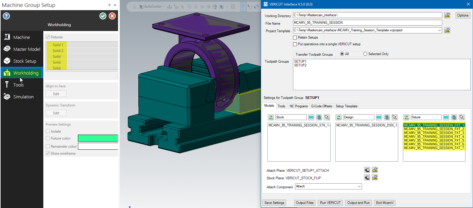
If the Mastercam Machine Group Setup function panel information is not present, then MCAMV will create STL Fixture models based on the Mastercam Level > Name/Number set in the Options > Modeling Tab.
Alternately, you can select the geometry to use in the simulation.
Use the icon to clear the Fixture STL File list, and re-read Fixture models from the Mastercam Machine Group Setup function panel information
Use the Stock text box on top of the list to specify the Fixture component name, which is “Fixture” by default.
Use the (Remove) icon to remove the selected STL File(s) from the Fixture STL File(s) list.
Use the (Select Level) to select Fixture models from a Mastercam level.
Use the (Pick) to select Fixture model(s) in the Mastercam graphics area. Multiple selection is available.
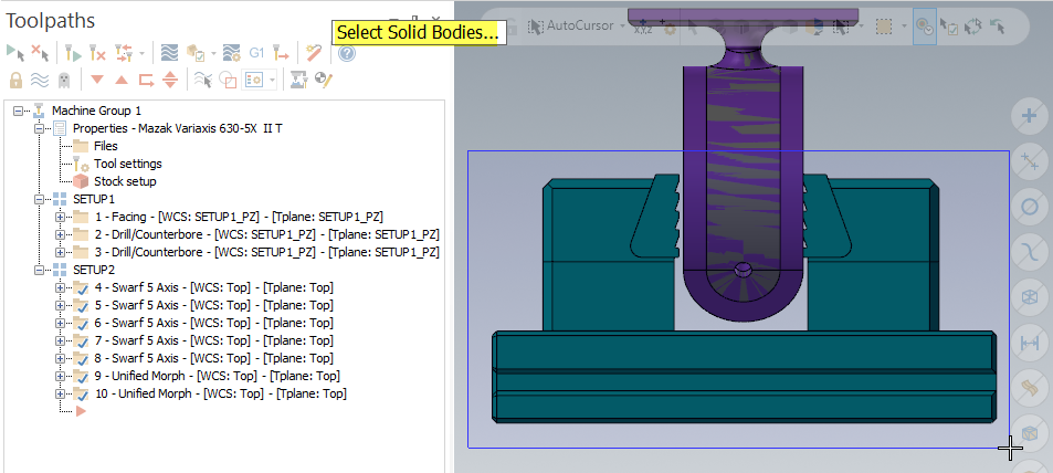
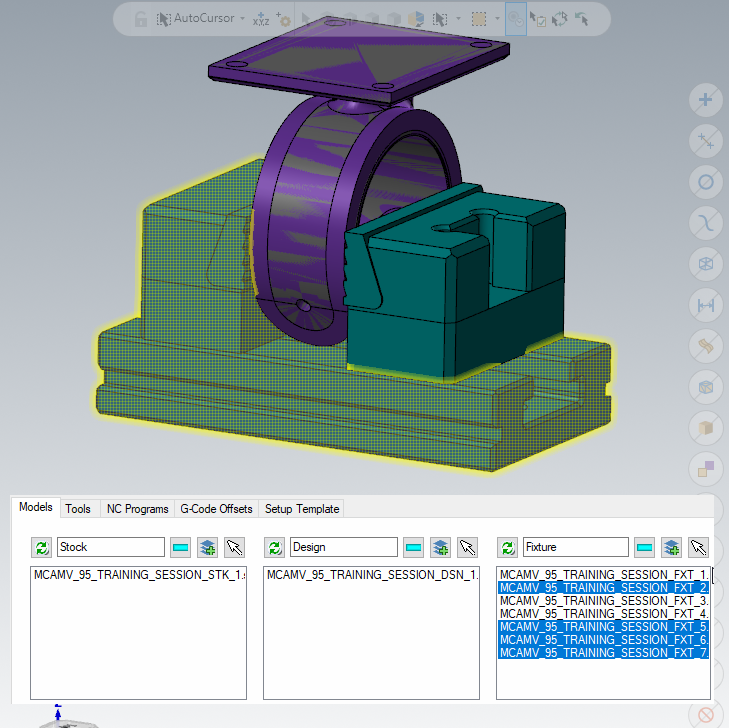
📝 NOTE: When models are selected in the Interface, they are highlited in Mastercam.
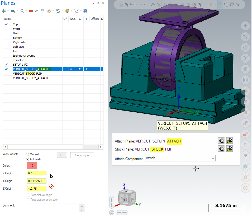
Attach Plane: Use this option to select a Mastercam Plane to represent the Vericut Attach component. The name of the currently selected Plane will be displayed after the Attach Plane label or None will be displayed if there is no currently selected Coordinate System.
Use the  (Clear) icon to clear a previously selected Coordinate System.
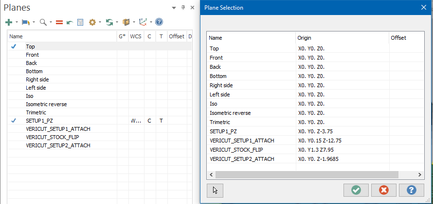
Use the (Browse) icon to display the Mastercam View Selection window and use it to select a Mastercam Plane.
Stock Plane: Use to select a Mastercam Plane that describes how the Cut Stock is to be oriented when transferred from one Vericut setup to the next. The name of the currently selected Coordinate System will be displayed after the Stock Plane label or None will be displayed if there is no currently selected Coordinate System.
Use the (Clear) icon to clear a previously selected Coordinate System.
Use the (Browse) icon to display the Mastercam View Selection window and use it to select a Mastercam Plane.
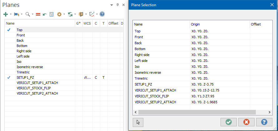
📝 NOTE: By default the Attach Plane and Stock Plane are set if the Plane names include attach and stock.
Tools tab

Select one of the following options from the pull-down list:
Generate Tools from Mastercam: Choose this option to have McamV create a tool library using the tool data in Mastercam.
Use Tools from the Setup Template: Choose this option to use the tool library file stored in the Setup Template instead of one created by McamV.
Merge Tools into Setup Template Tool Library: Choose this option to merge the tool library created by McamV, with the tool library file stored in the Setup Template, and use the "merged" tool library rather than one created by McamV.
Use Selected Tool Library: Choose this option to specify a specific tool library to use. Enter the \path\filename of the tool library file in the text field or use the icon to display a file selection window and use it to specify the /path/filename of the tool library file.
NC Programs tab
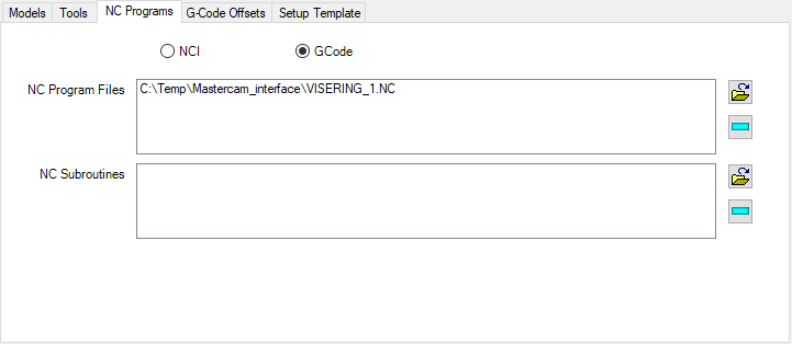
NC Program Type — Use to specify the NC program type. Select either NCI or GCode.
📝 NOTE: To verify NCI data, all you need to do is click the OK button. By default, the files needed by Vericut will be generated in the same folder as the currently accessed Mastercam file.
NC Program Files — Displays a list of NC Program files that will be passed to Vericut.
NC Subroutines — Displays a list of NC Subroutines that will be passed to Vericut.
📝 NOTE: G-code data must be previously generated by Mastercam's post-processor.
(Add) — Use to add tool path files to the NC Program Files / NC Subroutines list.
 (Remove) — Use to remove the highlighted file(s) from the NC Program Files / NC Subroutines list.
📝 NOTE: G-code data must be previously generated by Mastercam's post-processor.
GCode Tables tab
GCode Tables tab enables you to define Vericut GCode tables
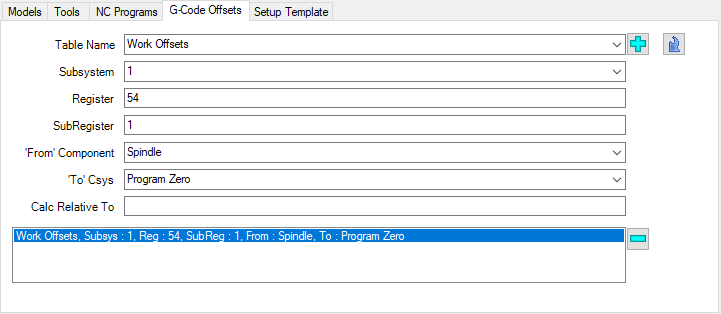
Table Name — Select the desired table name from the Table List pull-down list.
The Table List pull-down list contains the following Vericut G-Code tables: Program Zero, Work Offsets, and Base Work Offset.
The Program Zero table is used to specify the programmed zero location of a G-Code NC program file taking Tool Length Compensation into consideration.
The Work Offsets table is used to store the work coordinate system offset (fixture offset) values.
The Base Work Offset table is used to specify the location from which work offsets are based.
Subsystem — Use to specify the machine subsystem ID for which the table is being defined. Select the subsystem ID from the pull-down list.
Register — Specify the table register number. Example: for a G54 enter 54.
SubRegister — Specify the table sub-register number. Example: for a G54 enter 54.
From Component — From the pull-down list select the name of the component that represents the "from" point for determining the program zero offset.
To Csys — From the pull-down list select the name of a CSYS to represent the "to" point for determining the program zero offset. When "Program_Zero" is selected, MCAMV will use the WCS specified in the Toolpath Group.
Calc Relative to — This feature enables you to have a relational offset recalculated in the machine position where the offset will be used. The new position is immediately calculated and stored and therefore is not dependent on the machine position when the offset is activated.
Use the  (Add) icon to add a table. Make the appropriate selections and press the “Add”.
Use the  (Modify) icon to modify an existing table. Select the table in the current list, make the appropriate changes and press the “Modify”.
Use the (Remove) icon to remove a table. Select it in the list and press the “Remove”.
📝 NOTE: If no table is specified the GCode tables in the VMC will be used:

Setup Template tab

Setup Template: Enter the /path/filename of the Setup "template" file that you want loaded in the text field. Use the (Clear) icon to set the Setup Template text field equal to the Project Template text field. When the text field is blank, MCAMV will use the Project Template file specified above.
Use the (Browse) icon to display a file selection window and use it to specify the /path/filename. A setup "template" is a previously defined Vericut VcProject file that containing files and settings required for Vericut simulation.
Use Views from the Setup Template: When toggled "on" (checked), Vericut will use the views stored in the Setup Template rather than the views created by MCAMV. If unchecked Vericut will launch with only 1 Workpiece view and will be orientated the same as the current view in Mastercam.
Save and Output Files
Vericut:

Optimizer:

Save Settings: Saves McamV data as note entities, these entries are known as Custom Data.
Output Files: Outputs all files, for all operations, including the selected models, tool library files, updated project and setup files, and the "operations" file that assembles all of this information into a Vericut "project" file.
Run Vericut: Launches Vericut using the files created by Output Files.
Output and Run: Use Output and Run to output the files needed by Vericut and then launch Vericut in the same step.
Exit McamV: Closes the MCAMV window. Note: To save McamV settings in the Mastercam part file you have to press the Save Settings button. However the ‘prefs’ file is modified on Exit.
Usage Variables
The following optional environment variables are available for use with the Mastercam Interface.
| No. | Environment Variable | Example |
|---|---|---|
| 1 | CGTECH_MCAM_NOTE_LOG | C:\Temp\notes_dump.txt |
| 2 | VCHOOK_DEBUG | 1 |
| 3 | CGTECH_MCAMV_NEW_TLS | 1 |
| 4 | CGTECH_MCAM_NEUTRAL_TOOL_OPTION | 1 |
CGTECH_MCAM_NOTE_LOG set if the user wishes to output the notes to a text file.
VCHOOK_DEBUG If variable VCHOOK_DEBUG is set to 3, The Mastercam Interface writes a transaction log file to the Mastercam Interface > Output Directory.
Ref: C:\Temp\Mastercam_interface\output*VcHookDebug.txt*
CGTECH_MCAMV_NEW_TLS
Mastercam v9.5.1 supports the new tooling API logic (which exports Vericut/Optimizer 9.4 version file). To activate the new tooling API logic, set the following environment variable… set CGTECH_MCAMV_NEW_TLS=1. If the above environment variable is not set, then the old tls logic is used.
📝 NOTE: Currently for Corp Support testing
CGTECH_MCAM_NEUTRAL_TOOL_OPTION
With this variable set, the Interface > Options > Tool tab will display the Output Neutral Orientation option which will output tools with no extra rotations, the only rotation will be the Mastercam XY to Vericut ZX. This logic is used when exporting Mastercam 3D Turning tools
Preferences
Preferences File
Also known as ‘prefs’ file, stores all user specified ‘global’ settings for interface operation. The settings stored are called ‘global’ because they are responsible for overall look & feel and operational behavior of the interface. They are not tied to any specific Mastercam project. By default, ‘Preferences’ file is generated at C:\Users\username\mcamv_version number_user.prefs.
The data in the dialog fields is saved in the Mastercam part file as blanked notes on a specified level so that when you save the part and later load it again, the values in the McamV dialog will be restored. By default, this level is 3987 but you can change it in the Options. You can also choose to ignore this saved data, which is an Options checkbox.
To output the notes to a text file use the environment variable CGTECH_MCAM_NOTE_LOG to set the notes file name (e.g. C:\Temp\notes_dump.txt).
Transaction Log file If variable VCHOOK_DEBUG is set to 3, The Mastercam Interface writes a transaction log file to the Mastercam Interface > Output Directory.
Ref: C:\Temp\Mastercam_interface\output\VcHookDebug.txt
"Quick Start" training session
The Mastercam-to-Vericut Interface “Quick Start” training session is designed to quickly teach a Vericut user the “basics” of using the Mastercam Interface. The download includes: CAD/CAM files, Vericut files, and step-by-step training sessions in PDF format.
These training sessions are included supplied with 2 different downloads:
- Mastercam_interface.zip
- Mastercam_interface_optimizer.zip
Download: https://vericut.com/products/vericut-interfaces
📝 NOTE: to run the Quick Start files, Mastercam X6 or later is required.