Tool Change By List panel
Opened by clicking on the Tool Change By List button in the Configure Tooling menu. The upper half of the Project tab icon opens the list directly while the lower half gives you the option of opening specific tabs on the panel. The features on this window enable you to maintain a list of references that link tool change events to tools stored in the current Tool Library file. You can use this list to specify tools to use with sequential tool changes, or to replace tools specified for use in the NC program file.
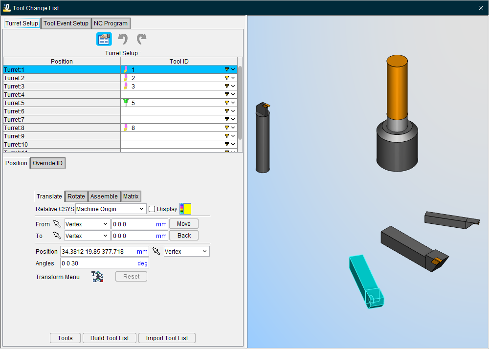
The Tool Change List panel is one of the dockable panels enabling you to dock it inside the main window if you choose.
 (Configure) — When this feature is active, the Position and Override ID tabs will be displayed at the bottom of the panel.
 (Undo) — Use this icon to “undo” changes made in the Tool Change List panel. The icon will be grayed out until a change is made in the Tool Change List panel. Once a change is made in the Tool Change List panel the icon will display as shown here. Click on the icon to “undo” the last change made to the Tool Change List panel. Click on the icon again to “undo” the next to the last change and so on. There is no limit to the number of changes that you can “undo”.
 (Redo) — Use this icon to “redo” changes that you have used the Undo feature on. The icon will be grayed out until the Undo feature is used. Once the Undo feature is used, the icon will display as shown here. Click on the icon to “redo” the last “undo”. Click on the icon again to “undo” the next to the last “undo” and so on. There is no limit to the number of “undo” actions that you can “redo”.
Table — The table of each Tool Change List tab contains specific information relative to that tab that can be altered to manage tool changes, turret setups, tool chain setups, and so on. See Turret Setup, Tool Event Setup, or NC Program tab sections to learn more about each tab's table.
Tools — This button opens the Tool Manager.
Build Tool List — Builds a tool list by scanning the files in the NC Program list and looking for the tool change events specified by the List Tool Change By feature (see above). When multiple NC program files are listed, a comprehensive tool change events list is created with all tool change activity from all listed NC programs. Sample output is shown in the following image. If there is a tool chain, build tool list action will remove current tools on the chain and sequentially add tool from the NC program to the chain pockets.
If a Tool ID in the Tool Change List does not exist in the current tool library file, the Tool ID will appear in red text and at the very top of the Tool ID’s pull-down list. This condition can result if the tool library file is changed or if the specific tool has been deleted from tool library file.
Import Tool List — Similar to the Build Tool List button but with the change that the list that is built here is imported from an existing .csv file that can be selected through the Open Spread Sheet File window.
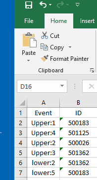
The format for the .csv or Excel file is to have the Event in the first column and the ID in the second column as shown below. In the case of multiple sub system/channel inputs, the format "subsystem name + colon + event number" can be used in the event column as seen below:
Turret Setup
The features in the Turret Setup tab enable you to load or change tools, or change tool positions in a turret.
Each record in the Turret Setup Table represents a position on a turret. The table presents information for the Turret Position and for the Tool ID associated with that position. By selecting the Tool ID cell, you can assign a tool to the desired position.
When you select a record in the Turret Setup Table, the record becomes highlighted. The Tool Display area in Tool Manager updates to display the turret with all tools currently loaded in it. The tool represented by the selected record is marked in the turret display as well as becomes highlighted in the Tool Manager Tool Table.
To add or change a tool associated with the highlighted turret record, click in the Tool ID field for that record and select the desired tool from the pull-down list. The list will contain all tools in the current Tool Library and a blank field or select Tool ID in Tool Manager, drag and drop in the table at the desired location.
The Turret Setup, Position tab is used to correctly orient a tool (or tool assembly) on a turret, similar to orienting models. The features on the tab work the same as the features on the corresponding tab on the Tool Manager Assembly tab.
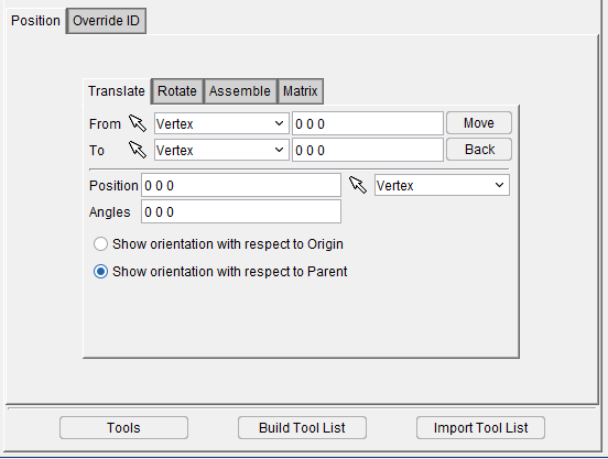
Translate tab — Features on this tab are used to translate the selected tool via indicating "from" and "to" points to move the tool.
Rotate tab — Features on this tab are used to rotate the selected tool about a rotation center point.
Assemble tab — The features on this tab enable you to assemble tools on a turret, by mating, or aligning, one to three planar surfaces with surfaces on the turret, similar to assembling tool assemblies or models.
Matrix tab — Features on this tab move the selected tool via a twelve parameter transformation matrix.
Position — Specifies the absolute XYZ position of the tool component relative to the tool origin. Values in this field are separated by spaces. You can use the mouse icon and the pull down menu from which you can designate which feature to analyze in order to select a position from the Graphics Display Area by clicking on the desired location.
Angles — Specifies the absolute XYZ rotation of the tool component relative to the tool origin. Values in this field are separated by spaces.
Show orientation with respect to — Toggle between showing orientation relative to the origin of the piece or relative to the parent piece.
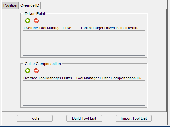
Override ID tab
The features on the Override ID tab are used to alter Driven Point and Cutter Compensation values. Use the green plus icon ( ) to add an override to affect previously inserted Driven Point or Cutter Compensation values. Use the red removal icon (
 ) to delete the override. Enter desired numerical value for Driven Point or Cutter Compensation ID and select from the pull down menu desired value from Tool Manager definition or enter desired numerical value for Driven Point or Cutter Compensation ID manually.
Tool Event Setup
The features in the Tool Event Setup tabenable you to load or change tool events.
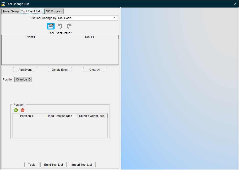
List of tool change events expected to occur during the simulation as indicated by the active List Tool Change By option and IDs of the tools to use for each. Event text must match the tool change record text exactly as it appears in the NC program file. Type or left-click and choose the tool ID from an option list. Right-click to add and delete tool list entries.
The Tool Change List consists of the following columns of information.
List Tool Change By — Use this pulldown feature to select the order in which tools will be displayed. Sort by Cutter Desc., Vericut TC, Tool Code, Prog. Stop, and Tool Code Per File options.
Event ID — Displays the tool change event.
Tool ID — Displays the ID of the tool associated with the tool change event or select Tool ID in Tool Manager, drag and drop in the table at the desire location.
Add Event — This feature enables you to add a new tool change Event/Tool ID to the Tool Change List. Select the Tool ID from the Tool ID pull-down list.
Delete Event — This feature enables you to delete the highlighted Event/Tool ID from the Tool Change List.
Clear All — Clears all Event/Tool ID records from the from the Tool Change List.
📝 NOTE: Always reset (press  (Reset Model) on the main window) after making changes.
Position tab — Enables you to control the positioning of the tool. Use the green plus icon () to add a new positional entry. Use the red removal icon () to delete the entry. You can manually edit the Position ID, Head Rotation, and Spindle Orient values by clicking on their respective cells and typing in the desired value. Position can also be set via Offsets: Location when Machine Locations is selected and the Location Name is set to Head Position.
Override ID tab — Enables you alter Driven Point and Cutter Compensation values.
Skip Duplicate Cutter Descriptions — When toggled on (checked), causes Optimizer to skip duplicate cutter descriptions when building the tool change event list. This feature is useful for suppressing redundant tool changes often output by CAM systems for different cutting operations by the same cutter.
NC Program
The features in the NC Program tabenable you to assign Tool IDs to already loaded NC Programs.
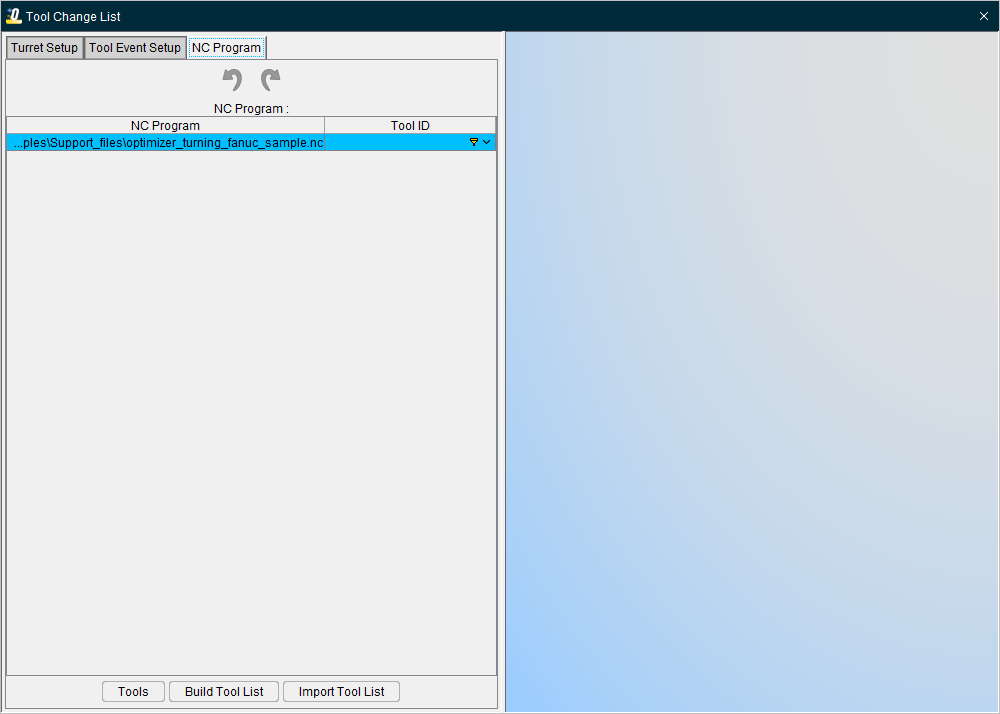
Changing Tools by NC Program File Names
Use the procedure below to have Optimizer change tools based on NC program file names.
📝 NOTE: This option requires using a Tool Library.
To change tools with tool path file names:
- If needed, click on the
 (Project Tree) icon in the Toolbar, or click Project tab > Project Tree in the menu ribbon to display the Project Tree.
 - In the Project Tree, specify the NC program files to be simulated in the setup.
- In the Project Tree Configure Tooling menu, choose the File Name option from the Tool Change By pull-down list.
-
Click on the Tool Change By File button to open the Tool Change by File Name panel. The Tool Change by File Name panel will display with a record for each NC program listed for the setup.
-
In the Tool Change by File Name panel, click on the first NC program in the list so that it becomes highlighted.
- Click in the Tool ID column and then select the tool ID of the tool that is to be used for cutting the highlighted NC program.
- Repeat Step 6 for every NC program in the list.
- Click on the
 in the Tool Change List tab to close the Tool Change by File Name panel.